

September 1995
1/124
This is advanced information from SGS-THOMSO N. Details are subject to change without notice.
ST10 FAMILY
PROGRAMMING MANUAL
The SGS-THOMSON family of 16-bit microcontrollers offers devices that provide various levels of periph-
eral performance and programmability. This allows each specific application to be equiped with the mi-
crocontroller that fits best to the required functionality and performance.
The SGS-THOMSON family concept provides an easy path to upgrade existing applications or to climb
the next level of performance in order to realize a subsequent more sophisticated design. Two major
characteristics enable this upgrade path to save and reuse almost all of the engineering efforts that have
been made for previous designs:
- All family members are based on the same basic architecture
- All family members execute the same instructions (except for upgrades for new members)
The fact that all members execute the same instructions (almost) saves knowhow with respect to the un-
derstanding of the controller itself and also with respect to the used tools (assembler, disassembler, com-
piler, etc.).
This instruction set manual provides an easy and direct access to the instructions of the SGS-THOMSON
16-bit microcontrollers by listing them according to different criteria, and also unloads the technical man-
uals for the different devices from redundant information.
This manual also describes the different addressing mechanisms and the relation between the logical ad-
dresses used in a program and the resulting physical addresses.
There is also information provided to calculate the execution time for specific instructions depending on
the used address locations and also specific exceptions to the standard rules.
Description Levels
In the following sections the instructions are compiled according to different criteria in order to provide dif-
ferent levels of precision:
Cross Reference Tables summarize all instructions in condensed tables
The Instruction Set Summary groups the individual instructions into functional groups
The Opcode Table references the instructions by their hexadecimal opcode
The Instruction Description describes each instruction in full detail
All instructions listed in this manual are executed by the following devices:
ST10R165, ST10F167 and derivatives.
A few instructions (ATOMIC and EXTended instructions) have been added for these devices and are not
recognized by the following devices:
ST10F166, ST10R166, ST10166, ST10F160.
These differences are noted for each instruction, where applicable.

Table of Contents
2/124
1 INTRODUCTION AND OVERVIEW . . . . . . .3
1.1 Addressing Modes . . . . . . . . . . . . . . . . . . .3
1.2 Instruction State Times . . . . . . . . . . . . . .10
2 INSTRUCTION SET SUMMARY . . . . . . . .15
2.1Short Instruction Summary . . . . . . . . . . . . 15
2.2 Instruction Set Summary . . . . . . . . . . . . . 18
2.3 Instru2ction Opcodes . . . . . . . . . . . . . . . .29
3 INSTRUCTION SET . . . . . . . . . . . . . . . . . . 35
Instruction Description . . . . . . . . . . . . . . . . . .35
ADD . . . . . . . . . . . . . . . . . . . . . . . . . . . . . . . 41
ADDB . . . . . . . . . . . . . . . . . . . . . . . . . . . . . . . 42
ADDC . . . . . . . . . . . . . . . . . . . . . . . . . . . . . . .43
ADDBC . . . . . . . . . . . . . . . . . . . . . . . . . . . . . 44
AND . . . . . . . . . . . . . . . . . . . . . . . . . . . . . . . 45
ANDB . . . . . . . . . . . . . . . . . . . . . . . . . . . . . . 46
ASHR . . . . . . . . . . . . . . . . . . . . . . . . . . . . . . 47
ATOMIC . . . . . . . . . . . . . . . . . . . . . . . . . . . . 48
BAND . . . . . . . . . . . . . . . . . . . . . . . . . . . . . . 49
BCLR . . . . . . . . . . . . . . . . . . . . . . . . . . . . . . . 50
BCMP . . . . . . . . . . . . . . . . . . . . . . . . . . . . . . . 51
BFLDH . . . . . . . . . . . . . . . . . . . . . . . . . . . . . . 52
BFLDL. . . . . . . . . . . . . . . . . . . . . . . . . . . . . . . 53
BMOV . . . . . . . . . . . . . . . . . . . . . . . . . . . . . . 54
BMOVN. . . . . . . . . . . . . . . . . . . . . . . . . . . . . 55
BOR . . . . . . . . . . . . . . . . . . . . . . . . . . . . . . . . 56
BSET . . . . . . . . . . . . . . . . . . . . . . . . . . . . . . . 57
BXOR . . . . . . . . . . . . . . . . . . . . . . . . . . . . . . .58
CALLA . . . . . . . . . . . . . . . . . . . . . . . . . . . . . . 59
CALLI . . . . . . . . . . . . . . . . . . . . . . . . . . . . . . . 60
CALLR . . . . . . . . . . . . . . . . . . . . . . . . . . . . . . 61
CALLS . . . . . . . . . . . . . . . . . . . . . . . . . . . . . . 62
CMP . . . . . . . . . . . . . . . . . . . . . . . . . . . . . . . 63
CMPB . . . . . . . . . . . . . . . . . . . . . . . . . . . . . . . 64
CMPD1 . . . . . . . . . . . . . . . . . . . . . . . . . . . . . 65
CMPD2 . . . . . . . . . . . . . . . . . . . . . . . . . . . . . 66
CMPI1. . . . . . . . . . . . . . . . . . . . . . . . . . . . . . . 67
CMPI2. . . . . . . . . . . . . . . . . . . . . . . . . . . . . . 68
CPL. . . . . . . . . . . . . . . . . . . . . . . . . . . . . . . . .69
CPLB . . . . . . . . . . . . . . . . . . . . . . . . . . . . . . . 70
DISWDT . . . . . . . . . . . . . . . . . . . . . . . . . . . . 71
DIV . . . . . . . . . . . . . . . . . . . . . . . . . . . . . . . . .72
DIVL . . . . . . . . . . . . . . . . . . . . . . . . . . . . . . . .73
DIVLU . . . . . . . . . . . . . . . . . . . . . . . . . . . . . . 74
DIVU . . . . . . . . . . . . . . . . . . . . . . . . . . . . . . . .75
EINIT. . . . . . . . . . . . . . . . . . . . . . . . . . . . . . . . 76
EXTR . . . . . . . . . . . . . . . . . . . . . . . . . . . . . . 77
EXTP . . . . . . . . . . . . . . . . . . . . . . . . . . . . . . . 78
EXTPR . . . . . . . . . . . . . . . . . . . . . . . . . . . . . . 79
EXTS . . . . . . . . . . . . . . . . . . . . . . . . . . . . . . 80
EXTSR . . . . . . . . . . . . . . . . . . . . . . . . . . . . . 81
IDLE . . . . . . . . . . . . . . . . . . . . . . . . . . . . . . . . 82
JB . . . . . . . . . . . . . . . . . . . . . . . . . . . . . . . . . . 83
JBC. . . . . . . . . . . . . . . . . . . . . . . . . . . . . . . . . 84
JMPA . . . . . . . . . . . . . . . . . . . . . . . . . . . . . . . 85
JMPI . . . . . . . . . . . . . . . . . . . . . . . . . . . . . . . . 86
JMPR . . . . . . . . . . . . . . . . . . . . . . . . . . . . . . . 87
JMPS . . . . . . . . . . . . . . . . . . . . . . . . . . . . . . . 88
JNB. . . . . . . . . . . . . . . . . . . . . . . . . . . . . . . . . 89
JNBS . . . . . . . . . . . . . . . . . . . . . . . . . . . . . . 90
MOV . . . . . . . . . . . . . . . . . . . . . . . . . . . . . . . . 91
MOVB . . . . . . . . . . . . . . . . . . . . . . . . . . . . . . 92
MOVBS. . . . . . . . . . . . . . . . . . . . . . . . . . . . . 93
MOVBZ. . . . . . . . . . . . . . . . . . . . . . . . . . . . . 94
MUL . . . . . . . . . . . . . . . . . . . . . . . . . . . . . . . . 95
MULU . . . . . . . . . . . . . . . . . . . . . . . . . . . . . . 96
NEG . . . . . . . . . . . . . . . . . . . . . . . . . . . . . . . . 97
NEGB . . . . . . . . . . . . . . . . . . . . . . . . . . . . . . . 98
NOP . . . . . . . . . . . . . . . . . . . . . . . . . . . . . . . . 99
OR . . . . . . . . . . . . . . . . . . . . . . . . . . . . . . . . 100
ORB . . . . . . . . . . . . . . . . . . . . . . . . . . . . . . 101
PCALL . . . . . . . . . . . . . . . . . . . . . . . . . . . . . 102
POP . . . . . . . . . . . . . . . . . . . . . . . . . . . . . . . 103
PRIOR . . . . . . . . . . . . . . . . . . . . . . . . . . . . 104
PUSH . . . . . . . . . . . . . . . . . . . . . . . . . . . . . 105
PWRDN . . . . . . . . . . . . . . . . . . . . . . . . . . . . 106
RET . . . . . . . . . . . . . . . . . . . . . . . . . . . . . . . 107
RETI . . . . . . . . . . . . . . . . . . . . . . . . . . . . . . . 108
RETP . . . . . . . . . . . . . . . . . . . . . . . . . . . . . . 109
RETS . . . . . . . . . . . . . . . . . . . . . . . . . . . . . 110
ROL . . . . . . . . . . . . . . . . . . . . . . . . . . . . . . 111
ROR . . . . . . . . . . . . . . . . . . . . . . . . . . . . . . 112
SCXT . . . . . . . . . . . . . . . . . . . . . . . . . . . . . . 113
SHL. . . . . . . . . . . . . . . . . . . . . . . . . . . . . . . . 114
SHR . . . . . . . . . . . . . . . . . . . . . . . . . . . . . . . 115
SRST . . . . . . . . . . . . . . . . . . . . . . . . . . . . . . 116
SRVWDT . . . . . . . . . . . . . . . . . . . . . . . . . . 117
SUB . . . . . . . . . . . . . . . . . . . . . . . . . . . . . . 118
SUBB . . . . . . . . . . . . . . . . . . . . . . . . . . . . . . 119
SUBC . . . . . . . . . . . . . . . . . . . . . . . . . . . . . . 120
SUBCB . . . . . . . . . . . . . . . . . . . . . . . . . . . . . 121
TRAP . . . . . . . . . . . . . . . . . . . . . . . . . . . . . 122
XOR . . . . . . . . . . . . . . . . . . . . . . . . . . . . . . . 123
XORB . . . . . . . . . . . . . . . . . . . . . . . . . . . . . . 124
ST10 Programming Manual
3/124
1 INTRODUCTION AND OVERVIEW
1.1 Addressing Modes
The SGS-THOMSON 16-bit microcontrollers provide a large number of powerful addressing modes for
access to word, byte and bit data (short, long, indirect), or to specify the target address of a branch in-
struction (absolute, relative, indirect). The different addressing modes use different formats and cover dif-
ferent scopes.
Short Addressing Modes
All of these addressing modes use an implicit base offset address to specify an 18-bit or 24-bit physical
address (ST10X166 devices use a 18-bit physical address).
Short addressing modes allow to access the GPR, SFR or bit-addressable memory space:
Physical Address = Base Address +
∆
*
Short Address
Note:
∆
is 1 for byte GPRs,
∆
is 2 for word GPRs.
*)
The Extended Special Function Register (ESFR) area is not available in the ST10X166 devices.
Mnemonic
Physical Address
Short Address Range
Scope of Access
Rw
(CP)
+ 2*Rw
Rw
= 0...15
GPRs
(Word)
Rb
(CP)
+ 1*Rb
Rb
= 0...15
GPRs
(Byte)
reg
00’FE00
h
+ 2*reg
00’F000
h
+ 2*reg
*)
(CP)
+ 2*(reg
∧
0F
h
)
(CP)
+ 1*(reg
∧
0F
h
)
reg
= 00
h
...EF
h
reg
= 00
h
...EF
h
reg
= F0
h
...F F
h
reg
= F0
h
...F F
h
SFRs
(Word, Low byte)
ESFRs
(Word, Low byte)
*)
GPRs
(Word)
GPRs
(Bytes)
bitoff
00’FD00
h
+ 2*bitoff
00’FF00
h
+ 2*(bitoff
∧
FF
h
)
(CP)
+ 2*(bitoff
∧
0F
h
)
bitoff
= 00
h
...7F
h
bitoff
= 80
h
...EF
h
bitoff
= F0
h
...F F
h
RAM
Bit word offset
SFR
Bit word offset
GPR
Bit word offset
bitaddr
Word offset as with bitoff.
Immediate bit position.
bitoff
= 00
h
...FF
h
bitpos
= 0...15
Any single bit

ST10 Programming Manual
4/124
Rw, Rb:
Specifies direct access to any GPR in the currently active context (register bank). Both ’Rw’
and ’Rb’ require four bits in the instruction format. The base address of the current register
bank is determined by the content of register CP. ’Rw’ specifies a 4-bit word GPR address rel-
ative to the base address (CP), while ’Rb’ specifies a 4 bit byte GPR address relative to the
base address (CP).
reg:
Specifies direct access to any (E)SFR or GPR in the currently active context (register bank).
’reg’ requires eight bits in the instruction format. Short ’reg’ addresses from 00h to EFh always
specify (E)SFRs. In that case, the factor ’
∆
’ equates 2 and the base address is 00’FE00h for
the standard SFR area or 00’FE00h for the extended ESFR area. ‘reg’ accesses to the ESFR
area require a preceding EXT*R instruction to switch the base address (not available in the
ST10X166 devices). Depending on the opcode of an instruction, either the total word (for
word operations) or the low byte (for byte operations) of an SFR can be addressed via ’reg’.
Note that the high byte of an SFR cannot be accessed via the ’reg’ addressing mode. Short
’reg’ addresses from F0h to FFh always specify GPRs. In that case, only the lower four bits of
’reg’ are significant for physical address generation, and thus it can be regarded as being
identical to the address generation described for the ’Rb’ and ’Rw’ addressing modes.
bitoff:
Specifies direct access to any word in the bit-addressable memory space. ’bitoff’ requires
eight bits in the instruction format. Depending on the specified ’bitoff’ range, different base
addresses are used to generate physical addresses: Short ’bitoff’ addresses from 00h to 7Fh
use 00’FD00h as a base address, and thus they specify the 128 highest internal RAM word
locations (00’FD00h to 00’FDFEh). Short ’bitoff’ addresses from 80h to EFh use 00’FF00h as
a base address to specify the highest internal SFR word locations (00’FF00h to 00’FFDEh) or
use 00’F100h as a base address to specify the highest internal ESFR word locations
(00’F100h to 00’F1DEh). ‘bitoff’ accesses to the ESFR area require a preceding EXT*R
instruction to switch the base address (not available in the ST10X166 devices). For short
’bitoff’ addresses from F0h to FFh, only the lowest four bits and the contents of the CP
register are used to generate the physical address of the selected word GPR.
bitaddr:
Any bit address is specified by a word address within the bit-addressable memory space (see
’bitoff’), and by a bit position (’bitpos’) within that word. Thus, ’bitaddr’ requires twelve bits in
the instruction format.
Addressing Modes (Cont’d)
ST10 Programming Manual
5/124
Long Addressing Mode
This addressing mode uses one of the four DPP registers to specify a physical 18-bit or 24-bit address.
Any word or byte data within the entire address space can be accessed with this mode.
The second generation of ST10 devices, such as the ST10R165 or the ST10F167 also support an over-
ride mechanism for the DPP adressing scheme.
Note: Word accesses on odd byte addresses are not executed, but rather trigger a hardware trap.
After reset, the DPP registers are initialized in a way that all long addresses are directly mapped
onto the identical physical addresses, within segment 0.
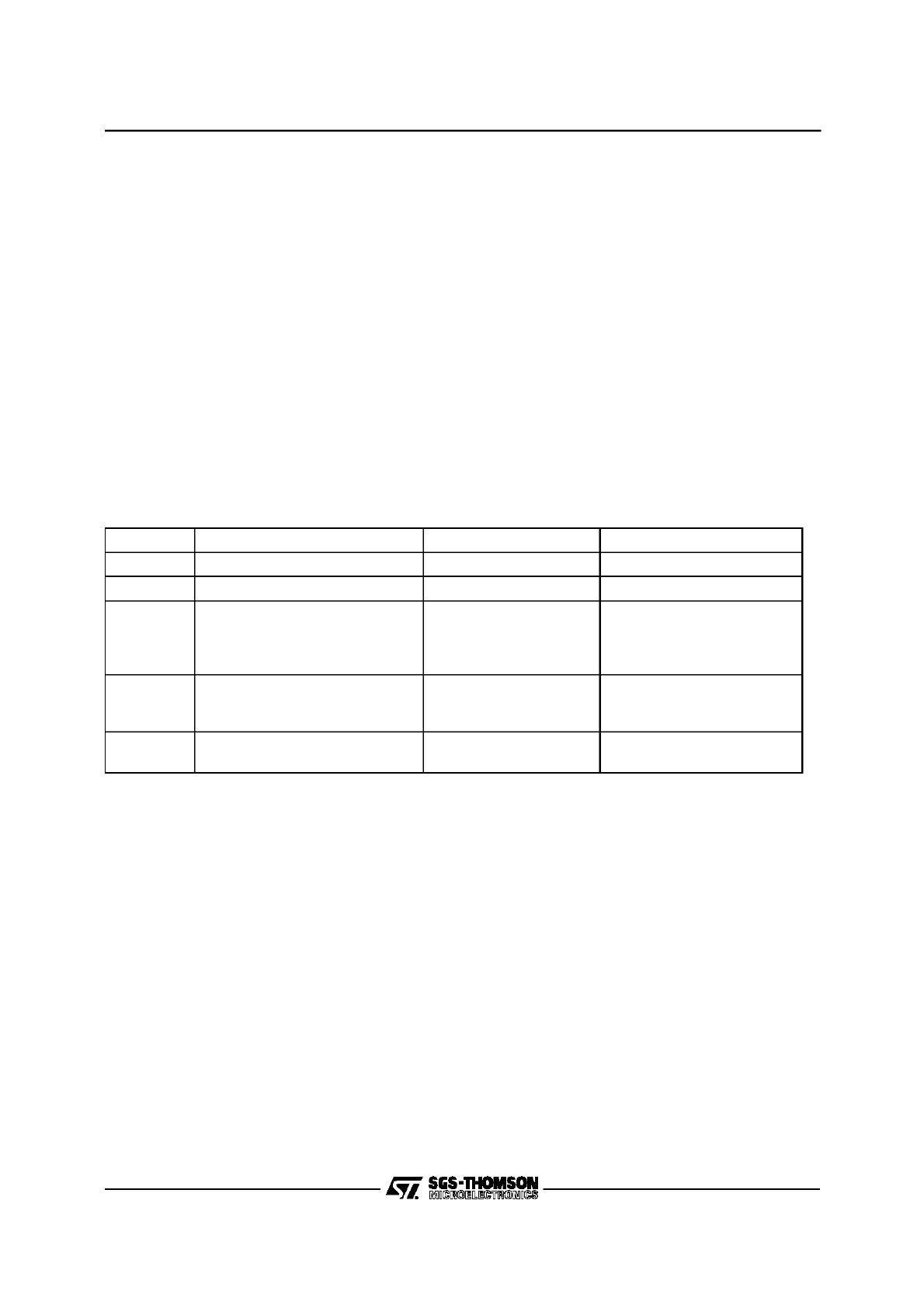
Any long 16-bit address consists of two portions, which are interpreted in different ways. Bits 13...0 spec-
ify a 14-bit data page offset, while bits 15...14 specify the Data Page Pointer (1 of 4), which is to be used
to generate the physical 18-bit or 24-bit address (see figure below).
Figure 1. Interpretation of a 16-bit Long Address
The ST10X166 devices support an address space of up to 256 KByte, while the second generation of
ST10 devices support an address space of up to 16 MByte, so only the lower four or ten bits (respectively)
of the selected DPP register content are concatenated with the 14-bit data page offset to build the phys-
ical address.
The long addressing mode is referred to by the mnemonic ‘mem’.
Mnemonic
Physical Address
Long Address Range
Scope of Access
mem
(DPP0) || mem
∧
3FFF
h
(DPP1) || mem
∧
3FFF
h
(DPP2) || mem
∧
3FFF
h
(DPP3) || mem
∧
3FFF
h
0000
h
...3FF F
h
4000
h
...7FF F
h
8000
h
...BFF F
h
C000
h
...FFF F
h
Any Word or Byte
mem
pag
|| mem
∧
3FFF
h
0000
h
...FFF F
h
(14-bit)
Any Word or Byte
mem
seg
|| mem
0000
h
...FFF F
h
(16-bit)
Any Word or Byte
0
15
14 13
16-bit Long Address
DPP0
DPP1
DPP2
DPP3
14-bit page offset
18/24-bit Physical Address
Addressing Modes (Cont’d)
ST10 Programming Manual
6/124
DPP Override Mechanism in the second generation of ST10 devices
Other than the older devices from the ST10X166 group the second generation of ST10 devices such as
the ST10R165 or the ST10F167 provide an override mechanism that allows to bypass the DPP address-
ing scheme temporarily.
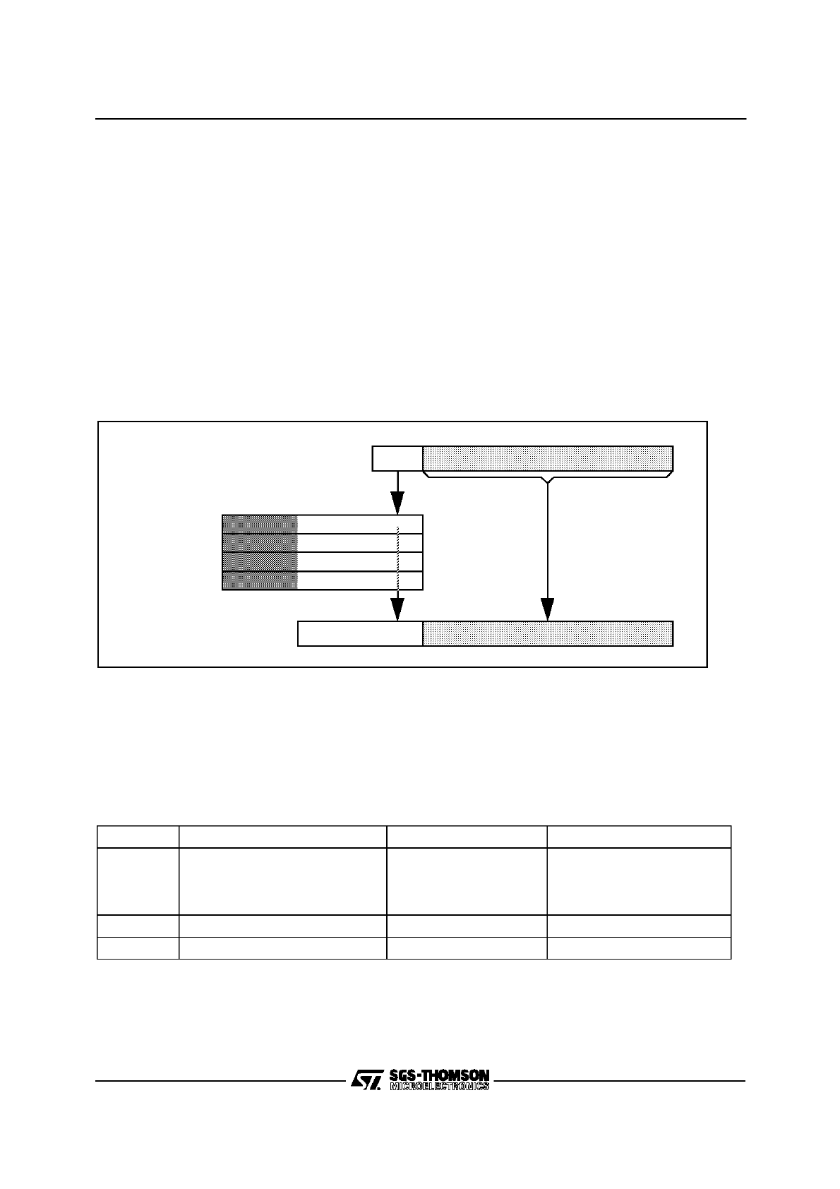
The EXTP(R) and EXTS(R) instructions override this addressing mechanism. Instruction EXTP(R) re-
places the content of the respective DPP register, while instruction EXTS(R) concatenates the complete
16-bit long address with the specified segment base address. The overriding page or segment may be
specified directly as a constant (#pag, #seg) or via a word GPR (Rw).
Figure 2. Overriding the DPP Mechanism
.
Indirect Addressing Modes
These addressing modes can be regarded as a combination of short and long addressing modes. This
means that long 16-bit addresses are specified indirectly by the contents of a word GPR, which is speci-
fied directly by a short 4-bit address (’Rw’=0 to 15). There are indirect addressing modes, which add a
constant value to the GPR contents before the long 16-bit address is calculated. Other indirect address-
ing modes allow decrementing or incrementing the indirect address pointers (GPR content) by 2 or 1 (re-
ferring to words or bytes).
In each case, one of the four DPP registers is used to specify physical 18-bit or 24-bit addresses. Any word
or byte data within the entire memory space can be addressed indirectly.
Note: The exceptions for instructions EXTP(R) and EXTS(R), ie. overriding the DPP mechanism, apply
in the same way as described for the long addressing modes.
0
15
14 13
16-bit Long Address
#pag
14-bit page offset
24-bit Physical Address
0
15
16-bit Long Address
#seg
16-bit segment offset
24-bit Physical Address
EXTP(R):
EXTS(R):
Addressing Modes (Cont’d)

ST10 Programming Manual
7/124
Some instructions only use the lowest four word GPRs (R3...R0) as indirect address pointers, which are
specified via short 2-bit addresses in that case.
Note: Word accesses on odd byte addresses are not executed, but rather trigger a hardware trap.
After reset, the DPP registers are initialized in a way that all indirect long addresses are directly
mapped onto the identical physical addresses.
Physical addresses are generated from indirect address pointers via the following algorithm:
1) Calculate the physical address of the word GPR, which is used as indirect address pointer, using the
specified short address (’Rw’) and the current register bank base address (CP).
GPR Address = (CP) + 2
*
Short Address
2) Pre-decremented indirect address pointers (‘-Rw’) are decremented by a data-type-dependent value
(
∆
=1 for byte operations,
∆
=2 for word operations), before the long 16-bit address is generated:
(GPR Address) = (GPR Address) -
∆
; [optional step!]
3) Calculate the long 16-bit address by adding a constant value (if selected) to the content of the indirect
address pointer:
Long Address = (GPR Pointer) + Constant
4) Calculate the physical 18-bit or 24-bit address using the resulting long address and the corresponding
DPP register content (see long ’mem’ addressing modes).
Physical Address = (DPPi) + Page offset
5) Post-Incremented indirect address pointers (‘Rw+’) are incremented by a data-type-dependent value
(
∆
=1 for byte operations,
∆
=2 for word operations):
(GPR Pointer) = (GPR Pointer) +
∆
; [optional step!]
The following indirect addressing modes are provided:
Mnemonic
Particularities
[Rw]
Most instructions accept any GPR (R15...R0) as indirect address pointer.
Some instructions, however, only accept the lower four GPRs (R3...R0).
[Rw+]
The specified indirect address pointer is automatically post-incremented by 2 or 1 (for word or byte
data operations) after the access.
[-Rw]
The specified indirect address pointer is automatically pre-decremented by 2 or 1 (for word or byte
data operations) before the access.
[Rw+#data16]
The specified 16-bit constant is added to the indirect address pointer, before the long address is
calculated.
Addressing Modes (Cont’d)
ST10 Programming Manual
8/124
Constants
The ST10 Family instruction set also supports the use of wordwide or bytewide immediate constants. For
an optimum utilization of the available code storage, these constants are represented in the instruction
formats by either 3, 4, 8 or 16 bits. Thus, short constants are always zero-extended while long constants
are truncated if necessary to match the data format required for the particular operation (see table below):
Note: Immediate constants are always signified by a leading number sign ’#’.
Branch Target Addressing Modes
Different addressing modes are provided to specify the target address and segment of jump or call in-
structions. Relative, absolute and indirect modes can be used to update the Instruction Pointer register
(IP), while the Code Segment Pointer register (CSP) can only be updated with an absolute value. A spe-
cial mode is provided to address the interrupt and trap jump vector table, which resides in the lowest por-
tion of code segment 0.
Mnemonic
Word Operation
Byte Operation
#data3
0000
h
+ data3
00
h
+ data3
#data4
0000
h
+ data4
00
h
+ data4
#data8
0000
h
+ data8
data8
#data16
data16
data16
∧
FF
h
#mask
0000
h
+ mask
mask
Mnemonic
Target Address
Target Segment
Valid Address Range
caddr
(IP)
= caddr
-
caddr
= 0000
h
...FF FE
h
rel
(IP)
= (IP) + 2*rel
(IP)
= (IP) + 2*(~rel+1)
-
-
rel
= 00
h
...7F
h
rel
= 80
h
...FF
h
[Rw]
(IP)
= ((CP) + 2*Rw)
-
Rw
= 0...15
seg
-
(CSP) = seg
seg
= 0...3
#trap7
(IP)
= 0000
h
+ 4*trap7
(CSP) = 0000
h
trap7
= 00
h
...7F
h
Addressing Modes (Cont’d)

ST10 Programming Manual
9/124
caddr: Specifies an absolute 16-bit code address within the current segment. Branches MAY NOT be
taken to odd code addresses. Therefore, the least significant bit of ’caddr’ must always contain a
’0’, otherwise a hardware trap would occur.
rel:
This mnemonic represents an 8-bit signed word offset address relative to the current Instruction
Pointer contents, which points to the instruction after the branch instruction. Depending on the
offset address range, either forward (’rel’= 00h to 7Fh) or backward (’rel’= 80h to FFh) branches
are possible. The branch instruction itself is repeatedly executed, when ’rel’ = ’-1’ (FF
h
) for a
word-sized branch instruction, or ’rel’ = ’-2’ (FEh) for a double-word-sized branch instruction.
[Rw]:
In this case, the 16-bit branch target instruction address is determined indirectly by the content of
a word GPR. In contrast to indirect data addresses, indirectly specified code addresses are NOT
calculated via additional pointer registers (eg. DPP registers). Branches MAY NOT be taken to
odd code addresses. Therefore, the least significant bit of the address pointer GPR must always
contain a ’0’, otherwise a hardware trap would occur.
seg:
Specifies an absolute code segment number. The devices of the ST10X166 group support 4 dif-
ferent code segments, while the devices of the second generation of ST10 support 256 different
code segments, so only the two or eight lower bits (respectively) of the ’seg’ operand value are
used for updating the CSP register.
#trap7: Specifies a particular interrupt or trap number for branching to the corresponding interrupt or trap
service routine via a jump vector table. Trap numbers from 00h to 7Fh can be specified, which
allow to access any double word code location within the address range 00’0000h...00’01FCh in
code segment 0 (ie. the interrupt jump vector table).
For the association of trap numbers with the corresponding interrupt or trap sources please refer
to chapter “Interrupt and Trap Functions”.
Addressing Modes (Cont’d)

ST10 Programming Manual
10/124
1.2 Instruction State Times
Basically, the time to execute an instruction depends on where the instruction is fetched from, and where
possible operands are read from or written to. The fastest processing mode is to execute a program
fetched from the internal ROM. In that case most of the instructions can be processed within just one ma-
chine cycle, which is also the general minimum execution time.
All external memory accesses are performed by the on-chip External Bus Controller (EBC), which works
in parallel with the CPU. Mostly, instructions from external memory cannot be processed as fast as in-
structions from the internal ROM, because some data transfers, which internally can be performed in par-
allel, have to be performed sequentially via the external interface. In contrast to internal ROM program ex-
ecution, the time required to process an external program additionally depends on the length of the in-
structions and operands, on the selected bus mode, and on the duration of an external memory cycle,
which is partly selectable by the user.
Processing a program from the internal RAM space is not as fast as execution from the internal ROM ar-
ea, but it offers a lot of flexibility (ie. for loading temporary programs into the internal RAM via the chip’s
serial interface, or end-of-line programming via the bootstrap loader).
The following description allows evaluating the minimum and maximum program execution times. This
will be sufficient for most requirements. For an exact determination of the instructions’ state times it is rec-
ommended to use the facilities provided by simulators or emulators.
This section defines the subsequently used time units, summarizes the minimum (standard) state times of
the 16-bit microcontroller instructions, and describes the exceptions from the standard timing.
Time Unit Definitions
The following time units are used to describe the instructions’ processing times:
[
fCPU]: CPU operating frequency (may vary from 1 MHz to 20 MHz).
[State]: One state time is specified by one CPU clock period. Henceforth, one State is used as the basic
time unit, because it represents the shortest period of time which has to be considered for instruction
timing evaluations.
1 [State]= 1/
fCPU
[s]
; for
fCPU = variable
= 50
[ns]
; for
fCPU = 20 MHz
[ACT]: This ALE (Address Latch Enable) Cycle Time specifies the time required to perform one external
memory access. One ALE Cycle Time consists of either two (for demultiplexed external bus modes) or
three (for multiplexed external bus modes) state times plus a number of state times, which is determined
by the number of waitstates programmed in the MCTC (Memory Cycle Time Control) and MTTC (Memory
Tristate Time Control) bit fields of the SYSCON/BUSCONx registers.
In case of demultiplexed external bus modes:
1
*
ACT = (2 + (15 – MCTC) + (1 – MTTC))
*
States
= 100 ns ... 900 ns ; for
fCPU = 20 MHz
In case of multiplexed external bus modes:
1
*
ACT = 3 + (15 – MCTC) + (1 – MTTC)
*
States
= 150 ns ... 950 ns ; for
fCPU = 20 MHz

ST10 Programming Manual
11/124
The total time (
Ttot), which a particular part of a program takes to be processed, can be calculated by the
sum of the single instruction processing times (
TIn) of the considered instructions plus an offset value of
6 state times which considers the solitary filling of the pipeline, as follows:
Ttot
=
TI1 + TI2 + ... + TIn + 6
*
States
The time
TIn, which a single instruction takes to be processed, consists of a minimum number (TImin)
plus an additional number (
TIadd) of instruction state times and/or ALE Cycle Times, as follows:
TIn
=
TImin + TIadd
Minimum State Times
The table below shows the minimum number of state times required to process an instruction fetched
from the internal ROM (
TImin (ROM)). The minimum number of state times for instructions fetched from
the internal RAM (
TImin (RAM)), or of ALE Cycle Times for instructions fetched from the external memory
(
TImin (ext)), can also be easily calculated by means of this table.
Most of the 16-bit microcontroller instructions - except some of the branches, the multiplication, the divi-
sion and a special move instruction - require a minimum of two state times. In case of internal ROM pro-
gram execution there is no execution time dependency on the instruction length except for some special
branch situations. The injected target instruction of a cache jump instruction can be considered for timing
evaluations as if being executed from the internal ROM, regardless of which memory area the rest of the
current program is really fetched from.
For some of the branch instructions the table below represents both the standard number of state times
(ie. the corresponding branch is taken) and an additional
TImin value in parentheses, which refers to the
case that either the branch condition is not met or a cache jump is taken.
Minimum Instruction State Times [Unit = ns]
Instruction
T
Imin
(ROM)
[States]
T
Imin
(ROM)
(@ 20 MHz CPU clock)
CALLI, CALLA
CALLS, CALLR, PCALL
JB, JBC, JNB, JNBS
JMPS
JMPA, JMPI, JMPR
MUL, MULU
DIV, DIVL, DIVU, DIVLU
MOV[B] Rn, [Rm+#data16]
RET, RETI, RETP, RETS
TRAP
All other instructions
4
(2)
4
4
(2)
4
4
(2)
10
20
4
4
4
2
200
(100)
200
200
(100)
200
200
(100)
500
1000
200
200
200
100
Instruction State Times (Cont’d)

ST10 Programming Manual
12/124
Instructions executed from the internal RAM require the same minimum time as if being fetched from the
internal ROM plus an instruction-length dependent number of state times, as follows:
For 2-byte instructions:
TImin(RAM) = TImin(ROM) + 4
*
States
For 4-byte instructions:
TImin(RAM) = TImin(ROM) + 6
*
States
In contrast to the internal ROM program execution, the minimum time
TImin(ext) to process an external
instruction additionally depends on the instruction length.
TImin(ext) is either 1 ALE Cycle Time for most
of the 2-byte instructions, or 2 ALE Cycle Times for most of the 4-byte instructions. The following formula
represents the minimum execution time of instructions fetched from an external memory via a 16-bit wide
data bus:
For 2-byte instructions:
TImin(ext) = 1
*
ACT + (
TImin(ROM) - 2)
*
States
For 4-byte instructions:
TImin(ext) = 2
*
ACTs + (
TImin(ROM) - 2)
*
States
Note: For instructions fetched from an external memory via an 8-bit wide data bus, the minimum number
of required ALE Cycle Times is twice the number for a 16-bit wide bus.
Additional State Times
Some operand accesses can extend the execution time of an instruction
TIn. Since the additional time TI-
add is mostly caused by internal instruction pipelining, it often will be possible to evade these timing ef-
fects in time-critical program modules by means of a suitable rearrangement of the corresponding instruc-
tion sequences. Simulators and emulators offer a lot of facilities, which support the user in optimizing the
program whenever required.
•
Internal ROM operand reads:
TIadd = 2
*
States
Both byte and word operand reads always require 2 additional state times.
•
Internal RAM operand reads via indirect addressing modes:
TIadd = 0 or 1
*
State
Reading a GPR or any other directly addressed operand within the internal RAM space does NOT cause
additional state times. However, reading an indirectly addressed internal RAM operand will extend the
processing time by 1 state time, if the preceding instruction auto-increments or auto-decrements a GPR,
as shown in the following example:
In
: MOV R1 , [R0+]
; auto-increment R0
In+1
: MOV [R3], [R2]
; if R2 points into the internal RAM space:
; TIadd = 1
*
State
In this case, the additional time can simply be avoided by putting another suitable instruction before the
instruction
In+1 indirectly reading the internal RAM.
Instruction State Times (Cont’d)

ST10 Programming Manual
13/124
•
Internal SFR operand reads:
TIadd = 0, 1
*
State or 2
*
States
Mostly, SFR read accesses do NOT require additional processing time. In some rare cases, however, ei-
ther one or two additional state times will be caused by particular SFR operations, as follows:
– Reading an SFR immediately after an instruction, which writes to the internal SFR space, as shown in
the following example:
In
: MOV T0, #1000h
; write to Timer 0
In+1
: ADD R3, T1
; read from Timer 1: TIadd = 1
*
State
– Reading the PSW register immediately after an instruction which implicitly updates the condition flags,
as shown in the following example:
In
: ADD R0, #1000h
; implicit modification of PSW flags
In+1
: BAND C, Z
; read from PSW: TIadd = 2
*
States
– Implicitly incrementing or decrementing the SP register immediately after an instruction which explicitly
writes to the SP register, as shown in the following example:
In
: MOV SP, #0FB00h
; explicit update of the stack pointer
In+1
: SCX
R1, #1000h
; implicit decrement of the stack pointer:
: TIadd = 2
*
States
In these cases, the extra state times can be avoided by putting other suitable instructions before the in-
struction
In+1 reading the SFR.
•
External operand reads:
TIadd = 1
*
ACT
Any external operand reading via a 16-bit wide data bus requires one additional ALE Cycle Time. Read-
ing word operands via an 8-bit wide data bus takes twice as much time (2 ALE Cycle Times) as the read-
ing of byte operands.
•
External operand writes:
TIadd = 0
*
State ... 1
*
ACT
Writing an external operand via a 16-bit wide data bus takes one additional ALE Cycle Time. For timing
calculations of external program parts, this extra time must always be considered. The value of
TIadd
which must be considered for timing evaluations of internal program parts, may fluctuate between 0 state
times and 1 ALE Cycle Time. This is because external writes are normally performed in parallel to other
CPU operations. Thus,
TIadd could already have been considered in the standard processing time of an-
other instruction. Writing a word operand via an 8-bit wide data bus requires twice as much time (2 ALE
Cycle Times) as the writing of a byte operand.
Instruction State Times (Cont’d)

ST10 Programming Manual
14/124
•
Jumps into the internal ROM space:
TIadd = 0 or 2
*
States
The minimum time of 4 state times for standard jumps into the internal ROM space will be extended by 2
additional state times, if the branch target instruction is a double word instruction at a non-aligned double
word location (xxx2h, xxx6h, xxxAh, xxxEh), as shown in the following example:
label
: ....
; any non-aligned double word instruction
: (eg. at location 0FFEh)
....
: ....
In+1
: JMPA cc
_
UC, label
; if a standard branch is taken:
: TIadd = 2
*
States (TIn = 6
*
States)
A cache jump, which normally requires just 2 state times, will be extended by 2 additional state times, if
both the cached jump target instruction and its successor instruction are non-aligned double word instruc-
tions, as shown in the following example:
label
: ....
; any non-aligned double word instruction
: (eg. at location 12FAh)
It+1
:
....
; any non-aligned double word instruction
: (eg. at location 12FEh)
In+1
:JMPR cc
_
UC, label
; provided that a cache jump is taken:
: TIadd = 2
*
States (TIn = 4
*
States)
If required, these extra state times can be avoided by allocating double word jump target instructions to
aligned double word addresses (xxx0h, xxx4h, xxx8h, xxxCh).
•
Testing Branch Conditions:
T
Iadd
= 0 or 1
*
States
Mostly, NO extra time is required for conditional branch instructions to decide whether a branch condition
is met or not. However, an additional state time is required if the preceding instruction writes to the PSW
register, as shown in the following example:
In
: BSET USR0
; write to PSW
In+1
:JMPR cc
_
Z, label
; test condition flag in PSW: TIadd = 1
*
State
In this case, the extra state time can simply be intercepted by putting another suitable instruction before
the conditional branch instruction.
Instruction State Times (Cont’d)
ST10 Programming Manual
15/124
2 INSTRUCTION SET SUMMARY
2.1 Short Instruction Summary
The following compressed cross-reference tables quickly identify a specific instruction and provide basic
information about it. Two ordering schemes are included:
The first table (two pages) is a compressed cross-reference table that quickly identifies a specific hexa-
decimal opcode with the respective mnemonic.
The second table lists the instructions by their mnemonic and identifies the addressing modes that may
be used with a specific instruction and the instruction length depending on the selected addressing mode
(in bytes).
This reference helps to optimize instruction sequences in terms of code size and/or execution time.
•
0x
1x
2x
3x
4x
5x
6x
7x
x0
ADD
ADDC
SUB
SUBC
CMP
XOR
AND
OR
x1
ADDB
ADDCB
SUBB
SUBCB
CMPB
XORB
ANDB
ORB
x2
ADD
ADDC
SUB
SUBC
CMP
XOR
AND
OR
x3
ADDB
ADDCB
SUBB
SUBCB
CMPB
XORB
ANDB
ORB
x4
ADD
ADDC
SUB
SUBC
-
XOR
AND
OR
x5
ADDB
ADDCB
SUBB
SUBCB
-
XORB
ANDB
ORB
x6
ADD
ADDC
SUB
SUBC
CMP
XOR
AND
OR
x7
ADDB
ADDCB
SUBB
SUBCB
CMPB
XORB
ANDB
ORB
x8
ADD
ADDC
SUB
SUBC
CMP
XOR
AND
OR
x9
ADDB
ADDCB
SUBB
SUBCB
CMPB
XORB
ANDB
ORB
xA
BFLDL
BFLDH
BCMP
BMOVN
BMOV
BOR
BAND
BXOR
xB
MUL
MULU
PRIOR
-
DIV
DIVU
DIVL
DIVLU
xC
ROL
ROL
ROR
ROR
SHL
SHL
SHR
SHR
xD
JMPR
JMPR
JMPR
JMPR
JMPR
JMPR
JMPR
JMPR
xE
BCLR
BCLR
BCLR
BCLR
BCLR
BCLR
BCLR
BCLR
xF
BSET
BSET
BSET
BSET
BSET
BSET
BSET
BSET
ST10 Programming Manual
16/124
Note:
- Both ordering schemes (hexadecimal opcode and mnemonic) are provided in more detailled lists in the
following sections of this manual.
- The ATOMIC and EXTended instructions are not available in the ST10X166 devices.
They are marked in italic in the cross-reference table.
1)
Byte oriented instructions (suffix ‘B’) use Rb instead of Rw (not with [Rwn]!).
2)
Byte oriented instructions (suffix ‘B’) use #data8 instead of #data16.
3)
The ATOMIC and EXTended instructions are not available in the ST10X166 devices.
8x
9x
Ax
Bx
Cx
Dx
Ex
Fx
x0
CMPI1
CMPI2
CMPD1
CMPD2
MOVBZ
MOVBS
MOV
MOV
x1
NEG
CPL
NEGB
CPLB
-
AT/EXTR
MOVB
MOVB
x2
CMPI1
CMPI2
CMPD1
CMPD2
MOVBZ
MOVBS
PCALL
MOV
x3
-
-
-
-
-
-
-
MOVB
x4
MOV
MOV
MOVB
MOVB
MOV
MOV
MOVB
MOVB
x5
-
-
DISWDT
EINIT
MOVBZ
MOVBS
-
-
x6
CMPI1
CMPI2
CMPD1
CMPD2
SCXT
SCXT
MOV
MOV
x7
IDLE
PWRDN
SRVWDT
SRST
-
EXTP/S/R
MOVB
MOVB
x8
MOV
MOV
MOV
MOV
MOV
MOV
MOV
-
x9
MOVB
MOVB
MOVB
MOVB
MOVB
MOVB
MOVB
-
xA
JB
JNB
JBC
JNBS
CALLA
CALLS
JMPA
JMPS
xB
-
TRAP
CALLI
CALLR
RET
RETS
RETP
RETI
xC
-
JMPI
ASHR
ASHR
NOP
EXTP/S/R
PUSH
POP
xD
JMPR
JMPR
JMPR
JMPR
JMPR
JMPR
JMPR
JMPR
xE
BCLR
BCLR
BCLR
BCLR
BCLR
BCLR
BCLR
BCLR
xF
BSET
BSET
BSET
BSET
BSET
BSET
BSET
BSET
Short Instruction Summary (Cont’d)

ST10 Programming Manual
17/124
Mnemonic
Addressing Modes
Bytes
Mnemonic
Addressing Modes
Bytes
ADD[B]
ADDC[B]
AND[B]
OR[B]
SUB[B]
SUBC[B]
XOR[B]
Rwn
Rwm
1)
Rwn
Rwi]
1)
Rwn
Rwi+]
1)
Rwn
#data3
1)
reg
#data16
2)
reg
mem
mem
reg
2
2
2
2
4
4
4
CPL[B]
NEG[B]
Rwn
1)
2
DIV
DIVL
DIVLU
DIVU
Rwn
2
MUL
MULU
Rwn
Rwm
2
ASHR
ROL / ROR
SHL / SHR
Rwn
Rwm
Rwn
#data4
2
2
CMPD1/2
CMPI1/2
Rwn
#data4
Rwn
#data16
Rwn
mem
2
4
4
BAND
BCMP
BMOV
BMOVN
BOR / BXOR
bitaddrZ.z bitaddrQ.q
4
CMP[B]
Rwn
Rwm
1)
Rwn
[Rwi]
1)
Rwn
[Rwi+]
1)
Rwn
#data3
1)
reg
#data16
2)
reg
mem
2
2
2
2
4
4
BCLR
BSET
bitaddrQ.q
2
CALLA
JMPA
cc
caddr
4
BFLDH
BFLDL
bitoffQ
#mask8
#data8
2
CALLI
JMPI
cc
[Rwn]
2
MOV[B]
Rwn
Rwm
1)
Rwn
#data4
1)
Rwn
Rwm]
1)
Rwn
Rwm+]
1)
[Rwm
Rwn
1)
[-Rwm] Rwn
1)
[Rwn]
[Rwm]
[Rwn+]
[Rwm]
[Rwn]
[Rwm+]
reg
#data16
2)
Rwn
[Rwm+#d16]
1)
[Rwm+#d16] Rwn
1)
[Rwn]
mem
mem
[Rwn]
reg
mem
mem
reg
2
2
2
2
2
2
2
2
2
4
4
4
4
4
4
4
CALLS
JMPS
seg
caddr
4
CALLR
rel
2
JMPR
cc
rel
2
JB
JBC
JNB
JNBS
bitaddrQ.q rel
4
PCALL
reg
caddr
4
POP
PUSH
RETP
reg
2
SCXT
reg
#data16
reg
mem
4
4
PRIOR
Rwn
Rwm
2
MOVBS
MOVBZ
Rwn
Rbm
reg
mem
mem
reg
2
4
4
TRAP
#trap7
2
ATOMI C
EXTR
#data2
3)
2
EXTS
EXTSR
Rwm
#data2
3)
#seg
#data2
2
4
EXTP
EXTPR
Rwm
#data2
3)
#pag
#data2
2
4
NOP
RET
RETI
RETS
-
2
SRST/IDLE
PWRDN
SRVWDT
DISWDT
EINIT
-
4

ST10 Programming Manual
18/124
2.2 Instruction Set Summary
This chapter summarizes the instructions by listing them according to their functional class. This allows to
identify the right instruction(s) for a specific required function.
In addition, the minimum number of state times required for the instruction execution are given for several
program execution configurations: internal ROM, internal RAM, external memory with a 16-bit demulti-
plexed and multiplexed bus or an 8-bit demultiplexed and multiplexed bus.
These state time figures do not take into account possible wait states on external busses or possible ad-
ditional state times induced by some operand fetches.
The following notes apply to this summary:
Data Addressing Modes
Rw:
– Word GPR (R0, R1,
…
, R15)
Rb:
– Byte GPR (RL0, RH0,
…
, RL7, RH7)
reg:
– SFR or GPR
(in case of a byte operation on an SFR, only the low byte can be accessed via ‘reg’)
mem:
– Direct word or byte memory location
[
…
]:
– Indirect word or byte memory location
(Any word GPR can be used as indirect address pointer, except for the arithmetic, logical and
compare instructions, where only R0 to R3 are allowed)
bitaddr: – Direct bit in the bit-addressable memory area
bitoff:
– Direct word in the bit-addressable memory area
#data: – Immediate constant
(The number of significant bits which can be specified by the user is represented by the
respective appendix ’x’)
#mask8:– Immediate 8-bit mask used for bit-field modifications
Multiply and Divide Operations
The MDL and MDH registers are implicit source and/or destination operands of the multiply and divide
instructions.
Branch Target Addressing Modes
caddr: –
Direct 16-bit jump target address (Updates the Instruction Pointer)
seg:
–
Direct 2-bit segment address
(Updates the Code Segment Pointer)
rel:
–
Signed 8-bit jump target word offset address relative to the Instruction Pointer of the
following instruction
#trap7: –
Immediate 7-bit trap or interrupt number.

ST10 Programming Manual
19/124
Extension Operations
The EXT* instructions override the standard DPP addressing scheme:
#pag10:–
Immediate 10-bit page address.
#seg8: –
Immediate 8-bit segment address.
Note: The EXTended instructions are not available in the ST10X166 devices.
Branch Condition Codes
cc:
Symbolically specifiable condition codes
cc_UC
– Unconditional
cc_Z
– Zero
cc_NZ
– Not Zero
cc_V
– Overflow
cc_NV
– No Overflow
cc_N
– Negative
cc_NN
– Not Negative
cc_C
– Carry
cc_NC
– No Carry
cc_EQ
– Equal
cc_NE
– Not Equal
cc_ULT
– Unsigned Less Than
cc_ULE
– Unsigned Less Than or Equal
cc_UGE
– Unsigned Greater Than or Equal
cc_UGT
– Unsigned Greater Than
cc_SLE
– Signed Less Than or Equal
cc_SGE
– Signed Greater Than or Equal
cc_SGT
– Signed Greater Than
cc_NET
– Not Equal and Not End-of-Table
Instruction Set Summary (Cont’d)

ST10 Programming Manual
20/124
Instruction Set Summary (Cont’d)
Mnemonic
Description
Int.
ROM
Int.
RAM
16-bit
Non
-Mux
16-bit
Mux
8-bit
Non
-Mux
8-bit
Mux
Bytes
Arithmetic Operations
ADD
Rw, Rw
Add direct word GPR to direct GPR
2
6
2
3
4
6
2
ADD
Rw, [Rw]
Add indirect word memory to direct GPR
2
6
2
3
4
6
2
ADD
Rw, [Rw +]
Add indirect word memory to direct GPR and
post- increment source pointer by 2
2
6
2
3
4
6
2
ADD
Rw, #data3
Add immediate word data to direct GPR
2
6
2
3
4
6
2
ADD
reg, #data16
Add immediate word data to direct register
2
8
4
6
8
12
4
ADD
reg, mem
Add direct word memory to direct register
2
8
4
6
8
12
4
ADD
mem, reg
Add direct word register to direct memory
2
8
4
6
8
12
4
ADDB
Rb, Rb
Add direct byte GPR to direct GPR
2
6
2
3
4
6
2
ADDB
Rb, [Rw]
Add indirect byte memory to direct GPR
2
6
2
3
4
6
2
ADDB
Rb, [Rw +]
Add indirect byte memory to direct GPR and
post-increment source pointer by 1
2
6
2
3
4
6
2
ADDB
Rb, #data3
Add immediate byte data to direct GPR
2
6
2
3
4
6
2
ADDB reg, #data16
Add immediate byte data to direct register
2
8
4
6
8
12
4
ADDB
reg, mem
Add direct byte memory to direct register
2
8
4
6
8
12
4
ADDB
mem, reg
Add direct byte register to direct memory
2
8
4
6
8
12
4
ADDC
Rw, Rw
Add direct word GPR to direct GPR with Carry
2
6
2
3
4
6
2
ADDC
Rw, [Rw]
Add indirect word memory todirect GPR with Carry
2
6
2
3
4
6
2
ADDC
Rw, [Rw +]
Add indirect word memory to direct GPR with
Carry and post-increment source pointer by 2
2
6
2
3
4
6
2
ADDC
Rw, #data3
Add immediate word data todirect GPR with Carry
2
6
2
3
4
6
2
ADDC reg, #data16
Add immediate word data to direct register with
Carry
2
8
4
6
8
12
4
ADDC
reg, mem
Add directword memorytodirect registerwithCarry
2
8
4
6
8
12
4
ADDC
mem, reg
Add directword register todirectmemory withCarry
2
8
4
6
8
12
4
ADDCB
Rb, Rb
Add direct byte GPR to direct GPR with Carry
2
6
2
3
4
6
2
ADDCB
Rb, [Rw]
Add indirect byte memory todirect GPR with Carry
2
6
2
3
4
6
2
ADDCB Rb, [Rw +]
Add indirect bytememory to direct GPR withCarry
and post-increment source pointer by 1
2
6
2
3
4
6
2
ADDCB Rb, #data3
Add immediate byte data to direct GPR with Carry
2
6
2
3
4
6
2
ADDCBreg, #data16
Add immediate byte data to direct register with
Carry
2
8
4
6
8
12
4
ADDCB
reg, mem
Add direct bytememory todirectregister with Carry
2
8
4
6
8
12
4
ADDCB
mem, reg
Add direct byte register to direct memory with
Carry
2
8
4
6
8
12
4
SUB
Rw, Rw
Subtract direct word GPR from direct GPR
2
6
2
3
4
6
2
SUB
Rw, [Rw]
Subtract indirect word memory from direct GPR
2
6
2
3
4
6
2
SUB
Rw, [Rw +]
Subtract indirect word memory from direct GPR
and post-increment source pointer by 2
2
6
2
3
4
6
2

ST10 Programming Manual
21/124
Arithmetic Operations (cont’d)
SUB
Rw, #data3
Subtract immediate word data from direct GPR
2
6
2
3
4
6
2
SUB
reg, #data16
Subtract immediate word data from direct register
2
8
4
6
8
12
4
SUB
reg, mem
Subtract direct word memory from direct register
2
8
4
6
8
12
4
SUB
mem, reg
Subtract direct word register from direct memory
2
8
4
6
8
12
4
SUBB
Rb, Rb
Subtract direct byte GPR from direct GPR
2
6
2
3
4
6
2
SUBB
Rb, [Rw]
Subtract indirect byte memory from direct GPR
2
6
2
3
4
6
2
SUBB
Rb, [Rw +]
Subtract indirect byte memory from direct GPR
and post-increment source pointer by 1
2
6
2
3
4
6
2
SUBB
Rb, #data3
Subtract immediate byte data from direct GPR
2
6
2
3
4
6
2
SUBB reg, #data16
Subtract immediate byte data from direct register
2
8
4
6
8
12
4
SUBB
reg, mem
Subtract direct byte memory from direct register
2
8
4
6
8
12
4
SUBB
mem, reg
Subtract direct byte register from direct memory
2
8
4
6
8
12
4
SUBC
Rw, Rw
Subtract direct word GPR from direct GPR with
Carry
2
6
2
3
4
6
2
SUBC
Rw, [Rw]
Subtract indirect word memory from direct GPR
with Carry
2
6
2
3
4
6
2
SUBC
Rw, [Rw +]
Subtract indirect word memory from direct GPR
with Carry and post-increment source pointer by 2
2
6
2
3
4
6
2
SUBC
Rw, #data3
Subtract immediate word data from direct GPR
with Carry
2
6
2
3
4
6
2
SUBC reg, #data16
Subtract immediate word data from direct regis-
ter with Carry
2
8
4
6
8
12
4
SUBC
reg, mem
Subtract direct word memory from direct regis-
ter with Carry
2
8
4
6
8
12
4
SUBC
mem, reg
Subtract direct word register from direct memo-
ry with Carry
2
8
4
6
8
12
4
SUBCB
Rb, Rb
Subtract direct byte GPR from direct GPR with
Carry
2
6
2
3
4
6
2
SUBCB
Rb, [Rw]
Subtract indirect byte memory from direct GPR
with Carry
2
6
2
3
4
6
2
SUBCB Rb, [Rw +]
Subtract indirect byte memory from direct GPR
with Carry and post-increment source pointer by 1
2
6
2
3
4
6
2
SUBCB Rb, #data3
Subtract immediate byte data from direct GPR
with Carry
2
6
2
3
4
6
2
SUBCBreg, #data16
Subtract immediate byte data from direct regis-
ter with Carry
2
8
4
6
8
12
4
SUBCB
reg, mem
Subtract direct byte memory from direct register
with Carry
2
8
4
6
8
12
4
SUBCB
mem, reg
Subtract direct byte register from direct memory
with Carry
2
8
4
6
8
12
4
MUL
Rw, Rw
Signed multiply direct GPR by direct GPR (16-
16-bit)
10
14
10
11
12
14
2
MULU
Rw, Rw
Unsigned multiply direct GPR by direct GPR
(16-16-bit)
10
14
10
11
12
14
2
Mnemonic
Description
Int.
ROM
Int.
RAM
16-bit
Non
-Mux
16-bit
Mux
8-bit
Non
-Mux
8-bit
Mux
Bytes
Instruction Set Summary (cont’d)

ST10 Programming Manual
22/124
Arithmetic Operations (cont’d)
DIV
Rw
Signed divide register MDL by direct GPR (16-/
16-bit)
20
24
20
21
22
24
2
DIVL
Rw
Signed long divide register MD by direct GPR
(32-/16-bit)
20
24
20
21
22
24
2
DIVLU
Rw
Unsigned long divide register MD by direct GPR
(32-/16-bit)
20
24
20
21
22
24
2
DIVU
Rw
Unsigned divide register MDL by direct GPR
(16-/16-bit)
20
24
20
21
22
24
2
CPL
Rw
Complement direct word GPR
2
6
2
3
4
6
2
CPLB
Rb
Complement direct byte GPR
2
6
2
3
4
6
2
NEG
Rw
Negate direct word GPR
2
6
2
3
4
6
2
NEGB
Rb
Negate direct byte GPR
2
6
2
3
4
6
2
Logical Instructions
AND
Rw, Rw
Bitwise AND direct word GPR with direct GPR
2
6
2
3
4
6
2
AND
Rw, [Rw]
Bitwise ANDindirectword memorywith direct GPR
2
6
2
3
4
6
2
AND
Rw, [Rw +]
Bitwise AND indirect word memory with direct
GPR and post-increment source pointer by 2
2
6
2
3
4
6
2
AND
Rw, #data3
Bitwise AND immediate word datawith direct GPR
2
6
2
3
4
6
2
AND
reg, #data16
Bitwise AND immediate word data with direct
register
2
8
4
6
8
12
4
AND
reg, mem
Bitwise AND direct word memory with direct
register
2
8
4
6
8
12
4
AND
mem, reg
Bitwise AND direct word register with direct
memory
2
8
4
6
8
12
4
ANDB
Rb, Rb
Bitwise AND direct byte GPR with direct GPR
2
6
2
3
4
6
2
ANDB
Rb, [Rw]
Bitwise AND indirect byte memory with direct GPR
2
6
2
3
4
6
2
ANDB
Rb, [Rw +]
Bitwise AND indirect byte memory with direct
GPR and post-increment source pointer by 1
2
6
2
3
4
6
2
ANDB
Rb, #data3
Bitwise AND immediate byte data with direct GPR
2
6
2
3
4
6
2
ANDB reg, #data16
Bitwise AND immediate byte data with direct
register
2
8
4
6
8
12
4
ANDB
reg, mem
Bitwise ANDdirectbytememorywithdirect register
2
8
4
6
8
12
4
ANDB
mem, reg
Bitwise ANDdirectbyteregisterwithdirectmemory
2
8
4
6
8
12
4
OR
Rw, Rw
Bitwise OR direct word GPR with direct GPR
2
6
2
3
4
6
2
OR
Rw, [Rw]
Bitwise OR indirect word memory with direct GPR
2
6
2
3
4
6
2
OR
Rw, [Rw +]
Bitwise OR indirect word memory with direct
GPR and post-increment source pointer by 2
2
6
2
3
4
6
2
OR
Rw, #data3
Bitwise OR immediate word data with direct GPR
2
6
2
3
4
6
2
OR
reg, #data16
Bitwise ORimmediateworddata withdirectregister
2
8
4
6
8
12
4
OR
reg, mem
Bitwise ORdirect word memory with direct register
2
8
4
6
8
12
4
OR
mem, reg
Bitwise ORdirect word register with direct memory
2
8
4
6
8
12
4
Mnemonic
Description
Int.
ROM
Int.
RAM
16-bit
Non
-Mux
16-bit
Mux
8-bit
Non
-Mux
8-bit
Mux
Bytes
Instruction Set Summary (cont’d)

ST10 Programming Manual
23/124
Logical Instructions (cont’d)
ORB
Rb, Rb
Bitwise OR direct byte GPR with direct GPR
2
6
2
3
4
6
2
ORB
Rb, [Rw]
Bitwise OR indirect byte memory with direct GPR
2
6
2
3
4
6
2
ORB
Rb, [Rw +]
Bitwise OR indirect byte memory with direct
GPR andpost-increment source pointer by 1
2
6
2
3
4
6
2
ORB
Rb, #data3
Bitwise OR immediate byte data with direct GPR
2
6
2
3
4
6
2
ORB
reg, #data16
Bitwise ORimmediate bytedatawith directregister
2
8
4
6
8
12
4
ORB
reg, mem
Bitwise ORdirect byte memory with direct register
2
8
4
6
8
12
4
ORB
mem, reg
Bitwise ORdirect byte register with direct memory
2
8
4
6
8
12
4
XOR
Rw, Rw
Bitwise XOR direct word GPR with direct GPR
2
6
2
3
4
6
2
XOR
Rw, [Rw]
Bitwise XORindirectwordmemory withdirectGPR
2
6
2
3
4
6
2
XOR
Rw, [Rw +]
Bitwise XOR indirect word memory with direct
GPR and post-increment source pointer by 2
2
6
2
3
4
6
2
XOR
Rw, #data3
Bitwise XOR immediate worddata with direct GPR
2
6
2
3
4
6
2
XOR
reg, #data16
Bitwise XOR immediate word data with direct
register
2
8
4
6
8
12
4
XOR
reg, mem
Bitwise XOR direct word memory with direct
register
2
8
4
6
8
12
4
XOR
mem, reg
Bitwise XOR direct word register with direct
memory
2
8
4
6
8
12
4
XORB
Rb, Rb
Bitwise XOR direct byte GPR with direct GPR
2
6
2
3
4
6
2
XORB
Rb, [Rw]
Bitwise XOR indirect byte memory with direct GPR
2
6
2
3
4
6
2
XORB
Rb, [Rw +]
Bitwise XOR indirect byte memory with direct
GPR and post-increment source pointer by 1
2
6
2
3
4
6
2
XORB
Rb, #data3
Bitwise XOR immediate byte data with direct GPR
2
6
2
3
4
6
2
XORB reg, #data16
Bitwise XOR immediate byte data with direct
register
2
8
4
6
8
12
4
XORB
reg, mem
Bitwise XORdirect bytememory withdirect register
2
8
4
6
8
12
4
XORB
mem, reg
Bitwise XORdirect byteregister withdirectmemory
2
8
4
6
8
12
4
Boolean Bit Manipulation Operations
BCLR
bitaddr
Clear direct bit
2
6
2
3
4
6
2
BSET
bitaddr
Set direct bit
2
6
2
3
4
6
2
BMOV
bitaddr, bitaddr
Move direct bit to direct bit
2
8
4
6
8
12
4
BMOVN
bitaddr, bitaddr
Move negated direct bit to direct bit
2
8
4
6
8
12
4
BAND
bitaddr, bitaddr
AND direct bit with direct bit
2
8
4
6
8
12
4
BOR
bitaddr, bitaddr
OR direct bit with direct bit
2
8
4
6
8
12
4
BXOR
bitaddr, bitaddr
XOR direct bit with direct bit
2
8
4
6
8
12
4
Mnemonic
Description
Int.
ROM
Int.
RAM
16-bit
Non
-Mux
16-bit
Mux
8-bit
Non
-Mux
8-bit
Mux
Bytes
Instruction Set Summary (cont’d)

ST10 Programming Manual
24/124
Boolean Bit Manipulation Operations (Cont’d)
BCMP
bitaddr, bitaddr
Compare direct bit to direct bit
2
8
4
6
8
12
4
BFLDH
bitoff,#mask8,#data8
Bitwise modify masked high byte of bit-address-
able direct word memory with immediate data
2
8
4
6
8
12
4
BFLDL
bitoff, #mask8, #data8
Bitwise modify masked low byte of bit-address-
able direct word memory with immediate data
2
8
4
6
8
12
4
CMP
Rw, Rw
Compare direct word GPR to direct GPR
2
6
2
3
4
6
2
CMP
Rw, [Rw]
Compare indirect word memory to direct GPR
2
6
2
3
4
6
2
CMP
Rw, [Rw +]
Compare indirect word memory to direct GPR
and post-increment source pointer by 2
2
6
2
3
4
6
2
CMP
Rw, #data3
Compare immediate word data to direct GPR
2
6
2
3
4
6
2
CMP
reg, #data16
Compare immediate word data to direct register
2
8
4
6
8
12
4
CMP
reg, mem
Compare direct word memory to direct register
2
8
4
6
8
12
4
CMPB
Rb, Rb
Compare direct byte GPR to direct GPR
2
6
2
3
4
6
2
CMPB
Rb, [Rw]
Compare indirect byte memory to direct GPR
2
6
2
3
4
6
2
CMPB
Rb, [Rw +]
Compare indirect byte memory to direct GPR
and post-increment source pointer by 1
2
6
2
3
4
6
2
CMPB
Rb, #data3
Compare immediate byte data to direct GPR
2
6
2
3
4
6
2
CMPB reg, #data16
Compare immediate byte data to direct register
2
8
4
6
8
12
4
CMPB
reg, mem
Compare direct byte memory to direct register
2
8
4
6
8
12
4
Compare and Loop Control Instructions
CMPD1 Rw, #data4
Compare immediate word data to direct GPR
and decrement GPR by 1
2
6
2
3
4
6
2
CMPD1Rw, #data16
Compare immediate word data to direct GPR
and decrement GPR by 1
2
8
4
6
8
12
4
CMPD1
Rw, mem
Compare direct word memory to direct GPR
and decrement GPR by 1
2
8
4
6
8
12
4
CMPD2
Rw, #data4
Compare immediate word data to direct GPR
and decrement GPR by 2
2
6
2
3
4
6
2
CMPD2
Rw, #data16
Compare immediate word data to direct GPR
and decrement GPR by 2
2
8
4
6
8
12
4
CMPD2
Rw, mem
Compare direct word memory to direct GPR
and decrement GPR by 2
2
8
4
6
8
12
4
CMPI1 Rw, #data4
Compare immediate word data to direct GPR
and increment GPR by 1
2
6
2
3
4
6
2
CMPI1 Rw, #data16
Compare immediate word data to direct GPR
and increment GPR by 1
2
8
4
6
8
12
4
CMPI1
Rw, mem
Compare direct word memory to direct GPR
and increment GPR by 1
2
8
4
6
8
12
4
CMPI2 Rw, #data4
Compare immediate word data to direct GPR
and increment GPR by 2
2
6
2
3
4
6
2
Mnemonic
Description
Int.
ROM
Int.
RAM
16-bit
Non
-Mux
16-bit
Mux
8-bit
Non
-Mux
8-bit
Mux
Bytes
Instruction Set Summary (cont’d)

ST10 Programming Manual
25/124
Compare and Loop Control Instructions (Cont’d)
CMPI2 Rw, #data16
Compare immediate word data to direct GPR
and increment GPR by 2
2
8
4
6
8
12
4
CMPI2
Rw, mem
Compare direct word memory to direct GPR
and increment GPR by 2
2
8
4
6
8
12
4
Prioritize Instruction
PRIOR
Rw, Rw
Determine number of shift cycles to normalize di-
rect word GPR and store result in direct word GPR
2
6
2
3
4
6
2
Shift and Rotate Instructions
SHL
Rw, Rw
Shift left direct word GPR; number of shift cy-
cles specified by direct GPR
2
6
2
3
4
6
2
SHL
Rw, #data4
Shift left direct word GPR; number of shift cy-
cles specified by immediate data
2
6
2
3
4
6
2
SHR
Rw, Rw
Shift right direct word GPR; number of shift cy-
cles specified by direct GPR
2
6
2
3
4
6
2
SHR
Rw, #data4
Shift right direct word GPR; number of shift cy-
cles specified by immediate data
2
6
2
3
4
6
2
ROL
Rw, Rw
Rotate left direct word GPR; number of shift cy-
cles specified by direct GPR
2
6
2
3
4
6
2
ROL
Rw, #data4
Rotate left direct word GPR; number of shift cy-
cles specified by immediate data
2
6
2
3
4
6
2
ROR
Rw, Rw
Rotate right direct word GPR; number of shift
cycles specified by direct GPR
2
6
2
3
4
6
2
ROR
Rw, #data4
Rotate right direct word GPR; number of shift
cycles specified by immediate data
2
6
2
3
4
6
2
ASHR
Rw, Rw
Arithmetic (sign bit) shift right direct word GPR;
number of shift cycles specified by direct GPR
2
6
2
3
4
6
2
ASHR
Rw, #data4
Arithmetic (sign bit) shift right direct word GPR;
number ofshiftcycles specified by immediate data
2
6
2
3
4
6
2
Data Movement
MOV
Rw, Rw
Move direct word GPR to direct GPR
2
6
2
3
4
6
2
MOV
Rw, #data4
Move immediate word data to direct GPR
2
6
2
3
4
6
2
MOV
reg, #data16
Move immediate word data to direct register
2
8
4
6
8
12
4
MOV
Rw, [Rw]
Move indirect word memory to direct GPR
2
6
2
3
4
6
2
MOV
Rw, [Rw +]
Move indirect word memory to direct GPR and
post-increment source pointer by 2
2
6
2
3
4
6
2
MOV
[Rw], Rw
Move direct word GPR to indirect memory
2
6
2
3
4
6
2
MOV
[-RW], Rw
Pre-decrement destination pointer by 2 and
move direct word GPR to indirect memory
2
6
2
3
4
6
2
MOV
[RW], [RW]
Move indirect word memory to indirect memory
2
6
2
3
4
6
2
MOV
[Rw +], [Rw]
Move indirect word memory to indirect memory
and post-increment destination pointer by 2
2
6
2
3
4
6
2
Mnemonic
Description
Int.
ROM
Int.
RAM
16-bit
Non
-Mux
16-bit
Mux
8-bit
Non
-Mux
8-bit
Mux
Bytes
Instruction Set Summary (cont’d)

ST10 Programming Manual
26/124
Data Movement (cont’d)
MOV
[Rw], [Rw +]
Move indirect word memory to indirect memory
and post-increment source pointer by 2
2
6
2
3
4
6
2
MOV
Rw, [Rw + #data16]
Move indirect word memory by base plus con-
stant to direct GPR
4
10
6
8
10
14
4
MOV
[Rw+#data16], Rw
Move direct word GPR to indirect memory by
base plus constant
2
8
4
6
8
12
4
MOV
[Rw], mem
Move direct word memory to indirect memory
2
8
4
6
8
12
4
MOV
mem, [Rw]
Move indirect word memory to direct memory
2
8
4
6
8
12
4
MOV
reg, mem
Move direct word memory to direct register
2
8
4
6
8
12
4
MOV
mem, reg
Move direct word register to direct memory
2
8
4
6
8
12
4
MOVB
Rb, Rb
Move direct byte GPR to direct GPR
2
6
2
3
4
6
2
MOVB
Rb, #data4
Move immediate byte data to direct GPR
2
6
2
3
4
6
2
MOVB reg, #data16
Move immediate byte data to direct register
2
8
4
6
8
12
4
MOVB
Rb, [Rw]
Move indirect byte memory to direct GPR
2
6
2
3
4
6
2
MOVB
Rb, [Rw +]
Move indirect byte memory to direct GPR and
post-increment source pointer by 1
2
6
2
3
4
6
2
MOVB
[Rw], Rb
Move direct byte GPR to indirect memory
2
6
2
3
4
6
2
MOVB
[-Rw], Rb
Pre-decrement destination pointer by 1 and
move direct byte GPR to indirect memory
2
6
2
3
4
6
2
MOVB
[Rw], [Rw]
Move indirect byte memory to indirect memory
2
6
2
3
4
6
2
MOVB [Rw +], [Rw]
Move indirect byte memory to indirect memory
and post-increment destination pointer by 1
2
6
2
3
4
6
2
MOVB [Rw], [Rw +]
Move indirect byte memory to indirect memory
and post-increment source pointer by 1
2
6
2
3
4
6
2
MOVB
Rb, [Rw + #data16]
Move indirect byte memory by base plus con-
stant to direct GPR
4
10
6
8
10
14
4
MOVB
[Rw + #data16], Rb
Move direct byte GPR to indirect memory by
base plus constant
2
8
4
6
8
12
4
MOVB
[Rw], mem
Move direct byte memory to indirect memory
2
8
4
6
8
12
4
MOVB
mem, [Rw]
Move indirect byte memory to direct memory
2
8
4
6
8
12
4
MOVB
reg, mem
Move direct byte memory to direct register
2
8
4
6
8
12
4
MOVB
mem, reg
Move direct byte register to direct memory
2
8
4
6
8
12
4
MOVBS
Rw, Rb
Move direct byte GPR with sign extension to di-
rect word GPR
2
6
2
3
4
6
2
MOVBS
reg, mem
Move direct byte memory with sign extension to
direct word register
2
8
4
6
8
12
4
MOVBS
mem, reg
Move direct byte register with sign extension to
direct word memory
2
8
4
6
8
12
4
MOVBZ
Rw, Rb
Move direct byte GPR with zero extension to di-
rect word GPR
2
6
2
3
4
6
2
Mnemonic
Description
Int.
ROM
Int.
RAM
16-bit
Non
-Mux
16-bit
Mux
8-bit
Non
-Mux
8-bit
Mux
Bytes
Instruction Set Summary (cont’d)
ST10 Programming Manual
27/124
Data Movement (cont’d)
MOVBZ
reg, mem
Move direct byte memory with zero extension to
direct word register
2
8
4
6
8
12
4
MOVBZ
mem, reg
Move direct byte register with zero extension to
direct word memory
2
8
4
6
8
12
4
Jump and Call Operations
JMPA
cc, caddr
Jump absolute if condition is met
4/2
10/8
6/4
8/6
10/8 14/12
4
JMPI
cc, [Rw]
Jump indirect if condition is met
4/2
8/6
4/2
5/3
6/4
8/6
2
JMPR
cc, rel
Jump relative if condition is met
4/2
8/6
4/2
5/3
6/4
8/6
2
JMPS
seg, caddr
Jump absolute to a code segment
4
10
6
8
10
14
4
Jump and Call Operations (Cont’d)
JB
bitaddr, rel
Jump relative if direct bit is set
4
10
6
8
10
14
4
JBC
bitaddr, rel
Jump relative and clear bit if direct bit is set
4
10
6
8
10
14
4
JNB
bitaddr, rel
Jump relative if direct bit is not set
4
10
6
8
10
14
4
JNBS
bitaddr, rel
Jump relative and set bit if direct bit is not set
4
10
6
8
10
14
4
CALLA
cc, caddr
Call absolute subroutine if condition is met
4/2
10/8
6/4
8/6
10/8 14/12
4
CALLI
cc, [Rw]
Call indirect subroutine if condition is met
4/2
8/6
4/2
5/3
6/4
8/6
2
CALLR
rel
Call relative subroutine
4
8
4
5
6
8
2
CALLS
seg, caddr
Call absolute subroutine in any code segment
4
10
6
8
10
14
4
PCALL
reg, caddr
Push direct word register onto system stack and
call absolute subroutine
4
10
6
8
10
14
4
TRAP
#trap7
Call interrupt service routine via immediate trap
number
4
8
4
5
6
8
2
System Stack Operations
POP
reg
Pop direct word register from system stack
2
6
2
3
4
6
2
PUSH
reg
Push direct word register onto system stack
2
6
2
3
4
6
2
SCXT reg, #data16
Push direct word register onto system stack und
update register with immediate data
2
8
4
6
8
12
4
SCXT
reg, mem
Push direct word register onto system stack und
update register with direct memory
2
8
4
6
8
12
4
Return Operations
RET
Return from intra-segment subroutine
4
8
4
5
6
8
2
RETS
Return from inter-segment subroutine
4
8
4
5
6
8
2
RETP
reg
Return from intra-segment subroutine and pop
direct word register from system stack
4
8
4
5
6
8
2
RETI
Return from interrupt service subroutine
4
8
4
5
6
8
2
Mnemonic
Description
Int.
ROM
Int.
RAM
16-bit
Non
-Mux
16-bit
Mux
8-bit
Non
-Mux
8-bit
Mux
Bytes
Instruction Set Summary (cont’d)
ST10 Programming Manual
28/124
*)
The EXTended instructions are not available in the ST10X166 devices.
System Control
SRST
Software Reset
2
8
4
6
8
12
4
IDLE
Enter Idle Mode
2
8
4
6
8
12
4
PWRDN
Enter Power Down Mode (supposes NMI-pin
being low)
2
8
4
6
8
12
4
SRVWDT
Service Watchdog Timer
2
8
4
6
8
12
4
DISWDT
Disable Watchdog Timer
2
8
4
6
8
12
4
EINIT
Signify End-of-Initialization on RSTOUT-pin
2
8
4
6
8
12
4
ATOMIC
#data2
Begin ATOMIC sequence
*)
2
6
2
3
4
6
2
EXTR
#data2
Begin EXTended Register sequence
*)
2
6
2
3
4
6
2
EXTP
Rw, #data2
Begin EXTended Page sequence
*)
2
6
2
3
4
6
2
EXTP
#pag10, #data2
Begin EXTended Page sequence
*)
2
8
4
6
8
12
4
EXTPR Rw, #data2
Begin EXTended Page and Register sequence
*)
2
6
2
3
4
6
2
System Control
EXTPR
#pag10, #data2
Begin EXTended Page and Register sequence
*)
2
8
4
6
8
12
4
EXTS
Rw, #data2
Begin EXTended Segment sequence
*)
2
6
2
3
4
6
2
EXTS
#seg8, #data2
Begin EXTended Segment sequence
*)
2
8
4
6
8
12
4
EXTSR
Rw, #data2
Begin EXTended Segment and Register se-
quence
*)
2
6
2
3
4
6
2
EXTSR
#seg8, #data2
Begin EXTended Segment and Register se-
quence
*)
2
8
4
6
8
12
4
Miscellaneous
NOP
Null operation
2
6
2
3
4
6
2
Mnemonic
Description
Int.
ROM
Int.
RAM
16-bit
Non
-Mux
16-bit
Mux
8-bit
Non
-Mux
8-bit
Mux
Bytes
Instruction Set Summary (cont’d)

ST10 Programming Manual
29/124
2.3 Instruction Opcodes
The following pages list the instructions of the 16-bit microcontrollers ordered by their hexadecimal op-
codes. This helps to identify specific instructions when reading executable code, ie. during the debugging
phase.
Notes for Opcode Lists
1) These instructions are encoded by means of additional bits in the operand field of the instruction
x0h – x7h:
Rw, #data3
or
Rb, #data3
x8h – xBh:
Rw, [Rw]
or
Rb, [Rw]
xCh – xFh:
Rw, [Rw +]
or
Rb, [Rw +]
For these instructions only the lowest four GPRs, R0 to R3, can be used as indirect address pointers.
2) These instructions are encoded by means of additional bits in the operand field of the instruction
00xx.xxxx:
EXTS or
ATOMIC
01xx.xxxx:
EXTP
10xx.xxxx:
EXTSR or
EXTR
11xx.xxxx:
EXTPR
The ATOMIC and EXTended instructions are not available in the ST10X166 devices.
Notes on the JMPR Instructions
The condition code to be tested for the JMPR instructions is specified by the opcode.
Two mnemonic representation alternatives exist for some of the condition codes.
Notes on the BCLR and BSET Instructions
The position of the bit to be set or to be cleared is specified by the opcode. The operand ‘bitoff.n’ (n = 0
to 15) refers to a particular bit within a bit-addressable word.
Notes on the Undefined Opcodes
A hardware trap occurs when one of the undefined opcodes signified by ‘----’ is decoded by the CPU.

ST10 Programming Manual
30/124
Hex-
code
Num-
ber of
Bytes
Mnemonic
Operands
Hex-
code
Num-
ber of
Bytes
Mnemonic
Operands
00
2
ADD
Rw, Rw
20
2
SUB
Rw, Rw
01
2
ADDB
Rb, Rb
21
2
SUBB
Rb, Rb
02
4
ADD
reg, mem
22
4
SUB
reg, mem
03
4
ADDB
reg, mem
23
4
SUBB
reg, mem
04
4
ADD
mem, reg
24
4
SUB
mem, reg
05
4
ADDB
mem, reg
25
4
SUBB
mem, reg
06
4
ADD
reg, #data16
26
4
SUB
reg, #data16
07
4
ADDB
reg, #data8
27
4
SUBB
reg, #data8
08
2
ADD
Rw, [Rw +] or
Rw, [Rw] or
Rw, #data3
1)
28
2
SUB
Rw, [Rw +] or
Rw, [Rw] or
Rw, #data3
1)
09
2
ADDB
Rb, [Rw +] or
Rb, [Rw] or
Rb, #data3
1)
29
2
SUBB
Rb, [Rw +] or
Rb, [Rw] or
Rb, #data3
1)
0A
4
BFLDL
bitoff, #mask8,
#data8
2A
4
BCMP
bitaddr, bitaddr
0B
2
MUL
Rw, Rw
2B
2
PRIOR
Rw, Rw
0C
2
ROL
Rw, Rw
2C
2
ROR
Rw, Rw
0D
2
JMPR
cc_UC, rel
2D
2
JMPR
cc_EQ, rel or
cc_Z, rel
0E
2
BCLR
bitoff.0
2E
2
BCLR
bitoff.2
0F
2
BSET
bitoff.0
2F
2
BSET
bitoff.2
10
2
ADDC
Rw, Rw
30
2
SUBC
Rw, Rw
11
2
ADDCB
Rb, Rb
31
2
SUBCB
Rb, Rb
12
4
ADDC
reg, mem
32
4
SUBC
reg, mem
13
4
ADDCB
reg, mem
33
4
SUBCB
reg, mem
14
4
ADDC
mem, reg
34
4
SUBC
mem, reg
15
4
ADDCB
mem, reg
35
4
SUBCB
mem, reg
16
4
ADDC
reg, #data16
36
4
SUBC
reg, #data16
17
4
ADDCB
reg, #data8
37
4
SUBCB
reg, #data8
Instruction Opcodes (cont’d)

ST10 Programming Manual
31/124
18
2
ADDC
Rw, [Rw +] or
Rw, [Rw] or
Rw, #data3
1)
38
2
SUBC
Rw, [Rw +] or
Rw, [Rw] or
Rw, #data3
1)
19
2
ADDCB
Rb, [Rw +] or
Rb, [Rw] or
Rb, #data3
1)
39
2
SUBCB
Rb, [Rw +] or
Rb, [Rw] or
Rb, #data3
1)
1A
4
BFLDH
bitoff, #mask8,
#data8
3A
4
BMOVN
bitaddr, bitaddr
1B
2
MULU
Rw, Rw
3B
-
-
-
1C
2
ROL
Rw, #data4
3C
2
ROR
Rw, #data4
1D
2
JMPR
cc_NET, rel
3D
2
JMPR
cc_NE, rel or
cc_NZ, rel
1E
2
BCLR
bitoff.1
3E
2
BCLR
bitoff.3
1F
2
BSET
bitoff.1
3F
2
BSET
bitoff.3
40
2
CMP
Rw, Rw
60
2
AND
Rw, Rw
41
2
CMPB
Rb, Rb
61
2
ANDB
Rb, Rb
42
4
CMP
reg, mem
62
4
AND
reg, mem
43
4
CMPB
reg, mem
63
4
ANDB
reg, mem
44
-
-
-
64
4
AND
mem, reg
45
-
-
-
65
4
ANDB
mem, reg
46
4
CMP
reg, #data16
66
4
AND
reg, #data16
47
4
CMPB
reg, #data8
67
4
ANDB
reg, #data8
48
2
CMP
Rw, [Rw +] or
Rw, [Rw] or
Rw, #data3
1)
68
2
AND
Rw, [Rw +] or
Rw, [Rw] or
Rw, #data3
1)
49
2
CMPB
Rb, [Rw +] or
Rb, [Rw] or
Rb, #data3
1)
69
2
ANDB
Rb, [Rw +] or
Rb, [Rw] or
Rb, #data3
1)
4A
4
BMOV
bitaddr, bitaddr
6A
4
BAND
bitaddr, bitaddr
4B
2
DIV
Rw
6B
2
DIVL
Rw
Hex-
code
Num-
ber of
Bytes
Mnemonic
Operands
Hex-
code
Num-
ber of
Bytes
Mnemonic
Operands
Instruction Opcodes (cont’d)

ST10 Programming Manual
32/124
4C
2
SHL
Rw, Rw
6C
2
SHR
Rw, Rw
4D
2
JMPR
cc_V, rel
6D
2
JMPR
cc_N, rel
4E
2
BCLR
bitoff.4
6E
2
BCLR
bitoff.6
4F
2
BSET
bitoff.4
6F
2
BSET
bitoff.6
50
2
XOR
Rw, Rw
70
2
OR
Rw, Rw
51
2
XORB
Rb, Rb
71
2
ORB
Rb, Rb
52
4
XOR
reg, mem
72
4
OR
reg, mem
53
4
XORB
reg, mem
73
4
ORB
reg, mem
54
4
XOR
mem, reg
74
4
OR
mem, reg
55
4
XORB
mem, reg
75
4
ORB
mem, reg
56
4
XOR
reg, #data16
76
4
OR
reg, #data16
57
4
XORB
reg, #data8
77
4
ORB
reg, #data8
58
2
XOR
Rw, [Rw +] or
Rw, [Rw] or
Rw, #data3
1)
78
2
OR
Rw, [Rw +] or
Rw, [Rw] or
Rw, #data3
1)
59
2
XORB
Rb, [Rw +] or
Rb, [Rw] or
Rb, #data3
1)
79
2
ORB
Rb, [Rw +] or
Rb, [Rw] or
Rb, #data3
1)
5A
4
BOR
bitaddr, bitaddr
7A
4
BXOR
bitaddr, bitaddr
5B
2
DIVU
Rw
7B
2
DIVLU
Rw
5C
2
SHL
Rw, #data4
7C
2
SHR
Rw, #data4
5D
2
JMPR
cc_NV, rel
7D
2
JMPR
cc_NN, rel
5E
2
BCLR
bitoff.5
7E
2
BCLR
bitoff.7
5F
2
BSET
bitoff.5
7F
2
BSET
bitoff.7
80
2
CMPI1
Rw, #data4
A0
2
CMPD1
Rw, #data4
81
2
NEG
Rw
A1
2
NEGB
Rb
82
4
CMPI1
Rw, mem
A2
4
CMPD1
Rw, mem
83
-
-
-
A3
-
-
-
84
4
MOV
[Rw], mem
A4
4
MOVB
[Rw], mem
85
-
-
-
A5
4
DISWDT
86
4
CMPI1
Rw, #data16
A6
4
CMPD1
Rw, #data16
Hex-
code
Num-
ber of
Bytes
Mnemonic
Operands
Hex-
code
Num-
ber of
Bytes
Mnemonic
Operands
Instruction Opcodes (cont’d)

ST10 Programming Manual
33/124
87
4
IDLE
A7
4
SRVWDT
88
2
MOV
[-Rw], Rw
A8
2
MOV
Rw, [Rw]
89
2
MOVB
[-Rw], Rb
A9
2
MOVB
Rb, [Rw]
8A
4
JB
bitaddr, rel
AA
4
JBC
bitaddr, rel
8B
-
-
-
AB
2
CALLI
cc, [Rw]
8C
-
-
-
AC
2
ASHR
Rw, Rw
8D
2
JMPR
cc_C, rel or
cc_ULT, rel
AD
2
JMPR
cc_SGT, rel
8E
2
BCLR
bitoff.8
AE
2
BCLR
bitoff.10
8F
2
BSET
bitoff.8
AF
2
BSET
bitoff.10
90
2
CMPI2
Rw, #data4
B0
2
CMPD2
Rw, #data4
91
2
CPL
Rw
B1
2
CPLB
Rb
92
4
CMPI2
Rw, mem
B2
4
CMPD2
Rw, mem
93
-
-
-
B3
-
-
-
94
4
MOV
mem, [Rw]
B4
4
MOVB
mem, [Rw]
95
-
-
-
B5
4
EINIT
96
4
CMPI2
Rw, #data16
B6
4
CMPD2
Rw, #data16
97
4
PWRDN
B7
4
SRST
98
2
MOV
Rw, [Rw+]
B8
2
MOV
[Rw], Rw
99
2
MOVB
Rb, [Rw+]
B9
2
MOVB
[Rw], Rb
9A
4
JNB
bitaddr, rel
BA
4
JNBS
bitaddr, rel
9B
2
TRAP
#trap7
BB
2
CALLR
rel
9C
2
JMPI
cc, [Rw]
BC
2
ASHR
Rw, #data4
9D
2
JMPR
cc_NC, rel or
cc_UGE, rel
BD
2
JMPR
cc_SLE, rel
9E
2
BCLR
bitoff.9
BE
2
BCLR
bitoff.11
9F
2
BSET
bitoff.9
BF
2
BSET
bitoff.11
Hex-
code
Num-
ber of
Bytes
Mnemonic
Operands
Hex-
code
Num-
ber of
Bytes
Mnemonic
Operands
Instruction Opcodes (cont’d)

ST10 Programming Manual
34/124
Notes:

ST10 Programming Manual
35/124
3 INSTRUCTION SET
Instruction Description
This chapter describes each instruction in detail. The instructions are ordered alphabetically, and the de-
scription contains the following elements:
•
Instruction Name
•
Specifies the mnemonic opcode of the instruction in oversized bold lettering for easy
reference. The mnemonics have been chosen with regard to the particular operation which is performed
by the specified instruction.
•
Syntax
•
Specifies the mnemonic opcode and the required formal operands of the instruction as used in
the following subsection ’Operation’. There are instructions with either none, one, two or three operands,
which must be separated from each other by commas:
MNEMONIC
{op1 {,op2 {,op3 } } }
The syntax for the actual operands of an instruction depends on the selected addressing mode. All of the
addressing modes available are summarized at the end of each single instruction description. In contrast
to the syntax for the instructions described in the following, the assembler provides much more flexibility
in writing ST10R165 programs (e.g. by generic instructions and by automatically selecting appropriate ad-
dressing modes whenever possible), and thus it eases the use of the instruction set. For more information
about this item please refer to the Assembler manual.
•
Operation
•
This part presents a logical description of the operation performed by an instruction by means
of a symbolic formula or a high level language construct.
The following symbols are used to represent data movement, arithmetic or logical operators.
Diadic operations:
(opX)
operator (opY)
←
(opY)
is
MOVED into (opX)
+
(opX)
is
ADDED to (opY)
-
(opY)
is
SUBTRACTED from (opX)
*
(opX)
is
MULTIPLIED by (opY)
/
(opX)
is
DIVIDED by (opY)
∧
(opX)
is
logically ANDed with (opY)
∨
(opX)
is
logically ORed with (opY)
⊕
(opX)
is
logically EXCLUSIVELY ORed with (opY)
⇔
(opX)
is
COMPARED against (opY)
mod
(opX)
is
divided MODULO (opY)
Monadic operations: operator (opX)
¬
(opX)
is
logically COMPLEMENTED

ST10 Programming Manual
36/124
Missing or existing parentheses signify whether the used operand specifies an immediate constant value,
an address or a pointer to an address as follows:
opX
Specifies the immediate constant value of opX
(opX)
Specifies the contents of opX
(opX
n
)
Specifies the contents of bit n of opX
((opX))
Specifies the contents of the contents of opX
(ie. opX is used as pointer to the actual operand)
The following operands will also be used in the operational description:
CP
Context Pointer register
CSP
Code Segment Pointer register
IP
Instruction Pointer
MD
Multiply/Divide register
(32 bits wide, consists of MDH and MDL)
MDL, MDH
Multiply/Divide Low and High registers (each 16 bit wide )
PSW
Program Status Word register
SP
System Stack Pointer register
SYSCON
System Configuration register
C
Carry condition flag in the PSW register
V
Overflow condition flag in the PSW register
SGTDIS
Segmentation Disable bit in the SYSCON register
count
Temporary variable for an intermediate storage of
the number of shift or rotate cycles which remain
to complete the shift or rotate operation
tmp
Temporary variable for an intermediate result
0, 1, 2,...
Constant values due to the data format
of the specified operation
•
Data Types
•
This part specifies the particular data type according to the instruction. Basically, the follow-
ing data types are possible:
BIT, BYTE, WORD, DOUBLEWORD
Except for those instructions which extend byte data to word data, all instructions have only one particular
data type. Note that the data types mentioned in this subsection do not consider accesses to indirect ad-
dress pointers or to the system stack which are always performed with word data. Moreover, no data type
is specified for System Control Instructions and for those of the branch instructions which do not access
any explicitly addressed data.
INSTRUCTION SET (cont’d)

ST10 Programming Manual
37/124
•
Description
•
This part provides a brief verbal description of the action that is executed by the respec-
tive instruction.
•
Condition Code
•
This notifies that the respective instruction contains a condition code, so it is execut-
ed, if the specified condition is true, and is skipped, if it is false. The table below summarizes the 16 pos-
sible condition codes that can be used within Call and Branch instructions. The table shows the mne-
monic abbreviations, the test that is executed for a specific condition and the internal representation by
a 4-bit number.
•
Condition Flags
•
This part reflects the state of the N, C, V, Z and E flags in the PSW register which is
the state after execution of the corresponding instruction, except if the PSW register itself was specified
as the destination operand of that instruction (see Note).
The resulting state of the flags is represented by symbols as follows:
Condition Code
Mnemonic cc
Test
Description
Condition Code
Number c
cc_UC
1 = 1
Unconditional
0h
cc_Z
Z = 1
Zero
2h
cc_NZ
Z = 0
Not zero
3h
cc_V
V = 1
Overflow
4h
cc_NV
V = 0
No overflow
5h
cc_N
N = 1
Negative
6h
cc_NN
N = 1
Not negative
7h
cc_C
C = 1
Carry
8h
cc_NC
C = 0
No carry
9h
cc_EQ
Z = 1
Equal
2h
cc_NE
Z = 0
Not equal
3h
cc_ULT
C = 1
Unsigned less than
8h
cc_ULE
(Z
∨
C) = 1
Unsigned less than or equal
Fh
cc_UGE
C = 0
Unsigned greater than or equal
9h
cc_UGT
(Z
∨
C) = 0
Unsigned greater than
Eh
cc_SLT
(N
⊕
V) = 1
Signed less than
Ch
cc_SLE
(Z
∨
(N
⊕
V)) = 1
Signed less than or equal
Bh
cc_SGE
(N
⊕
V) = 0
Signed greater than or equal
Dh
cc_SGT
(Z
∨
(N
⊕
V)) = 0
Signed greater than
Ah
cc_NET
(Z
∨
E) = 0
Not equal AND not end of table
1h
INSTRUCTION SET (cont’d)

ST10 Programming Manual
38/124
’*’
The flag is set due to the following standard rules for the corresponding flag:
N = 1 : MSB of the result is set
N = 0 : MSB of the result is not set
C = 1 : Carry occured during operation
C = 0 : No Carry occured during operation
V = 1 : Arithmetic Overflow occured during operation
V = 0 : No Arithmetic Overflow occured during operation
Z = 1 : Result equals zero
Z = 0 : Result does not equal zero
E = 1 : Source operand represents the lowest negative number
(either 8000h for word data or 80h for byte data)
E = 0 : Source operand does not represent the lowest negative
number for the specified data type
’S’
The flag is set due to rules which deviate from the described standard.
For more details see instruction pages (below) or the ALU status flags description.
’-’
The flag is not affected by the operation.
’0’
The flag is cleared by the operation.
’NOR’ The flag contains the logical NORing of the two specified bit operands.
’AND’
The flag contains the logical ANDing of the two specified bit operands.
’OR’
The flag contains the logical ORing of the two specified bit operands.
’XOR’ The flag contains the logical XORing of the two specified bit operands.
’B’
The flag contains the original value of the specified bit operand.
’B’
The flag contains the complemented value of the specified bit operand.
Note: If the PSW register was specified as the destination operand of an instruction, the condition flags
can not be interpreted as just described, because the PSW register is modified depending on the
data format of the instruction as follows:
For word operations, the PSW register is overwritten with the word result. For byte operations, the
non-addressed byte is cleared and the addressed byte is overwritten. For bit or bit-field operations
on the PSW register, only the specified bits are modified. Supposed that the condition flags were
not selected as destination bits, they stay unchanged. This means that they keep the state after
execution of the previous instruction.
In any case, if the PSW was the destination operand of an instruction, the PSW flags do NOT rep-
resent the condition flags of this instruction as usual.
•
Addressing Modes
•
This part specifies which combinations of different addressing modes are availa-
ble for the required operands. Mostly, the selected addressing mode combination is specified by the op-
code of the corresponding instruction. However, there are some arithmetic and logical instructions
where the addressing mode combination is not specified by the (identical) opcodes but by particular bits
within the operand field.
The addressing mode entries are made up of three elements:
INSTRUCTION SET (cont’d)

ST10 Programming Manual
39/124
Mnemonic Shows an example of what operands the respective instruction will accept.
Format This part specifies the format of the instructions as it is represented in the assembler listing. The
figure below shows the reference between the instruction format representation of the assembler and the
corresponding internal organization of such an instruction format (N = nibble = 4 bits).
The following symbols are used to describe the instruction formats:
00
h
through FF
h
: Instruction Opcodes
0, 1
: Constant Values
:....
: Each of the 4 characters immediately following a colon represents a single bit
:..ii
: 2-bit short GPR address (Rwi)
ss
: 8-bit code segment number (seg).
:..##
: 2-bit immediate constant (#data2)
:.###
: 3-bit immediate constant (#data3)
c
: 4-bit condition code specification (cc)
n
: 4-bit short GPR address (Rwn or Rbn)
m
: 4-bit short GPR address (Rwm or Rbm)
q
: 4-bit position of the source bit within the word specified by QQ
z
: 4-bit position of the destination bit within the word specified by ZZ
#
: 4-bit immediate constant (#data4)
: 8-bit word address of the source bit (bitoff)
rr
: 8-bit relative target address word offset (rel)
RR
: 8-bit word address reg
ZZ
: 8-bit word address of the destination bit (bitoff)
##
: 8-bit immediate constant (#data8)
@@
: 8-bit immediate constant (#mask8)
pp 0:00pp :10-bit page address (#pag10)
MM MM: 16-bit address (mem or caddr; low byte, high byte)
## ##
: 16-bit immediate constant (#data16; low byte, high byte)
Number of Bytes Specifies the size of an instruction in bytes. All ST10 instructions consist of either 2 or
4 bytes. Regarding the instruction size, all instructions can be classified as either single word or double
word instructions.
INSTRUCTION SET (cont’d)
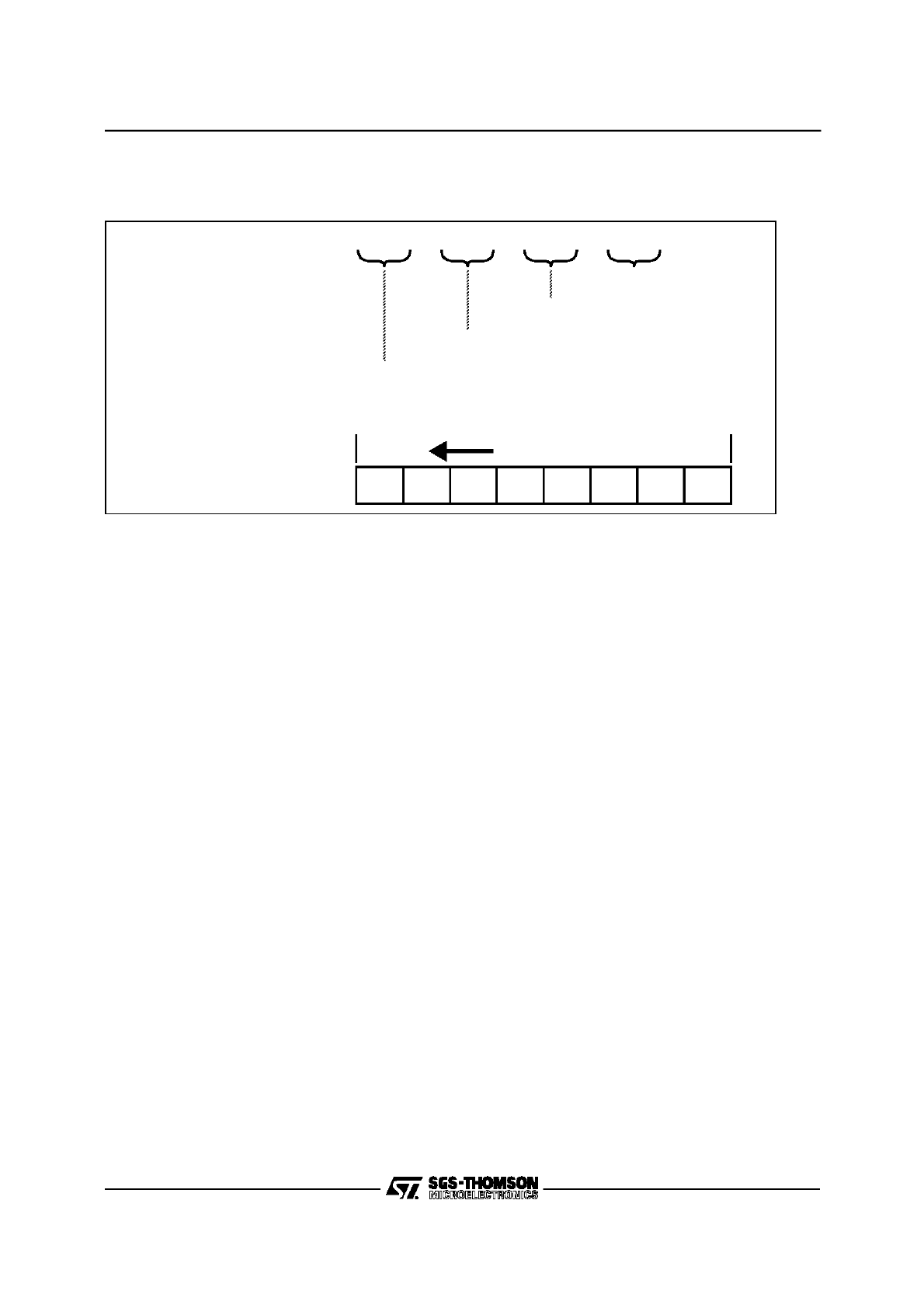
ST10 Programming Manual
40/124
Figure 3. Instruction Format Representation
Notes on the ATOMIC and EXTended Instructions
These instructions (ATOMIC, EXTR, EXTP, EXTS, EXTPR, EXTSR) disable standard and PEC inter-
rupts and class A traps during a sequence of the following 1...4 instructions. The length of the sequence
is determined by an operand (op1 or op2, depending on the instruction). The EXTended instruction ad-
ditionally change the addressing mechanism during this sequence (see detailled instruction description).
The ATOMIC and EXTended instructions become active immediately, so no additional NOPs are re-
quired. All instructions requiring multiple cycles or hold states to be executed are regarded as one in-
struction in this sense. Any instruction type can be used with the ATOMIC and EXTended instructions.
CAUTION: When a Class B trap interupts an ATOMIC or EXTended sequence, this sequence is termi-
nated, the interrupt lock is removed and the standard condition is restored, before the trap routine is ex-
ecuted! The remaining instructions of the terminated sequence that are executed after returning from the
trap routine will run under standard conditions!
CAUTION: Be careful, when using the ATOMIC and EXTended instructions with other system control or
branch instructions.
CAUTION: Be careful, when using nested ATOMIC and EXTended instructions. There is ONE counter
to control the length of such a sequence, ie. issuing an ATOMIC or EXTended instruction within a se-
quence will reload the counter with value of the new instruction.
Note: The ATOMIC and EXTended instructions are not available in the ST10X166 devices.
The following pages of this section contain a detailled description of each instruction of the ST10 in al-
phabetical order.
Bits in ascending order LSB
MSB
Representation in the
Assembler Listing:
N2N1
N4N3
N6N5
N8N7
High Byte 2nd word
Low Byte 2nd word
High Byte 1st word
Low Byte 1st word
Internal Organization:
N8
N7
N6
N5
N4
N3
N2
N1
INSTRUCTION SET (cont’d)

ST10 Programming Manual
41/124
ADD
Integer Addition
ADD
Syntax
ADD
op1, op2
Operation
(op1)
←
(op1) + (op2)
Data Types
WORD
Description
Performs a 2’s complement binary addition of the source operand specified by
op2 and the destination operand specified by op1. The sum is then stored in
op1.
E
Set if the value of op2 represents the lowest possible negative number.
Cleared otherwise. Used to signal the end of a table.
Z
Set if result equals zero. Cleared otherwise.
V
Set if an arithmetic overflow occurred, ie. the result cannot be
represented in the specified data type. Cleared otherwise.
C
Set if a carry is generated from the most significant bit of the specified
data type. Cleared otherwise.
N
Set if the most significant bit of the result is set. Cleared otherwise.
Addressing Modes
Mnemonic
Format
Bytes
ADD
Rw
n
, Rw
m
00 nm
2
ADD
Rw
n
, [Rw
i
]
08 n:10ii
2
ADD
Rw
n
, [Rw
i
+]
08 n:11ii
2
ADD
Rw
n
, #data
3
08 n:0###
2
ADD
reg, #data
16
06 RR ## ##
4
ADD
reg, mem
02 RR MM MM
4
ADD
mem, reg
04 RR MM MM
4
Condition Flags
E
Z
V
C
N
*
*
*
*
*

ST10 Programming Manual
42/124
ADDB
Integer Addition
ADDB
Syntax
ADDB
op1, op2
Operation
(op1)
←
(op1) + (op2)
Data Types
BYTE
Description
Performs a 2’s complement binary addition of the source operand specified by
op2 and the destination operand specified by op1. The sum is then stored in
op1.
E
Set if the value of op2 represents the lowest possible negative number.
Cleared otherwise. Used to signal the end of a table.
Z
Set if result equals zero. Cleared otherwise.
V
Set if an arithmetic overflow occurred, ie. the result cannot be
represented in the specified data type. Cleared otherwise.
C
Set if a carry is generated from the most significant bit of the specified
data type. Cleared otherwise.
N
Set if the most significant bit of the result is set. Cleared otherwise.
Addressing Modes
Mnemonic
Format
Bytes
ADDB
Rb
n
, Rb
m
01 nm
2
ADDB
Rb
n
, [Rw
i
]
09 n:10ii
2
ADDB
Rb
n
, [Rw
i
+]
09 n:11ii
2
ADDB
Rb
n
, #data
3
09 n:0###
2
ADDB
reg, #data
16
07 RR ## ##
4
ADDB
reg, mem
03 RR MM MM
4
ADDB
mem, reg
05 RR MM MM
4
Condition Flags
E
Z
V
C
N
*
*
*
*
*

ST10 Programming Manual
43/124
ADDC
Integer Addition with Carry
ADDC
Syntax
ADDC
op1, op2
Operation
(op1)
←
(op1) + (op2) + (C)
Data Types
WORD
Description
Performs a 2’s complement binary addition of the source operand specified by
op2, the destination operand specified by op1 and the previously generated
carry bit. The sum is then stored in op1. This instruction can be used to perform
multiple precision arithmetic.
E
Set if the value of op2 represents the lowest possible negative number.
Cleared otherwise. Used to signal the end of a table.
Z
Set if result equals zero and previous Z flag was set. Cleared
otherwise.
V
Set if an arithmetic overflow occurred, ie. the result cannot be
represented in the specified data type. Cleared otherwise.
C
Set if a carry is generated from the most significant bit of the specified
data type. Cleared otherwise.
N
Set if the most significant bit of the result is set. Cleared otherwise.
Addressing Modes
Mnemonic
Format
Bytes
ADDC
Rw
n
, Rw
m
10 nm
2
ADDC
Rw
n
, [Rw
i
]
18 n:10ii
2
ADDC
Rw
n
, [Rw
i
+]
18 n:11ii
2
ADDC
Rw
n
, #data
3
18 n:0###
2
ADDC
reg, #data
16
16 RR ## ##
4
ADDC
reg, mem
12 RR MM MM
4
ADDC
mem, reg
14 RR MM MM
4
Condition Flags
E
Z
V
C
N
*
S
*
*
*

ST10 Programming Manual
44/124
ADDBC
Integer Addition with Carry
ADDBC
Syntax
ADDBC
op1, op2
Operation
(op1)
←
(op1) + (op2) + (C)
Data Types
BYTE
Description
Performs a 2’s complement binary addition of the source operand specified by
op2, the destination operand specified by op1 and the previously generated
carry bit. The sum is then stored in op1. This instruction can be used to perform
multiple precision arithmetic.
E
Set if the value of op2 represents the lowest possible negative number.
Cleared otherwise. Used to signal the end of a table.
Z
Set if result equals zero and previous Z flag was set.. Cleared
otherwise.
V
Set if an arithmetic overflow occurred, ie. the result cannot be
represented in the specified data type. Cleared otherwise.
C
Set if a carry is generated from the most significant bit of the specified
data type. Cleared otherwise.
N
Set if the most significant bit of the result is set. Cleared otherwise.
Addressing Modes
Mnemonic
Format
Bytes
ADDCB
Rb
n
, Rb
m
11 nm
2
ADDCB
Rb
n
, [Rw
i
]
19 n:10ii
2
ADDCB
Rb
n
, [Rw
i
+]
19 n:11ii
2
ADDCB
Rb
n
, #data
3
19 n:0###
2
ADDCB
reg, #data
16
17 RR ## ##
4
ADDCB
reg, mem
13 RR MM MM
4
ADDCB
mem, reg
15 RR MM MM
4
Condition Flags
E
Z
V
C
N
*
S
*
*
*

ST10 Programming Manual
45/124
AND
Logical AND
AND
Syntax
AND
op1, op2
Operation
(op1)
←
(op1)
∧
(op2)
Data Types
WORD
Description
Performs a bitwise logical AND of the source operand specified by op2 and the
destination operand specified by op1. The result is then stored in op1.
E
Set if the value of op2 represents the lowest possible negative number.
Cleared otherwise. Used to signal the end of a table.
Z
Set if result equals zero. Cleared otherwise.
V
Always cleared.
C
Always cleared.
N
Set if the most significant bit of the result is set. Cleared otherwise.
Addressing Modes
Mnemonic
Format
Bytes
AND
Rw
n
, Rw
m
60 nm
2
AND
Rw
n
, [Rw
i
]
68 n:10ii
2
AND
Rw
n
, [Rw
i
+]
68 n:11ii
2
AND
Rw
n
, #data
3
68 n:0###
2
AND
reg, #data
16
66 RR ## ##
4
AND
reg, mem
62 RR MM MM
4
AND
mem, reg
64 RR MM MM
4
Condition Flags
E
Z
V
C
N
*
*
0
0
*

ST10 Programming Manual
46/124
ANDB
Logical AND
ANDB
Syntax
ANDB
op1, op2
Operation
(op1)
←
(op1)
∧
(op2)
Data Types
BYTE
Description
Performs a bitwise logical AND of the source operand specified by op2 and the
destination operand specified by op1. The result is then stored in op1.
E
Set if the value of op2 represents the lowest possible negative number.
Cleared otherwise. Used to signal the end of a table.
Z
Set if result equals zero. Cleared otherwise.
V
Always cleared.
C
Always cleared.
N
Set if the most significant bit of the result is set. Cleared otherwise.
Addressing Modes
Mnemonic
Format
Bytes
ANDB
Rb
n
, Rb
m
61 nm
2
ANDB
Rb
n
, [Rw
i
]
69 n:10ii
2
ANDB
Rb
n
, [Rw
i
+]
69 n:11ii
2
ANDB
Rb
n
, #data
3
69 n:0###
2
ANDB
reg, #data
16
67 RR ## ##
4
ANDB
reg, mem
63 RR MM MM
4
ANDB
mem, reg
65 RR MM MM
4
Condition Flags
E
Z
V
C
N
*
*
0
0
*

ST10 Programming Manual
47/124
ASHR
Arithmetic Shift Right
ASHR
Syntax
ASHR
op1, op2
Operation
(count)
←
(op1)
∧
(op2)
(V)
←
0
(C)
←
0
DO WHILE (count)
≠
0
(V)
←
(C)
∨
(V)
(C)
←
(op1
0
)
(op1
n
)
←
(op1
n+1
) [n=0...14]
(count)
←
(count) - 1
END WHILE
Data Types
WORD
Description
Arithmetically shifts the destination word operand op1 right by as many times as
specified in the source operand op2. To preserve the sign of the original
operand op1, the most significant bits of the result are filled with zeros if the
original MSB was a 0 or with ones if the original MSB was a 1. The Overflow flag
is used as a Rounding flag. The LSB is shifted into the Carry. Only shift values
between 0 and 15 are allowed. When using a GPR as the count control, only the
least significant 4 bits are used.
E
Always cleared.
Z
Set if result equals zero. Cleared otherwise.
V
Set if in any cycle of the shift operation a 1 is shifted out of the carry
flag. Cleared for a shift count of zero.
C
The carry flag is set according to the last LSB shifted out of op1.
Cleared for a shift count of zero.
N
Set if the most significant bit of the result is set. Cleared otherwise.
Addressing Modes
Mnemonic
Format
Bytes
ASHR
Rw
n
, Rw
m
AC nm
2
ASHR
Rw
n
, #data
4
BC #n
2
Condition Flags
E
Z
V
C
N
0
*
S
S
*

ST10 Programming Manual
48/124
ATOMIC
Begin ATOMIC Sequence
ATOMIC
Syntax
ATOMIC
op1
Operation
(count)
←
(op1) [1
≤
op1
≤
4]
Disable interrupts and Class A traps
DO WHILE ((count)
≠
0 AND Class_B_trap_condition
≠
TRUE)
Next Instruction
(count)
←
(count) - 1
END WHILE
(count) = 0
Enable interrupts and traps
Description
Causes standard and PEC interrupts and class A hardware traps to be disabled
for a specified number of instructions. The ATOMIC instruction becomes
immediately active such that no additional NOPs are required.
Depending on the value of op1, the period of validity of the ATOMIC sequence
extends over the sequence of the next 1 to 4 instructions being executed after
the ATOMIC instruction. All instructions requiring multiple cycles or hold states
to be executed are regarded as one instruction in this sense. Any instruction
type can be used with the ATOMIC instruction.
Note
The ATOMIC instruction must be used carefully (see introductory note).
The ATOMIC instruction is not available in the ST10X166 devices.
E
Not affected.
Z
Not affected.
V
Not affected.
C
Not affected.
N
Not affected.
Addressing Modes
Mnemonic
Format
Bytes
ATOMIC
#data
2
D1 :00##-0
2
Condition Flags
E
Z
V
C
N
-
-
-
-
-

ST10 Programming Manual
49/124
BAND
Bit Logical AND
BAND
Syntax
BAND
op1, op2
Operation
(op1)
←
(op1)
∧
(op2)
Data Types
BIT
Description
Performs a single bit logical AND of the source bit specified by op2 and the
destination bit specified by op1. The result is then stored in op1.
E
Always cleared.
Z
Contains the logical NOR of the two specified bits.
V
Contains the logical OR of the two specified bits.
C
Contains the logical AND of the two specified bits.
N
Contains the logical XOR of the two specified bits.
Addressing Modes
Mnemonic
Format
Bytes
BAND bitaddr
Z.z
, bitaddr
Q.q
6A QQ ZZ qz
4
Condition Flags
E
Z
V
C
N
0
NOR
OR
AND
XOR

ST10 Programming Manual
50/124
BCLR
Bit Clear
BCLR
Syntax
BCLR
op1
Operation
(op1)
←
0
Data Types
BIT
Description
CLears the bit specified by op1. This instruction is primarily used for peripheral
and system control.
E
Always cleared.
Z
Contains the logical negation of the previous state of the specified bit.
V
Always cleared.
C
Always cleared.
N
Contains the previous state of the specified bit.
Addressing Modes
Mnemonic
Format
Bytes
BCLR
bitaddr
Q.q
qE QQ
2
Condition Flags
E
Z
V
C
N
0
B
0
0
B

ST10 Programming Manual
51/124
BCMP
Bit to Bit Compare
BCMP
Syntax
BCMP
op1, op2
Operation
(op1)
⇔
(op2)
Data Types
BIT
Description
Performs a single bit comparison of the source bit specified by operand op1 to
the source bit specified by operand op2. No result is written by this instruction.
Only the condition codes are updated.
E
Always cleared.
Z
Contains the logical NOR of the two specified bits.
V
Contains the logical OR of the two specified bits.
C
Contains the logical AND of the two specified bits.
N
Contains the logical XOR of the two specified bits.
Addressing Modes
Mnemonic
Format
Bytes
BCMP
bitaddr
Z.z
, bitaddr
Q.q
2A QQ ZZ qz
4
Condition Flags
E
Z
V
C
N
0
NOR
OR
AND
XOR

ST10 Programming Manual
52/124
BFLDH
Bit Field High Byte
BFLDH
Syntax
BFLDH
op1, op2, op3
Operation
(tmp)
←
(op1)
(high byte (tmp))
←
((high byte (tmp)
∧ ¬
op2)
∨
op3)
(op1)
←
(tmp)
Data Types
WORD
Description
Replaces those bits in the high byte of the destination word operand op1 which
are selected by an ’1’ in the AND mask op2 with the bits at the corresponding
positions in the OR mask specified by op3.
Note
Bits which are masked off by a ’0’ in the AND mask op2 may be unintentionally
altered if the corresponding bit in the OR mask op3 contains a ’1’.
E
Always cleared.
Z
Set if the word result equals zero. Cleared otherwise.
V
Always cleared.
C
Always cleared.
N
Set if the most significant bit of the word result is set. Cleared
otherwise.
Addressing Modes
Mnemonic
Format
Bytes
BFLDH bitoff
Q
, #mask
8
, #data
8
1A QQ ## @@
4
Condition Flags
E
Z
V
C
N
0
*
0
0
*

ST10 Programming Manual
53/124
BFLDL
Bit Field Low Byte
BFLDL
Syntax
BFLDL
op1, op2, op3
Operation
(tmp)
←
(op1)
(low byte (tmp))
←
((low byte (tmp)
∧ ¬
op2)
∨
op3)
(op1)
←
(tmp)
Data Types
WORD
Description
Replaces those bits in the low byte of the destination word operand op1 which
are selected by an ’1’ in the AND mask op2 with the bits at the corresponding
positions in the OR mask specified by op3.
Note
Bits which are masked off by a ’0’ in the AND mask op2 may be unintentionally
altered if the corresponding bit in the OR mask op3 contains a ’1’.
E
Always cleared.
Z
Set if the word result equals zero. Cleared otherwise.
V
Always cleared.
C
Always cleared.
N
Set if the most significant bit of the word result is set. Cleared
otherwise.
Addressing Modes
Mnemonic
Format
Bytes
BFLDL bitoff
Q
, #mask
8
, #data
8
0A QQ ## @@
4
Condition Flags
E
Z
V
C
N
0
*
0
0
*

ST10 Programming Manual
54/124
BMOV
Bit to Bit Move
BMOV
Syntax
BMOV
op1, op2
Operation
(op1)
←
(op2)
Data Types
BIT
Description
Moves a single bit from the source operand specified by op2 into the destination
operand specified by op1. The source bit is examined and the flags are updated
accordingly.
E
Always cleared.
Z
Contains the logical negation of the previous state of the source bit.
V
Always cleared.
C
Always cleared.
N
Contains the previous state of the source bit.
Addressing Modes
Mnemonic
Format
Bytes
BMOV bitaddr
Z.z
, bitaddr
Q.q
4A QQ ZZ qz
4
Condition Flags
E
Z
V
C
N
0
B
0
0
B

ST10 Programming Manual
55/124
BMOVN
Bit to Bit Move and Negate
BMOVN
Syntax
BMOVN
op1, op2
Operation
(op1)
← ¬
(op2)
Data Types
BIT
Description
Moves the complement of a single bit from the source operand specified by op2
into the destination operand specified by op1. The source bit is examined and
the flags are updated accordingly.
E
Always cleared.
Z
Contains the logical negation of the previous state of the source bit.
V
Always cleared.
C
Always cleared.
N
Contains the previous state of the source bit.
Addressing Modes
Mnemonic
Format
Bytes
BMOVN bitaddr
Z.z
, bitaddr
Q.q
3A QQ ZZ qz
4
Condition Flags
E
Z
V
C
N
0
B
0
0
B

ST10 Programming Manual
56/124
BOR
Bit Logical OR
BOR
Syntax
BOR
op1, op2
Operation
(op1)
←
(op1)
∨
(op2)
Data Types
BIT
Description
Performs a single bit logical OR of the source bit specified by operand op2 with
the destination bit specified by operand op1. The ORed result is then stored in
op1.
E
Always cleared.
Z
Contains the logical NOR of the two specified bits.
V
Contains the logical OR of the two specified bits.
C
Contains the logical AND of the two specified bits.
N
Contains the logical XOR of the two specified bits.
Addressing Modes
Mnemonic
Format
Bytes
BOR bitaddr
Z.z
, bitaddr
Q.q
5A QQ ZZ qz
4
Condition Flags
E
Z
V
C
N
0
NOR
OR
AND
XOR

ST10 Programming Manual
57/124
BSET
Bit Set
BSET
Syntax
BSET
op1
Operation
(op1)
←
1
Data Types
BIT
Description
Sets the bit specified by op1. This instruction is primarily used for peripheral and
system control.
E
Always cleared.
Z
Contains the logical negation of the previous state of the specified bit.
V
Always cleared.
C
Always cleared.
N
Contains the previous state of the specified bit.
Addressing Modes
Mnemonic
Format
Bytes
BSET
bitaddr
Q.q
qF QQ
2
Condition Flags
E
Z
V
C
N
0
B
0
0
B

ST10 Programming Manual
58/124
BXOR
Bit Logical XOR
BXOR
Syntax
BXOR
op1, op2
Operation
(op1)
←
(op1)
⊕
(op2)
Data Types
BIT
Description
Performs a single bit logical EXCLUSIVE OR of the source bit specified by
operand op2 with the destination bit specified by operand op1. The XORed
result is then stored in op1.
E
Always cleared.
Z
Contains the logical NOR of the two specified bits.
V
Contains the logical OR of the two specified bits.
C
Contains the logical AND of the two specified bits.
N
Contains the logical XOR of the two specified bits.
Addressing Modes
Mnemonic
Format
Bytes
BXOR bitaddr
Z.z
, bitaddr
Q.q
7A QQ ZZ qz
4
Condition Flags
E
Z
V
C
N
0
NOR
OR
AND
XOR

ST10 Programming Manual
59/124
CALLA
Call Subroutine Absolute
CALLA
Syntax
CALLA
op1, op2
Operation
IF (op1) THEN
(SP)
←
(SP) - 2
((SP))
←
(IP)
(IP)
←
op2
ELSE
next instruction
END IF
Description
If the condition specified by op1 is met, a branch to the absolute memory
location specified by the second operand op2 is taken. The value of the
instruction pointer, IP, is placed onto the system stack. Because the IP always
points to the instruction following the branch instruction, the value stored on the
system stack represents the return address of the calling routine. If the condition
is not met, no action is taken and the next instruction is executed normally.
Condition Codes
See condition code table.
E
Not affected.
Z
Not affected.
V
Not affected.
C
Not affected.
N
Not affected.
Addressing Modes
Mnemonic
Format
Bytes
CALLA
cc, caddr
CA c0 MM MM
4
Condition Flags
E
Z
V
C
N
-
-
-
-
-

ST10 Programming Manual
60/124
CALLI
Call Subroutine Indirect
CALLI
Syntax
CALLI
op1, op2
Operation
IF (op1) THEN
(SP)
←
(SP) - 2
((SP))
←
(IP)
(IP)
←
(op2)
ELSE
next instruction
END IF
Description
If the condition specified by op1 is met, a branch to the location specified
indirectly by the second operand op2 is taken. The value of the instruction
pointer, IP, is placed onto the system stack. Because the IP always points to the
instruction following the branch instruction, the value stored on the system stack
represents the return address of the calling routine. If the condition is not met, no
action is taken and the next instruction is executed normally.
Condition Codes
See condition code table.
E
Not affected.
Z
Not affected.
V
Not affected.
C
Not affected.
N
Not affected.
Addressing Modes
Mnemonic
Format
Bytes
CALLI
cc, [Rw
n
]
AB cn
2
Condition Flags
E
Z
V
C
N
-
-
-
-
-

ST10 Programming Manual
61/124
CALLR
Call Subroutine Relative
CALLR
Syntax
CALLR
op1
Operation
(SP)
←
(SP) - 2
((SP))
←
(IP)
(IP)
←
(IP) + sign_extend (op1)
Description
A branch is taken to the location specified by the instruction pointer, IP, plus the
relative displacement, op1. The displacement is a two’s complement number
which is sign extended and counts the relative distance in words. The value of
the instruction pointer (IP) is placed onto the system stack. Because the IP
always points to the instruction following the branch instruction, the value stored
on the system stack represents the return address of the calling routine. The
value of the IP used in the target address calculation is the address of the
instruction following the CALLR instruction.
Condition Codes
See condition code table.
E
Not affected.
Z
Not affected.
V
Not affected.
C
Not affected.
N
Not affected.
Addressing Modes
Mnemonic
Format
Bytes
CALLR
rel
BB rr
2
Condition Flags
E
Z
V
C
N
-
-
-
-
-

ST10 Programming Manual
62/124
CALLS
Call Inter-Segment Subroutine
CALLS
Syntax
CALLS
op1, op2
Operation
(SP)
←
(SP) - 2
((SP))
←
(CSP)
(SP)
←
(SP) - 2
((SP))
←
(IP)
(CSP)
←
op1
(IP)
←
op1
Description
A branch is taken to the absolute location specified by op2 within the segment
specified by op1. The value of the instruction pointer (IP) is placed onto the
system stack. Because the IP always points to the instruction following the
branch instruction, the value stored on the system stack represents the return
address to the calling routine. The previous value of the CSP is also placed on
the system stack to insure correct return to the calling segment.
Condition Codes
See condition code table.
E
Not affected.
Z
Not affected.
V
Not affected.
C
Not affected.
N
Not affected.
Addressing Modes
Mnemonic
Format
Bytes
CALLS
seg, caddr
DA ss MM MM
4
Condition Flags
E
Z
V
C
N
-
-
-
-
-

ST10 Programming Manual
63/124
CMP
Integer Compare
CMP
Syntax
CMP
op1, op2
Operation
(op1)
⇔
(op2)
Data Types
WORD
Description
The source operand specified by op1 is compared to the source operand
specified by op2 by performing a 2’s complement binary subtraction of op2 from
op1. The flags are set according to the rules of subtraction. The operands
remain unchanged.
E
Set if the value of op2 represents the lowest possible negative number.
Cleared otherwise. Used to signal the end of a table.
Z
Set if result equals zero. Cleared otherwise.
V
Set if an arithmetic underflow occurred, ie. the result cannot be
represented in the specified data type. Cleared otherwise.
C
Set if a borrow is generated. Cleared otherwise.
N
Set if the most significant bit of the result is set. Cleared otherwise.
Addressing Modes
Mnemonic
Format
Bytes
CMP
Rw
n
, Rw
m
40 nm
2
CMP
Rw
n
, [Rw
i
]
48 n:10ii
2
CMP
Rw
n
, [Rw
i
+]
48 n:11ii
2
CMP
Rw
n
, #data
3
48 n:0###
2
CMP
reg, #data
16
46 RR ## ##
4
CMP
reg, mem
42 RR MM MM
4
Condition Flags
E
Z
V
C
N
*
*
*
S
*

ST10 Programming Manual
64/124
CMPB
Integer Compare
CMPB
Syntax
CMPB
op1, op2
Operation
(op1)
⇔
(op2)
Data Types
BYTE
Description
The source operand specified by op1 is compared to the source operand
specified by op2 by performing a 2’s complement binary subtraction of op2 from
op1. The flags are set according to the rules of subtraction. The operands
remain unchanged.
E
Set if the value of op2 represents the lowest possible negative number.
Cleared otherwise. Used to signal the end of a table.
Z
Set if result equals zero. Cleared otherwise.
V
Set if an arithmetic underflow occurred, ie. the result cannot be
represented in the specified data type. Cleared otherwise.
C
Set if a borrow is generated. Cleared otherwise.
N
Set if the most significant bit of the result is set. Cleared otherwise.
Addressing Modes
Mnemonic
Format
Bytes
CMPB
Rb
n
, Rb
m
41 nm
2
CMPB
Rb
n
, [Rw
i
]
49 n:10ii
2
CMPB
Rb
n
, [Rw
i
+]
49 n:11ii
2
CMPB
Rb
n
, #data
3
49 n:0###
2
CMPB
reg, #data
16
47 RR ## ##
4
CMPB
reg, mem
43 RR MM MM
4
Condition Flags
E
Z
V
C
N
*
*
*
S
*

ST10 Programming Manual
65/124
CMPD1
Integer Compare and Decrement by 1
CMPD1
Syntax
CMPD1
op1, op2
Operation
(op1)
⇔
(op2)
(op1)
←
(op1) - 1
Data Types
WORD
Description
This instruction is used to enhance the performance and flexibility of loops. The
source operand specified by op1 is compared to the source operand specified
by op2 by performing a 2’s complement binary subtraction of op2 from op1.
Operand op1 may specify ONLY GPR registers. Once the subtraction has
completed, the operand op1 is decremented by one. Using the set flags, a
branch instruction can then be used in conjunction with this instruction to form
common high level language FOR loops of any range.
E
Set if the value of op2 represents the lowest possible negative number.
Cleared otherwise. Used to signal the end of a table.
Z
Set if result equals zero. Cleared otherwise.
V
Set if an arithmetic underflow occurred, ie. the result cannot be
represented in the specified data type. Cleared otherwise.
C
Set if a borrow is generated. Cleared otherwise.
N
Set if the most significant bit of the result is set. Cleared otherwise.
Addressing Modes
Mnemonic
Format
Bytes
CMPD1
Rw
n
, #data
4
A0 #n
2
CMPD1
Rw
n
, #data
16
A6 Fn ## ##
4
CMPD1
Rw
n
, mem
A2 Fn MM MM
4
Condition Flags
E
Z
V
C
N
*
*
*
S
*

ST10 Programming Manual
66/124
CMPD2
Integer Compare and Decrement by 2
CMPD2
Syntax
CMPD2
op1, op2
Operation
(op1)
⇔
(op2)
(op1)
←
(op1) - 2
Data Types
WORD
Description
This instruction is used to enhance the performance and flexibility of loops. The
source operand specified by op1 is compared to the source operand specified
by op2 by performing a 2’s complement binary subtraction of op2 from op1.
Operand op1 may specify ONLY GPR registers. Once the subtraction has
completed, the operand op1 is decremented by two. Using the set flags, a
branch instruction can then be used in conjunction with this instruction to form
common high level language FOR loops of any range.
E
Set if the value of op2 represents the lowest possible negative number.
Cleared otherwise. Used to signal the end of a table.
Z
Set if result equals zero. Cleared otherwise.
V
Set if an arithmetic underflow occurred, ie. the result cannot be
represented in the specified data type. Cleared otherwise.
C
Set if a borrow is generated. Cleared otherwise.
N
Set if the most significant bit of the result is set. Cleared otherwise.
Addressing Modes
Mnemonic
Format
Bytes
CMPD2
Rw
n
, #data
4
B0 #n
2
CMPD2
Rw
n
, #data
16
B6 Fn ## ##
4
CMPD2
Rw
n
, mem
B2 Fn MM MM
4
Condition Flags
E
Z
V
C
N
*
*
*
S
*

ST10 Programming Manual
67/124
CMPI1
Integer Compare and Increment by 1
CMPI1
Syntax
CMPI1
op1, op2
Operation
(op1)
⇔
(op2)
(op1)
←
(op1) + 1
Data Types
WORD
Description
This instruction is used to enhance the performance and flexibility of loops. The
source operand specified by op1 is compared to the source operand specified
by op2 by performing a 2’s complement binary subtraction of op2 from op1.
Operand op1 may specify ONLY GPR registers. Once the subtraction has
completed, the operand op1 is incremented by one. Using the set flags, a
branch instruction can then be used in conjunction with this instruction to form
common high level language FOR loops of any range.
E
Set if the value of op2 represents the lowest possible negative number.
Cleared otherwise. Used to signal the end of a table.
Z
Set if result equals zero. Cleared otherwise.
V
Set if an arithmetic underflow occurred, ie. the result cannot be
represented in the specified data type. Cleared otherwise.
C
Set if a borrow is generated. Cleared otherwise.
N
Set if the most significant bit of the result is set. Cleared otherwise.
Addressing Modes
Mnemonic
Format
Bytes
CMPI1
Rw
n
, #data
4
80 #n
2
CMPI1
Rw
n
, #data
16
86 Fn ## ##
4
CMPI1
Rw
n
, mem
82 Fn MM MM
4
Condition Flags
E
Z
V
C
N
*
*
*
S
*

ST10 Programming Manual
68/124
CMPI2
Integer Compare and Increment by 2
CMPI2
Syntax
CMPI2
op1, op2
Operation
(op1)
⇔
(op2)
(op1)
←
(op1) + 2
Data Types
WORD
Description
This instruction is used to enhance the performance and flexibility of loops. The
source operand specified by op1 is compared to the source operand specified
by op2 by performing a 2’s complement binary subtraction of op2 from op1.
Operand op1 may specify ONLY GPR registers. Once the subtraction has
completed, the operand op1 is incremented by two. Using the set flags, a
branch instruction can then be used in conjunction with this instruction to form
common high level language FOR loops of any range.
E
Set if the value of op2 represents the lowest possible negative number.
Cleared otherwise. Used to signal the end of a table.
Z
Set if result equals zero. Cleared otherwise.
V
Set if an arithmetic underflow occurred, ie. the result cannot be
represented in the specified data type. Cleared otherwise.
C
Set if a borrow is generated. Cleared otherwise.
N
Set if the most significant bit of the result is set. Cleared otherwise.
Addressing Modes
Mnemonic
Format
Bytes
CMPI2
Rw
n
, #data
4
90 #n
2
CMPI2
Rw
n
, #data
16
96 Fn ## ##
4
CMPI2
Rw
n
, mem
92 Fn MM MM
4
Condition Flags
E
Z
V
C
N
*
*
*
S
*

ST10 Programming Manual
69/124
CPL
Integer One’s Complement
CPL
Syntax
CPL
op1
Operation
(op1)
← ¬
(op1)
Data Types
WORD
Description
Performs a 1’s complement of the source operand specified by op1. The result
is stored back into op1.
E
Set if the value of op1 represents the lowest possible negative number.
Cleared otherwise. Used to signal the end of a table.
Z
Set if result equals zero. Cleared otherwise.
V
Always cleared.
C
Always cleared.
N
Set if the most significant bit of the result is set. Cleared otherwise.
Addressing Modes
Mnemonic
Format
Bytes
CPL
Rw
n
91 n0
2
Condition Flags
E
Z
V
C
N
*
*
0
0
*

ST10 Programming Manual
70/124
CPLB
Integer One’s Complement
CPLB
Syntax
CPL
op1
Operation
(op1)
← ¬
(op1)
Data Types
BYTE
Description
Performs a 1’s complement of the source operand specified by op1. The result
is stored back into op1.
E
Set if the value of op1 represents the lowest possible negative number.
Cleared otherwise. Used to signal the end of a table.
Z
Set if result equals zero. Cleared otherwise.
V
Always cleared.
C
Always cleared.
N
Set if the most significant bit of the result is set. Cleared otherwise.
Addressing Modes
Mnemonic
Format
Bytes
CPLB
Rb
n
B1 n0
2
Condition Flags
E
Z
V
C
N
*
*
0
0
*

ST10 Programming Manual
71/124
DISWDT
Disable Watchdog Timer
DISWDT
Syntax
DISWDT
Operation
Disable the watchdog timer
Description
This instruction disables the watchdog timer. The watchdog timer is enabled by
a reset. The DISWDT instruction allows the watchdog timer to be disabled for
applications which do not require a watchdog function. Following a reset, this
instruction can be executed at any time until either a Service Watchdog Timer
instruction (SRVWDT) or an End of Initialization instruction (EINIT) are
executed. Once one of these instructions has been executed, the DISWDT
instruction will have no effect. To insure that this instruction is not accidentally
executed, it is implemented as a protected instruction.
E
Not affected.
Z
Not affected.
V
Not affected.
C
Not affected.
N
Not affected.
Addressing Modes
Mnemonic
Format
Bytes
DISWDT
A5 5A A5 A5
4
Condition Flags
E
Z
V
C
N
-
-
-
-
-

ST10 Programming Manual
72/124
DIV
16-by-16 Signed Division
DIV
Syntax
DIV
op1
Operation
(MDL)
←
(MDL) / (op1)
(MDH)
←
(MDL) mod (op1)
Data Types
WORD
Description
Performs a signed 16-bit by 16-bit division of the low order word stored in the
MD register by the source word operand op1. The signed quotient is then stored
in the low order word of the MD register (MDL) and the remainder is stored in the
high order word of the MD register ( MDH).
E
Always cleared.
Z
Set if result equals zero. Cleared otherwise.
V
Set if an arithmetic overflow occurred, ie. the result cannot be
represented in a word data type, or if the divisor (op1) was zero.
Cleared otherwise.
C
Always cleared.
N
Set if the most significant bit of the result is set. Cleared otherwise.
Addressing Modes
Mnemonic
Format
Bytes
DIV
Rw
n
4B nn
2
Condition Flags
E
Z
V
C
N
0
*
S
0
*

ST10 Programming Manual
73/124
DIVL
32-by-16 Signed Division
DIVL
Syntax
DIVL
op1
Operation
(MDL)
←
(MD) / (op1)
(MDH)
←
(MD) mod (op1)
Data Types
WORD, DOUBLEWORD
Description
Performs an extended signed 32-bit by 16-bit division of the two words stored in
the MD register by the source word operand op1. The signed quotient is then
stored in the low order word of the MD register (MDL) and the remainder is
stored in the high order word of the MD register ( MDH).
E
Always cleared.
Z
Set if result equals zero. Cleared otherwise.
V
Set if an arithmetic overflow occurred, ie. the result cannot be
represented in a word data type, or if the divisor (op1) was zero.
Cleared otherwise.
C
Always cleared.
N
Set if the most significant bit of the result is set. Cleared otherwise.
Addressing Modes
Mnemonic
Format
Bytes
DIVL
Rw
n
6B nn
2
Condition Flags
E
Z
V
C
N
0
*
S
0
*

ST10 Programming Manual
74/124
DIVLU
32-by-16 Unsigned Division
DIVLU
Syntax
DIVLU
op1
Operation
(MDL)
←
(MD) / (op1)
(MDH)
←
(MD) mod (op1)
Data Types
WORD, DOUBLEWORD
Description
Performs an extended unsigned 32-bit by 16-bit division of the two words stored
in the MD register by the source word operand op1. The unsigned quotient is
then stored in the low order word of the MD register (MDL) and the remainder is
stored in the high order word of the MD register ( MDH).
E
Always cleared.
Z
Set if result equals zero. Cleared otherwise.
V
Set if an arithmetic overflow occurred, ie. the result cannot be
represented in a word data type, or if the divisor (op1) was zero.
Cleared otherwise.
C
Always cleared.
N
Set if the most significant bit of the result is set. Cleared otherwise.
Addressing Modes
Mnemonic
Format
Bytes
DIVLU
Rw
n
7B nn
2
Condition Flags
E
Z
V
C
N
0
*
S
0
*

ST10 Programming Manual
75/124
DIVU
16-by-16 Unsigned Division
DIVU
Syntax
DIVU
op1
Operation
(MDL)
←
(MDL) / (op1)
(MDH)
←
(MDL) mod (op1)
Data Types
WORD
Description
Performs an unsigned 16-bit by 16-bit division of the low order word stored in the
MD register by the source word operand op1. The signed quotient is then stored
in the low order word of the MD register (MDL) and the remainder is stored in the
high order word of the MD register ( MDH).
E
Always cleared.
Z
Set if result equals zero. Cleared otherwise.
V
Set if an arithmetic overflow occurred, ie. the result cannot be
represented in a word data type, or if the divisor (op1) was zero.
Cleared otherwise.
C
Always cleared.
N
Set if the most significant bit of the result is set. Cleared otherwise.
Addressing Modes
Mnemonic
Format
Bytes
DIVU
Rw
n
5B nn
2
Condition Flags
E
Z
V
C
N
0
*
S
0
*

ST10 Programming Manual
76/124
EINIT
End of Initialization
EINIT
Syntax
EINIT
Operation
End of Initialization
Description
This instruction is used to signal the end of the initialization portion of a program.
After a reset, the reset output pin RSTOUT is pulled low. It remains low until the
EINIT instruction has been executed at which time it goes high. This enables the
program to signal the external circuitry that it has successfully initialized the
microcontroller. After the EINIT instruction has been executed, execution of the
Disable Watchdog Timer instruction (DISWDT) has no effect. To insure that this
instruction is not accidentally executed, it is implemented as a protected
instruction.
E
Not affected.
Z
Not affected.
V
Not affected.
C
Not affected.
N
Not affected.
Addressing Modes
Mnemonic
Format
Bytes
EINIT
B5 4A B5 B5
4
Condition Flags
E
Z
V
C
N
-
-
-
-
-

ST10 Programming Manual
77/124
EXTR
Begin EXTended Register Sequence
EXTR
Syntax
EXTR
op1
Operation
(count)
←
(op1) [1
≤
op1
≤
4]
Disable interrupts and Class A traps
SFR_range = Extended
DO WHILE ((count)
≠
0 AND Class_B_trap_condition
≠
TRUE)
Next Instruction
(count)
←
(count) - 1
END WHILE
(count) = 0
SFR_range = Standard
Enable interrupts and traps
Description
Causes all SFR or SFR bit accesses via the ’reg’, ’bitoff’ or ’bitaddr’ addressing
modes being made to the Extended SFR space for a specified number of
instructions. During their execution, both standard and PEC interrupts and class
A hardware traps are locked.
The value of op1 defines the length of the effected instruction sequence.
Note
The EXTR instruction must be used carefully (see introductory note).
The EXTR instruction is not available in the ST10X166 devices.
E
Not affected.
Z
Not affected.
V
Not affected.
C
Not affected.
N
Not affected.
Addressing Modes
Mnemonic
Format
Bytes
EXTR
#data
2
D1 :10##-0
2
Condition Flags
E
Z
V
C
N
-
-
-
-
-

ST10 Programming Manual
78/124
EXTP
Begin EXTended Page Sequence
EXTP
Syntax
EXTP
op1, op2
Operation
(count)
←
(op2) [1
≤
op2
≤
4]
Disable interrupts and Class A traps
Data_Page = (op1)
DO WHILE ((count)
≠
0 AND Class_B_trap_condition
≠
TRUE)
Next Instruction
(count)
←
(count) - 1
END WHILE
(count) = 0
Data_Page = (DPPx)
Enable interrupts and traps
Description
Overrides the standard DPP addressing scheme of the long and indirect
addressing modes for a specified number of instructions. During their execution,
both standard and PEC interrupts and class A hardware traps are locked. The
EXTP instruction becomes immediately active such that no additional NOPs are
required.
For any long (’mem’) or indirect ([...]) address in the EXTP instruction sequence,
the 10-bit page number (address bits A23-A14) is not determined by the
contents of a DPP register but by the value of op1 itself. The 14-bit page offset
(address bits A13-A0) is derived from the long or indirect address as usual.
The value of op2 defines the length of the effected instruction sequence.
Note
The EXTP instruction must be used carefully (see introductory note).
The EXTP instruction is not available in the ST10X166 devices.
E
Not affected.
Z
Not affected.
V
Not affected.
C
Not affected.
N
Not affected.
Addressing Modes
Mnemonic
Format
Bytes
EXTP
Rwm, #data
2
DC :01##-m
2
EXTP
#pag, #data
2
D7 :01##-0 pp 0:00pp
4
Condition Flags
E
Z
V
C
N
-
-
-
-
-

ST10 Programming Manual
79/124
EXTPR
Begin EXTended Page and Register Sequence
EXTPR
Syntax
EXTPR
op1, op2
Operation
(count)
←
(op2) [1
≤
op2
≤
4]
Disable interrupts and Class A traps
Data_Page = (op1) AND SFR_range = Extended
DO WHILE ((count)
≠
0 AND Class_B_trap_condition
≠
TRUE)
Next Instruction
(count)
←
(count) - 1
END WHILE
(count) = 0
Data_Page = (DPPx) AND SFR_range = Standard
Enable interrupts and traps
Description
Overrides the standard DPP addressing scheme of the long and indirect
addressing modes and causes all SFR or SFR bit accesses via the ’reg’, ’bitoff’
or ’bitaddr’ addressing modes being made to the Extended SFR space for a
specified number of instructions. During their execution, both standard and PEC
interrupts and class A hardware traps are locked.
For any long (’mem’) or indirect ([...]) address in the EXTP instruction sequence,
the 10-bit page number (address bits A23-A14) is not determined by the
contents of a DPP register but by the value of op1 itself. The 14-bit page offset
(address bits A13-A0) is derived from the long or indirect address as usual.
The value of op2 defines the length of the effected instruction sequence.
Note
The EXTPR instruction must be used carefully (see introductory note).
The EXTPR instruction is not available in the ST10X166 devices.
E
Not affected.
Z
Not affected.
V
Not affected.
C
Not affected.
N
Not affected.
Addressing Modes
Mnemonic
Format
Bytes
EXTPR
Rwm, #data
2
DC :11##-m
2
EXTPR
#pag, #data
2
D7 :11##-0 pp 0:00pp
4
Condition Flags
E
Z
V
C
N
-
-
-
-
-

ST10 Programming Manual
80/124
EXTS
Begin EXTended Segment Sequence
EXTS
Syntax
EXTS
op1, op2
Operation
(count)
←
(op2) [1
≤
op2
≤
4]
Disable interrupts and Class A traps
Data_Segment = (op1)
DO WHILE ((count)
≠
0 AND Class_B_trap_condition
≠
TRUE)
Next Instruction
(count)
←
(count) - 1
END WHILE
(count) = 0
Data_Page = (DPPx)
Enable interrupts and traps
Description
Overrides the standard DPP addressing scheme of the long and indirect
addressing modes for a specified number of instructions. During their execution,
both standard and PEC interrupts and class A hardware traps are locked. The
EXTS instruction becomes immediately active such that no additional NOPs are
required.
For any long (’mem’) or indirect ([...]) address in an EXTS instruction sequence,
the value of op1 determines the 8-bit segment (address bits A23-A16) valid for
the corresponding data access. The long or indirect address itself represents
the 16-bit segment offset (address bits A15-A0).
The value of op2 defines the length of the effected instruction sequence.
Note
The EXTS instruction must be used carefully (see introductory note).
The EXTS instruction is not available in the ST10X166 devices.
E
Not affected.
Z
Not affected.
V
Not affected.
C
Not affected.
N
Not affected.
Addressing Modes
Mnemonic
Format
Bytes
EXTS
Rwm, #data
2
DC :00##-m
2
EXTS
#seg, #data
2
D7 :00##-0 ss 00
4
Condition Flags
E
Z
V
C
N
-
-
-
-
-

ST10 Programming Manual
81/124
EXTSR
Begin EXTended Segment and Register Sequence
EXTSR
Syntax
EXTSR
op1, op2
Operation
(count)
←
(op2) [1
≤
op2
≤
4]
Disable interrupts and Class A traps
Data_Segment = (op1) AND SFR_range = Extended
DO WHILE ((count)
≠
0 AND Class_B_trap_condition
≠
TRUE)
Next Instruction
(count)
←
(count) - 1
END WHILE
(count) = 0
Data_Page = (DPPx) AND SFR_range = Standard
Enable interrupts and traps
Description
Overrides the standard DPP addressing scheme of the long and indirect
addressing modes and causes all SFR or SFR bit accesses via the ’reg’, ’bitoff’
or ’bitaddr’ addressing modes being made to the Extended SFR space for a
specified number of instructions. During their execution, both standard and PEC
interrupts and class A hardware traps are locked. The EXTSR instruction
becomes immediately active such that no additional NOPs are required.
For any long (’mem’) or indirect ([...]) address in an EXTSR instruction
sequence, the value of op1 determines the 8-bit segment (address bits A23-
A16) valid for the corresponding data access. The long or indirect address itself
represents the 16-bit segment offset (address bits A15-A0).
The value of op2 defines the length of the effected instruction sequence.
Note
The EXTSR instruction must be used carefully (see introductory note).
The EXTSR instruction is not available in the ST10X166 devices.
E
Not affected.
Z
Not affected.
V
Not affected.
C
Not affected.
N
Not affected.
Addressing Modes
Mnemonic
Format
Bytes
EXTSR
Rwm, #data
2
DC :10##-m
2
EXTSR
#seg, #data
2
D7 :10##-0 ss 00
4
Condition Flags
E
Z
V
C
N
-
-
-
-
-

ST10 Programming Manual
82/124
IDLE
Enter Idle Mode
IDLE
Syntax
IDLE
Operation
Enter Idle Mode
Description
This instruction causes the part to enter the idle mode. In this mode, the CPU is
powered down while the peripherals remain running. It remains powered down
until a peripheral interrupt or external interrupt occurs. To insure that this
instruction is not accidentally executed, it is implemented as a protected
instruction.
E
Not affected.
Z
Not affected.
V
Not affected.
C
Not affected.
N
Not affected.
Addressing Modes
Mnemonic
Format
Bytes
IDLE
87 78 87 87
4
Condition Flags
E
Z
V
C
N
-
-
-
-
-

ST10 Programming Manual
83/124
JB
Relative Jump if Bit Set
JB
Syntax
JB
op1, op2
Operation
IF (op1) = 1 THEN
(IP)
←
(IP) + sign_extend (op2)
ELSE
Next Instruction
END IF
Data Types
BIT
Description
If the bit specified by op1 is set, program execution continues at the location of
the instruction pointer, IP, plus the specified displacement, op2. The
displacement is a two’s complement number which is sign extended and counts
the relative distance in words. The value of the IP used in the target address
calculation is the address of the instruction following the JB instruction. If the
specified bit is clear, the instruction following the JB instruction is executed.
E
Not affected.
Z
Not affected.
V
Not affected.
C
Not affected.
N
Not affected.
Addressing Modes
Mnemonic
Format
Bytes
JB
bitaddr
Q.q
, rel
8A QQ rr q0
4
Condition Flags
E
Z
V
C
N
-
-
-
-
-
ST10 Programming Manual
84/124
JBC
Relative Jump if Bit Set and Clear Bit
JBC
Syntax
JBC
op1, op2
Operation
IF (op1) = 1 THEN
(op1) = 0
(IP)
←
(IP) + sign_extend (op2)
ELSE
Next Instruction
END IF
Data Types
BIT
Description
If the bit specified by op1 is set, program execution continues at the location of
the instruction pointer, IP, plus the specified displacement, op2. The bit
specified by op1 is cleared, allowing implementation of semaphore operations.
The displacement is a two’s complement number which is sign extended and
counts the relative distance in words. The value of the IP used in the target
address calculation is the address of the instruction following the JBC
instruction. If the specified bit was clear, the instruction following the JBC
instruction is executed.
E
Not affected.
Z
Contains logical negation of the previous state of the specified bit.
V
Not affected.
C
Not affected.
N
Contains the previous state of the specified bit.
Addressing Modes
Mnemonic
Format
Bytes
JBC
bitaddr
Q.q
, rel
AA QQ rr q0
4
Condition Flags
E
Z
V
C
N
-
B
-
-
B

ST10 Programming Manual
85/124
JMPA
Absolute Conditional Jump
JMPA
Syntax
JMPA
op1, op2
Operation
IF (op1) = 1 THEN
(IP)
←
op2
ELSE
Next Instruction
END IF
Description
If the condition specified by op1 is met, a branch to the absolute address
specified by op2 is taken. If the condition is not met, no action is taken, and the
instruction following the JMPA instruction is executed normally.
Condition Codes
See condition code table.
E
Not affected.
Z
Not affected.
V
Not affected.
C
Not affected.
N
Not affected.
Addressing Modes
Mnemonic
Format
Bytes
JMPA
cc, caddr
EA c0 MM MM
4
Condition Flags
E
Z
V
C
N
-
-
-
-
-

ST10 Programming Manual
86/124
JMPI
Indirect Conditional Jump
JMPI
Syntax
JMPI
op1, op2
Operation
IF (op1) = 1 THEN
(IP)
←
(op2)
ELSE
Next Instruction
END IF
Description
If the condition specified by op1 is met, a branch to the absolute address
specified by op2 is taken. If the condition is not met, no action is taken, and the
instruction following the JMPI instruction is executed normally.
Condition Codes
See condition code table.
E
Not affected.
Z
Not affected.
V
Not affected.
C
Not affected.
N
Not affected.
Addressing Modes
Mnemonic
Format
Bytes
JMPI
cc, [Rw
n
]
9C cn
2
Condition Flags
E
Z
V
C
N
-
-
-
-
-

ST10 Programming Manual
87/124
JMPR
Relative Conditional Jump
JMPR
Syntax
JMPR
op1, op2
Operation
IF (op1) = 1 THEN
(IP)
←
(IP) + sign_extend (op2)
ELSE
Next Instruction
END IF
Description
If the condition specified by op1 is met, program execution continues at the
location of the instruction pointer, IP, plus the specified displacement, op2. The
displacement is a two’s complement number which is sign extended and counts
the relative distance in words. The value of the IP used in the target address
calculation is the address of the instruction following the JMPR instruction. If the
specified condition is not met, program execution continues normally with the
instruction following the JMPR instruction.
Condition Codes
See condition code table.
E
Not affected.
Z
Not affected.
V
Not affected.
C
Not affected.
N
Not affected.
Addressing Modes
Mnemonic
Format
Bytes
JMPR
cc, rel
cD rr
2
Condition Flags
E
Z
V
C
N
-
-
-
-
-

ST10 Programming Manual
88/124
JMPS
Absolute Inter-Segment Jump
JMPS
Syntax
JMPS
op1, op2
Operation
(CSP)
←
op1
(IP)
←
op2
Description
Branches unconditionally to the absolute address specified by op2 within the
segment specified by op1.
E
Not affected.
Z
Not affected.
V
Not affected.
C
Not affected.
N
Not affected.
Addressing Modes
Mnemonic
Format
Bytes
JMPS
seg, caddr
FA ss MM MM
4
Condition Flags
E
Z
V
C
N
-
-
-
-
-

ST10 Programming Manual
89/124
JNB
Relative Jump if Bit Clear
JNB
Syntax
JNB
op1, op2
Operation
IF (op1) = 0 THEN
(IP)
←
(IP) + sign_extend (op2)
ELSE
Next Instruction
END IF
Data Types
BIT
Description
If the bit specified by op1 is clear, program execution continues at the location
of the instruction pointer, IP, plus the specified displacement, op2. The
displacement is a two’s complement number which is sign extended and counts
the relative distance in words. The value of the IP used in the target address
calculation is the address of the instruction following the JNB instruction. If the
specified bit is set, the instruction following the JNB instruction is executed.
E
Not affected.
Z
Not affected.
V
Not affected.
C
Not affected.
N
Not affected.
Addressing Modes
Mnemonic
Format
Bytes
JNB
bitaddr
Q.q
, rel
9A QQ rr q0
4
Condition Flags
E
Z
V
C
N
-
-
-
-
-

ST10 Programming Manual
90/124
JNBS
Relative Jump if Bit Clear and Set Bit
JNBS
Syntax
JNBS
op1, op2
Operation
IF (op1) = 0 THEN
(op1) = 1
(IP)
←
(IP) + sign_extend (op2)
ELSE
Next Instruction
END IF
Data Types
BIT
Description
If the bit specified by op1 is clear, program execution continues at the location
of the instruction pointer, IP, plus the specified displacement, op2. The bit
specified by op1 is set, allowing implementation of semaphore operations. The
displacement is a two’s complement number which is sign extended and counts
the relative distance in words. The value of the IP used in the target address
calculation is the address of the instruction following the JNBS instruction. If the
specified bit was set, the instruction following the JNBS instruction is executed.
E
Not affected.
Z
Contains logical negation of the previous state of the specified bit.
V
Not affected.
C
Not affected.
N
Contains the previous state of the specified bit.
Addressing Modes
Mnemonic
Format
Bytes
JNBS
bitaddr
Q.q
, rel
BA QQ rr q0
4
Condition Flags
E
Z
V
C
N
-
B
-
-
B

ST10 Programming Manual
91/124
MOV
Move Data
MOV
Syntax
MOV
op1, op2
Operation
(op1)
←
(op2)
Data Types
WORD
Description
Moves the contents of the source operand specified by op2 to the location
specified by the destination operand op1. The contents of the moved data is
examined, and the condition codes are updated accordingly.
E
Set if the value of op2 represents the lowest possible negative number.
Cleared otherwise. Used to signal the end of a table.
Z
Set if the value of the source operand op2 equals zero. Cleared
otherwise.
V
Not affected.
C
Not affected.
N
Set if the most significant bit of the source operand op2 is set. Cleared
otherwise.
Addressing Modes
Mnemonic
Format
Bytes
MOV
Rw
n
, Rw
m
F0 nm
2
MOV
Rw
n
, #data
4
E0 #n
2
MOV
reg, #data
16
E6 RR ## ##
4
MOV
Rw
n
, [Rw
m
]
A8 nm
2
MOV
Rw
n
, [Rw
m
+]
98 nm
2
MOV
[Rw
m
], Rw
n
B8 nm
2
MOV
[-Rw
m
], Rw
n
88 nm
2
MOV
[Rw
n
], [Rw
m
]
C8 nm
2
MOV
[Rw
n
+], [Rw
m
]
D8 nm
2
MOV
[Rw
n
], [Rw
m
+]
E8 nm
2
MOV
Rw
n
, [Rw
m
+#data
16
]
D4 nm ## ##
4
MOV
[Rw
m
+#data
16
], Rw
n
C4 nm ## ##
4
MOV
[Rw
n
], mem
84 0n MM MM
4
MOV
mem, [Rw
n
]
94 0n MM MM
4
MOV
reg, mem
F2 RR MM MM
4
MOV
mem, reg
F6 RR MM MM
4
Condition Flags
E
Z
V
C
N
*
*
-
-
*

ST10 Programming Manual
92/124
MOVB
Move Data
MOVB
Syntax
MOVB
op1, op2
Operation
(op1)
←
(op2)
Data Types
BYTE
Description
Moves the contents of the source operand specified by op2 to the location
specified by the destination operand op1. The contents of the moved data is
examined, and the condition codes are updated accordingly.
E
Set if the value of op2 represents the lowest possible negative number.
Cleared otherwise. Used to signal the end of a table.
Z
Set if the value of the source operand op2 equals zero. Cleared
otherwise.
V
Not affected.
C
Not affected.
N
Set if the most significant bit of the source operand op2 is set. Cleared
otherwise.
Addressing Modes
Mnemonic
Format
Bytes
MOVB
Rb
n
, Rb
m
F1 nm
2
MOVB
Rb
n
, #data
4
E1 #n
2
MOVB
reg, #data
16
E7 RR ## ##
4
MOVB
Rb
n
, [Rw
m
]
A9 nm
2
MOVB
Rb
n
, [Rw
m
+]
99 nm
2
MOVB
[Rw
m
], Rb
n
B9 nm
2
MOVB
[-Rw
m
], Rb
n
89 nm
2
MOVB
[Rw
n
], [Rw
m
]
C9 nm
2
MOVB
[Rw
n
+], [Rw
m
]
D9 nm
2
MOVB
[Rw
n
], [Rw
m
+]
E9 nm
2
MOVB
Rb
n
, [Rw
m
+#data
16
]
F4 nm ## ##
4
MOVB
[Rw
m
+#data
16
], Rb
n
E4 nm ## ##
4
MOVB
[Rw
n
], mem
A4 0n MM MM
4
MOVB
mem, [Rw
n
]
B4 0n MM MM
4
MOVB
reg, mem
F3 RR MM MM
4
MOVB
mem, reg
F7 RR MM MM
4
Condition Flags
E
Z
V
C
N
*
*
-
-
*

ST10 Programming Manual
93/124
MOVBS
Move Byte Sign Extend
MOVBS
Syntax
MOVBS
op1, op2
Operation
(low byte op1)
←
(op2)
IF (op2
7
) = 1 THEN
(high byte op1)
←
FF
H
ELSE
(high byte op1)
←
00
H
END IF
Data Types
WORD, BYTE
Description
Moves and sign extends the contents of the source byte specified by op2 to the
word location specified by the destination operand op1. The contents of the
moved data is examined, and the condition codes are updated accordingly.
E
Always cleared.
Z
Set if the value of the source operand op2 equals zero. Cleared
otherwise.
V
Not affected.
C
Not affected.
N
Set if the most significant bit of the source operand op2 is set. Cleared
otherwise.
Addressing Modes
Mnemonic
Format
Bytes
MOVBS
Rw
n
, Rb
m
D0 mn
2
MOVBS
reg, mem
D2 RR MM MM
4
MOVBS
mem, reg
D5 RR MM MM
4
Condition Flags
E
Z
V
C
N
0
*
-
-
*

ST10 Programming Manual
94/124
MOVBZ
Move Byte Zero Extend
MOVBZ
Syntax
MOVBZ
op1, op2
Operation
(low byte op1)
←
(op2)
(high byte op1)
←
00
H
Data Types
WORD, BYTE
Description
Moves and zero extends the contents of the source byte specified by op2 to the
word location specified by the destination operand op1. The contents of the
moved data is examined, and the condition codes are updated accordingly.
E
Always cleared.
Z
Set if the value of the source operand op2 equals zero. Cleared
otherwise.
V
Not affected.
C
Not affected.
N
Always cleared.
Addressing Modes
Mnemonic
Format
Bytes
MOVBZ
Rw
n
, Rb
m
C0 mn
2
MOVBZ
reg, mem
C2 RR MM MM
4
MOVBZ
mem, reg
C5 RR MM MM
4
Condition Flags
E
Z
V
C
N
0
*
-
-
0

ST10 Programming Manual
95/124
MUL
Signed Multiplication
MUL
Syntax
MUL
op1, op2
Operation
(MD)
←
(op1) * (op2)
Data Types
WORD
Description
Performs a 16-bit by 16-bit signed multiplication using the two words specified
by operands op1 and op2 respectively. The signed 32-bit result is placed in the
MD register.
E
Always cleared.
Z
Set if the result equals zero. Cleared otherwise.
V
This bit is set if the result cannot be represented in a word data type.
Cleared otherwise.
C
Always cleared.
N
Set if the most significant bit of the result is set. Cleared otherwise.
Addressing Modes
Mnemonic
Format
Bytes
MUL
Rw
n
, Rw
m
0B nm
2
Condition Flags
E
Z
V
C
N
0
*
S
0
0

ST10 Programming Manual
96/124
MULU
Unsigned Multiplication
MULU
Syntax
MULU
op1, op2
Operation
(MD)
←
(op1) * (op2)
Data Types
WORD
Description
Performs a 16-bit by 16-bit
unsigned multiplication using the two words
specified by operands op1 and op2 respectively. The unsigned 32-bit result is
placed in the MD register.
E
Always cleared.
Z
Set if the result equals zero. Cleared otherwise.
V
This bit is set if the result cannot be represented in a word data type.
Cleared otherwise.
C
Always cleared.
N
Set if the most significant bit of the result is set. Cleared otherwise.
Addressing Modes
Mnemonic
Format
Bytes
MULU
Rw
n
, Rw
m
1foB nm
2
Condition Flags
E
Z
V
C
N
0
*
S
0
0

ST10 Programming Manual
97/124
NEG
Integer Two’s Complement
NEG
Syntax
NEG
op1
Operation
(op1)
←
0 - (op1)
Data Types
WORD
Description
Performs a binary 2’s complement of the source operand specified by op1. The
result is then stored in op1.
E
Set if the value of op1 represents the lowest possible negative number.
Cleared otherwise. Used to signal the end of a table.
Z
Set if result equals zero. Cleared otherwise.
V
Set if an arithmetic underflow occurred, ie. the result cannot be
represented in the specified data type. Cleared otherwise.
C
Set if a borrow is generated. Cleared otherwise.
N
Set if the most significant bit of the result is set. Cleared otherwise.
Addressing Modes
Mnemonic
Format
Bytes
NEG
Rw
n
81 n0
2
Condition Flags
E
Z
V
C
N
*
*
*
S
*

ST10 Programming Manual
98/124
NEGB
Integer Two’s Complement
NEGB
Syntax
NEGB
op1
Operation
(op1)
←
0 - (op1)
Data Types
BYTE
Description
Performs a binary 2’s complement of the source operand specified by op1. The
result is then stored in op1.
E
Set if the value of op1 represents the lowest possible negative number.
Cleared otherwise. Used to signal the end of a table.
Z
Set if result equals zero. Cleared otherwise.
V
Set if an arithmetic underflow occurred, ie. the result cannot be
represented in the specified data type. Cleared otherwise.
C
Set if a borrow is generated. Cleared otherwise.
N
Set if the most significant bit of the result is set. Cleared otherwise.
Addressing Modes
Mnemonic
Format
Bytes
NEGB
Rb
n
A1 n0
2
Condition Flags
E
Z
V
C
N
*
*
*
S
*

ST10 Programming Manual
99/124
NOP
No Operation
NOP
Syntax
NOP
Operation
No Operation
Description
This instruction causes a null operation to be performed. A null operation
causes no change in the status of the flags.
E
Not affected.
Z
Not affected.
V
Not affected.
C
Not affected.
N
Not affected.
Addressing Modes
Mnemonic
Format
Bytes
NOP
CC 00
2
Condition Flags
E
Z
V
C
N
-
-
-
-
-

ST10 Programming Manual
100/124
OR
Logical OR
OR
Syntax
OR
op1, op2
Operation
(op1)
←
(op1)
∨
(op2)
Data Types
WORD
Description
Performs a bitwise logical OR of the source operand specified by op2 and the
destination operand specified by op1. The result is then stored in op1.
E
Set if the value of op2 represents the lowest possible negative number.
Cleared otherwise. Used to signal the end of a table.
Z
Set if result equals zero. Cleared otherwise.
V
Always cleared.
C
Always cleared.
N
Set if the most significant bit of the result is set. Cleared otherwise.
Addressing Modes
Mnemonic
Format
Bytes
OR
Rw
n
, Rw
m
70 nm
2
OR
Rw
n
, [Rw
i
]
78 n:10ii
2
OR
Rw
n
, [Rw
i
+]
78 n:11ii
2
OR
Rw
n
, #data
3
78 n:0###
2
OR
reg, #data
16
76 RR ## ##
4
OR
reg, mem
72 RR MM MM
4
OR
mem, reg
74 RR MM MM
4
Condition Flags
E
Z
V
C
N
*
*
0
0
*

ST10 Programming Manual
101/124
ORB
Logical OR
ORB
Syntax
ORB
op1, op2
Operation
(op1)
←
(op1)
∨
(op2)
Data Types
BYTE
Description
Performs a bitwise logical OR of the source operand specified by op2 and the
destination operand specified by op1. The result is then stored in op1.
E
Set if the value of op2 represents the lowest possible negative number.
Cleared otherwise. Used to signal the end of a table.
Z
Set if result equals zero. Cleared otherwise.
V
Always cleared.
C
Always cleared.
N
Set if the most significant bit of the result is set. Cleared otherwise.
Addressing Modes
Mnemonic
Format
Bytes
ORB
Rb
n
, Rb
m
71 nm
2
ORB
Rb
n
, [Rw
i
]
79 n:10ii
2
ORB
Rb
n
, [Rw
i
+]
79 n:11ii
2
ORB
Rb
n
, #data
3
79 n:0###
2
ORB
reg, #data
16
77 RR ## ##
4
ORB
reg, mem
73 RR MM MM
4
ORB
mem, reg
75 RR MM MM
4
Condition Flags
E
Z
V
C
N
*
*
0
0
*

ST10 Programming Manual
102/124
PCALL
Push Word and Call Subroutine Absolute
PCALL
Syntax
PCALL
op1, op2
Operation
(tmp)
←
(op1)
(SP)
←
(SP) - 2
((SP))
←
(tmp)
(SP)
←
(SP) - 2
((SP))
←
(IP)
(IP)
←
op2
Data Types
WORD
Description
Pushes the word specified by operand op1 and the value of the instruction
pointer, IP, onto the system stack, and branches to the absolute memory
location specified by the second operand op2. Because IP always points to the
instruction following the branch instruction, the value stored on the system stack
represents the return address of the calling routine.
E
Set if the value of the pushed operand op1 represents the lowest
possible negative number. Cleared otherwise. Used to signal the end
of a table.
Z
Set if the value of the pushed operand op1 equals zero. Cleared
otherwise.
V
Not affected.
C
Not affected.
N
Set if the most significant bit of the pushed operand op1 is set. Cleared
otherwise.
Addressing Modes
Mnemonic
Format
Bytes
PCALL
reg, caddr
E2 RR MM MM
4
Condition Flags
E
Z
V
C
N
*
*
-
-
*

ST10 Programming Manual
103/124
POP
Pop Word from System Stack
POP
Syntax
POP
op1
Operation
(tmp)
←
((SP))
(SP)
←
(SP) + 2
(op1)
←
(tmp)
Data Types
WORD
Description
Pops one word from the system stack specified by the Stack Pointer into the
operand specified by op1. The Stack Pointer is then incremented by two.
E
Set if the value of the popped word represents the lowest possible
negative number. Cleared otherwise. Used to signal the end of a table.
Z
Set if the value of the popped word equals zero. Cleared otherwise.
V
Not affected.
C
Not affected.
N
Set if the most significant bit of the popped word is set. Cleared
otherwise.
Addressing Modes
Mnemonic
Format
Bytes
POP
reg
FC RR
2
Condition Flags
E
Z
V
C
N
*
*
-
-
*

ST10 Programming Manual
104/124
PRIOR
Prioritize Register
PRIOR
Syntax
PRIOR
op1, op2
Operation
(tmp)
←
(op2)
(count)
←
0
DO WHILE (tmp
15
)
≠
1 AND (count)
≠
15 AND (op2)
≠
0
(tmp
n
)
←
(tmp
n-
1)
(count)
←
(count) - 1
END WHILE
(op1)
←
(count)
Data Types
WORD
Description
This instruction stores a count value in the word operand specified by op1
indicating the number of single bit shifts required to normalize the operand op2
so that its MSB is equal to one. If the source operand op2 equals zero, a zero is
written to operand op1 and the zero flag is set. Otherwise the zero flag is
cleared.
E
Always cleared.
Z
Set if the source operand op2 equals zero. Cleared otherwise.
V
Always cleared.
C
Always cleared.
N
Always cleared.
Addressing Modes
Mnemonic
Format
Bytes
PRIOR
Rw
n
, Rw
m
2B nm
2
Condition Flags
E
Z
V
C
N
0
*
0
0
0

ST10 Programming Manual
105/124
PUSH
Push Word on System Stack
PUSH
Syntax
PUSH
op1
Operation
(tmp)
←
(op1)
(SP)
←
(SP) - 2
((SP))
←
(tmp)
Data Types
WORD
Description
Moves the word specified by operand op1 to the location in the internal system
stack specified by the Stack Pointer, after the Stack Pointer has been
decremented by two.
E
Set if the value of the pushed word represents the lowest possible
negative number. Cleared otherwise. Used to signal the end of a table.
Z
Set if the value of the pushed word equals zero. Cleared otherwise.
V
Not affected.
C
Not affected.
N
Set if the most significant bit of the pushed word is set. Cleared
otherwise.
Addressing Modes
Mnemonic
Format
Bytes
PUSH
reg
EC RR
2
Condition Flags
E
Z
V
C
N
*
*
-
-
*

ST10 Programming Manual
106/124
PWRDN
Enter Power Down Mode
PWRDN
Syntax
PWRDN
Operation
Enter Power Down Mode
Description
This instruction causes the part to enter the power down mode. In this mode, all
peripherals and the CPU are powered down until the part is externally reset. To
insure that this instruction is not accidentally executed, it is implemented as a
protected instruction. To further control the action of this instruction, the
PWRDN instruction is only enabled when the non-maskable interrupt pin (NMI)
is in the low state. Otherwise, this instruction has no effect.
E
Not affected.
Z
Not affected.
V
Not affected.
C
Not affected.
N
Not affected.
Addressing Modes
Mnemonic
Format
Bytes
PWRDN
97 68 97 97
4
Condition Flags
E
Z
V
C
N
-
-
-
-
-

ST10 Programming Manual
107/124
RET
Return from Subroutine
RET
Syntax
RET
Operation
(IP)
←
((SP))
(SP)
←
(SP) + 2
Description
Returns from a subroutine. The IP is popped from the system stack. Execution
resumes at the instruction following the CALL instruction in the calling routine.
E
Not affected.
Z
Not affected.
V
Not affected.
C
Not affected.
N
Not affected.
Addressing Modes
Mnemonic
Format
Bytes
RET
CB 00
2
Condition Flags
E
Z
V
C
N
-
-
-
-
-

ST10 Programming Manual
108/124
RETI
Return from Interrupt Routine
RETI
Syntax
RETI
Operation
(IP)
←
((SP))
(SP)
←
(SP) + 2
IF (SYSCON.SGTDIS=0) THEN
(CSP)
←
((SP))
(SP)
←
(SP) + 2
END IF
(PSW)
←
((SP))
(SP)
←
(SP) + 2
Description
Returns from an interrupt routine. The PSW, IP, and CSP are popped off the
system stack. Execution resumes at the instruction which had been interrupted.
The previous system state is restored after the PSW has been popped. The
CSP is only popped if segmentation is enabled. This is indicated by the SGTDIS
bit in the SYSCON register.
E
Restored from the PSW popped from stack.
Z
Restored from the PSW popped from stack.
V
Restored from the PSW popped from stack.
C
Restored from the PSW popped from stack.
N
Restored from the PSW popped from stack.
Addressing Modes
Mnemonic
Format
Bytes
RETI
FB 88
2
Condition Flags
E
Z
V
C
N
S
S
S
S
S

ST10 Programming Manual
109/124
RETP
Return from Subroutine and Pop Word
RETP
Syntax
RETP
op1
Operation
(IP)
←
((SP))
(SP)
←
(SP) + 2
(tmp)
←
((SP))
(SP)
←
(SP) + 2
(op1)
←
(tmp)
Data Types
WORD
Description
Returns from a subroutine. The IP is first popped from the system stack and
then the next word is popped from the system stack into the operand specified
by op1. Execution resumes at the instruction following the CALL instruction in
the calling routine.
E
Set if the value of the word popped into operand op1 represents the
lowest possible negative number. Cleared otherwise. Used to signal
the end of a table.
Z
Set if the value of the word popped into operand op1 equals zero.
Cleared otherwise.
V
Not affected.
C
Not affected.
N
Set if the most significant bit of the word popped into operand op1 is
set. Cleared otherwise.
Addressing Modes
Mnemonic
Format
Bytes
RETP
reg
EB RR
2
Condition Flags
E
Z
V
C
N
*
*
-
-
*

ST10 Programming Manual
110/124
RETS
Return from Inter-Segment Subroutine
RETS
Syntax
RETS
Operation
(IP)
←
((SP))
(SP)
←
(SP) + 2
(CSP)
←
((SP))
(SP)
←
(SP) + 2
Description
Returns from an inter-segment subroutine. The IP and CSP are popped from
the system stack. Execution resumes at the instruction following the CALLS
instruction in the calling routine.
E
Not affected.
Z
Not affected.
V
Not affected.
C
Not affected.
N
Not affected.
Addressing Modes
Mnemonic
Format
Bytes
RETS
DB 00
2
Condition Flags
E
Z
V
C
N
-
-
-
-
-

ST10 Programming Manual
111/124
ROL
Rotate Left
ROL
Syntax
ROL
op1, op2
Operation
(count)
←
(op2)
(C)
←
0
DO WHILE (count)
≠
0
(C)
←
(op1
15
)
(op1
n
)
←
(op1
n-1
) [n=1...15]
(op1
0
)
←
(C)
(count)
←
(count) - 1
END WHILE
Data Types
WORD
Description
Rotates the destination word operand op1 left by as many times as specified by
the source operand op2. Bit 15 is rotated into Bit 0 and into the Carry. Only shift
values between 0 and 15 are allowed. When using a GPR as the count control,
only the least significant 4 bits are used.
E
Always cleared.
Z
Set if result equals zero. Cleared otherwise.
V
Always cleared.
C
The carry flag is set according to the last MSB shifted out of op1.
Cleared for a rotate count of zero.
N
Set if the most significant bit of the result is set. Cleared otherwise.
Addressing Modes
Mnemonic
Format
Bytes
ROL
Rw
n
, Rw
m
0C nm
2
ROL
Rw
n
, #data
4
1C #n
2
Condition Flags
E
Z
V
C
N
0
*
0
S
*

ST10 Programming Manual
112/124
ROR
Rotate Right
ROR
Syntax
ROR
op1, op2
Operation
(count)
←
(op2)
(C)
←
0
(V)
←
0
DO WHILE (count)
≠
0
(V)
←
(V)
∨
(C)
(C)
←
(op1
0
)
(op1
n
)
←
(op1
n+1
) [n=0...14]
(op1
15
)
←
(C)
(count)
←
(count) - 1
END WHILE
Data Types
WORD
Description
Rotates the destination word operand op1 right by as many times as specified
by the source operand op2. Bit 0 is rotated into Bit 15 and into the Carry. Only
shift values between 0 and 15 are allowed. When using a GPR as the count
control, only the least significant 4 bits are used.
E
Always cleared.
Z
Set if result equals zero. Cleared otherwise.
V
Set if in any cycle of the rotate operation a ‘1’ is shifted out of the carry
flag. Cleared for a rotate count of zero.
C
The carry flag is set according to the last LSB shifted out of op1.
Cleared for a rotate count of zero.
N
Set if the most significant bit of the result is set. Cleared otherwise.
Addressing Modes
Mnemonic
Format
Bytes
ROR
Rw
n
, Rw
m
2C nm
2
ROR
Rw
n
, #data
4
3C #n
2
Condition Flags
E
Z
V
C
N
0
*
S
S
*

ST10 Programming Manual
113/124
SCXT
Switch Context
SCXT
Syntax
SCXT
op1, op2
Operation
(tmp1)
←
(op1)
(tmp2)
←
(op2)
(SP)
←
(SP) - 2
((SP))
←
(tmp1)
(op1)
←
(tmp2)
Description
Used to switch contexts for any register. Switching context is a push and load
operation. The contents of the register specified by the first operand, op1, are
pushed onto the stack. That register is then loaded with the value specified by
the second operand, op2.
E
Not affected.
Z
Not affected.
V
Not affected.
C
Not affected.
N
Not affected.
Addressing Modes
Mnemonic
Format
Bytes
SCXT
reg, #data
16
C6 RR ## ##
4
SCXT
reg, mem
D6 RR MM MM
4
Condition Flags
E
Z
V
C
N
-
-
-
-
-

ST10 Programming Manual
114/124
SHL
Shift Left
SHL
Syntax
SHL
op1, op2
Operation
(count)
←
(op2)
(C)
←
0
DO WHILE (count)
≠
0
(C)
←
(op1
15
)
(op1
n
)
←
(op1
n-1
) [n=1...15]
(op1
0
)
←
0
(count)
←
(count) - 1
END WHILE
Data Types
WORD
Description
Shifts the destination word operand op1 left by as many times as specified by
the source operand op2. The least significant bits of the result are filled with
zeros accordingly. The MSB is shifted into the Carry. Only shift values between
0 and 15 are allowed. When using a GPR as the count control, only the least
significant 4 bits are used.
E
Always cleared.
Z
Set if result equals zero. Cleared otherwise.
V
Always cleared.
C
The carry flag is set according to the last MSB shifted out of op1.
Cleared for a shift count of zero.
N
Set if the most significant bit of the result is set. Cleared otherwise.
Addressing Modes
Mnemonic
Format
Bytes
SHL
Rw
n
, Rw
m
4C nm
2
SHL
Rw
n
, #data
4
5C #n
2
Condition Flags
E
Z
V
C
N
0
*
0
S
*

ST10 Programming Manual
115/124
SHR
Shift Right
SHR
Syntax
SHR
op1, op2
Operation
(count)
←
(op2)
(C)
←
0
(V)
←
0
DO WHILE (count)
≠
0
(V)
←
(C)
∨
(V)
(C)
←
(op1
0
)
(op1
n
)
←
(op1
n+1
) [n=0...14]
(op1
15
)
←
0
(count)
←
(count) - 1
END WHILE
Data Types
WORD
Description
Shifts the destination word operand op1 right by as many times as specified by
the source operand op2. The most significant bits of the result are filled with
zeros accordingly. Since the bits shifted out effectively represent the remainder,
the Overflow flag is used instead as a Rounding flag. This flag together with the
Carry flag helps the user to determine whether the remainder bits lost were
greater than, less than or equal to one half an LSB. Only shift values between 0
and 15 are allowed. When using a GPR as the count control, only the least
significant 4 bits are used.
E
Always cleared.
Z
Set if result equals zero. Cleared otherwise.
V
Set if in any cycle of the shift operation a ‘1’ is shifted out of the carry
flag. Cleared for a shift count of zero.
C
The carry flag is set according to the last LSB shifted out of op1.
Cleared for a shift count of zero.
N
Set if the most significant bit of the result is set. Cleared otherwise.
Addressing Modes
Mnemonic
Format
Bytes
SHR
Rw
n
, Rw
m
6C nm
2
SHR
Rw
n
, #data
4
7C #n
2
Condition Flags
E
Z
V
C
N
0
*
S
S
*

ST10 Programming Manual
116/124
SRST
Software Reset
SRST
Syntax
SRST
Operation
Software Reset
Description
This instruction is used to perform a software reset. A software reset has the
same effect on the microcontroller as an externally applied hardware reset. To
insure that this instruction is not accidentally executed, it is implemented as a
protected instruction.
E
Always cleared.
Z
Always cleared.
V
Always cleared.
C
Always cleared.
N
Always cleared.
Addressing Modes
Mnemonic
Format
Bytes
SRST
B7 48 B7 B7
4
Condition Flags
E
Z
V
C
N
0
0
0
0
0

ST10 Programming Manual
117/124
SRVWDT
Service Watchdog Timer
SRVWDT
Syntax
SRVWDT
Operation
Service Watchdog Timer
Description
This instruction services the Watchdog Timer. It reloads the high order byte of
the Watchdog Timer with a preset value and clears the low byte on every
occurrence. Once this instruction has been executed, the watchdog timer
cannot be disabled. To insure that this instruction is not accidentally executed,
it is implemented as a protected instruction.
E
Not affected.
Z
Not affected.
V
Not affected.
C
Not affected.
N
Not affected.
Addressing Modes
Mnemonic
Format
Bytes
SRVWDT
A7 58 A7 A7
4
Condition Flags
E
Z
V
C
N
-
-
-
-
-

ST10 Programming Manual
118/124
SUB
Integer Subtraction
SUB
Syntax
SUB
op1, op2
Operation
(op1)
←
(op1) - (op2)
Data Types
WORD
Description
Performs a 2’s complement binary subtraction of the source operand specified
by op2 from the destination operand specified by op1. The result is then stored
in op1.
E
Set if the value of op2 represents the lowest possible negative number.
Cleared otherwise. Used to signal the end of a table.
Z
Set if result equals zero. Cleared otherwise.
V
Set if an arithmetic underflow occurred, ie. the result cannot be
represented in the specified data type. Cleared otherwise.
C
Set if a borrow is generated. Cleared otherwise.
N
Set if the most significant bit of the result is set. Cleared otherwise.
Addressing Modes
Mnemonic
Format
Bytes
SUB
Rw
n
, Rw
m
20 nm
2
SUB
Rw
n
, [Rw
i
]
28 n:10ii
2
SUB
Rw
n
, [Rw
i
+]
28 n:11ii
2
SUB
Rw
n
, #data
3
28 n:0###
2
SUB
reg, #data
16
26 RR ## ##
4
SUB
reg, mem
22 RR MM MM
4
SUB
mem, reg
24 RR MM MM
4
Condition Flags
E
Z
V
C
N
*
*
*
S
*

ST10 Programming Manual
119/124
SUBB
Integer Subtraction
SUBB
Syntax
SUBB
op1, op2
Operation
(op1)
←
(op1) - (op2)
Data Types
BYTE
Description
Performs a 2’s complement binary subtraction of the source operand specified
by op2 from the destination operand specified by op1. The result is then stored
in op1.
E
Set if the value of op2 represents the lowest possible negative number.
Cleared otherwise. Used to signal the end of a table.
Z
Set if result equals zero. Cleared otherwise.
V
Set if an arithmetic underflow occurred, ie. the result cannot be
represented in the specified data type. Cleared otherwise.
C
Set if a borrow is generated. Cleared otherwise.
N
Set if the most significant bit of the result is set. Cleared otherwise.
Addressing Modes
Mnemonic
Format
Bytes
SUBB
Rb
n
, Rb
m
21 nm
2
SUBB
Rb
n
, [Rw
i
]
29 n:10ii
2
SUBB
Rb
n
, [Rw
i
+]
29 n:11ii
2
SUBB
Rb
n
, #data
3
29 n:0###
2
SUBB
reg, #data
16
27 RR ## ##
4
SUBB
reg, mem
23 RR MM MM
4
SUBB
mem, reg
25 RR MM MM
4
Condition Flags
E
Z
V
C
N
*
*
*
S
*

ST10 Programming Manual
120/124
SUBC
Integer Subtraction with Carry
SUBC
Syntax
SUBC
op1, op2
Operation
(op1)
←
(op1) - (op2) - (C)
Data Types
WORD
Description
Performs a 2’s complement binary subtraction of the source operand specified
by op2 and the previously generated carry bit from the destination operand
specified by op1. The result is then stored in op1. This instruction can be used
to perform multiple precision arithmetic.
E
Set if the value of op2 represents the lowest possible negative number.
Cleared otherwise. Used to signal the end of a table.
Z
Set if result equals zero and the previous Z flag was set. Cleared
otherwise.
V
Set if an arithmetic underflow occurred, ie. the result cannot be
represented in the specified data type. Cleared otherwise.
C
Set if a borrow is generated. Cleared otherwise.
N
Set if the most significant bit of the result is set. Cleared otherwise.
Addressing Modes
Mnemonic
Format
Bytes
SUBC
Rw
n
, Rw
m
30 nm
2
SUBC
Rw
n
, [Rw
i
]
38 n:10ii
2
SUBC
Rw
n
, [Rw
i
+]
38 n:11ii
2
SUBC
Rw
n
, #data
3
38 n:0###
2
SUBC
reg, #data
16
36 RR ## ##
4
SUBC
reg, mem
32 RR MM MM
4
SUBC
mem, reg
34 RR MM MM
4
Condition Flags
E
Z
V
C
N
*
S
*
S
*

ST10 Programming Manual
121/124
SUBCB
Integer Subtraction with Carry
SUBCB
Syntax
SUBCB
op1, op2
Operation
(op1)
←
(op1) - (op2) - (C)
Data Types
BYTE
Description
Performs a 2’s complement binary subtraction of the source operand specified
by op2 and the previously generated carry bit from the destination operand
specified by op1. The result is then stored in op1. This instruction can be used
to perform multiple precision arithmetic.
E
Set if the value of op2 represents the lowest possible negative number.
Cleared otherwise. Used to signal the end of a table.
Z
Set if result equals zero. Cleared otherwise.
V
Set if an arithmetic underflow occurred, ie. the result cannot be
represented in the specified data type. Cleared otherwise.
C
Set if a borrow is generated. Cleared otherwise.
N
Set if the most significant bit of the result is set. Cleared otherwise.
Addressing Modes
Mnemonic
Format
Bytes
SUBCB
Rb
n
, Rb
m
31 nm
2
SUBCB
Rb
n
, [Rw
i
]
39 n:10ii
2
SUBCB
Rb
n
, [Rw
i
+]
39 n:11ii
2
SUBCB
Rb
n
, #data
3
39 n:0###
2
SUBCB
reg, #data
16
37 RR ## ##
4
SUBCB
reg, mem
33 RR MM MM
4
SUBCB
mem, reg
35 RR MM MM
4
Condition Flags
E
Z
V
C
N
*
*
*
S
*

ST10 Programming Manual
122/124
TRAP
Software Trap
TRAP
Syntax
TRAP
op1
Operation
(SP)
←
(SP) - 2
((SP))
←
(PSW)
IF (SYSCON.SGTDIS=0) THEN
(SP)
←
(SP) - 2
((SP))
←
(CSP)
(CSP)
←
0
END IF
(SP)
←
(SP) - 2
((SP))
←
(IP)
(IP)
←
zero_extend (op1*4)
Description
Invokes a trap or interrupt routine based on the specified operand, op1. The
invoked routine is determined by branching to the specified vector table entry
point. This routine has no indication of whether it was called by software or
hardware. System state is preserved identically to hardware interrupt entry
except that the CPU priority level is not affected. The RETI, return from interrupt,
instruction is used to resume execution after the trap or interrupt routine has
completed. The CSP is pushed if segmentation is enabled. This is indicated by
the SGTDIS bit in the SYSCON register.
E
Not affected.
Z
Not affected.
V
Not affected.
C
Not affected.
N
Not affected.
Addressing Modes
Mnemonic
Format
Bytes
TRAP
#trap7
9B t:ttt0
2
Condition Flags
E
Z
V
C
N
-
-
-
-
-

ST10 Programming Manual
123/124
XOR
Logical Exclusive OR
XOR
Syntax
XOR
op1, op2
Operation
(op1)
←
(op1)
⊕
(op2)
Data Types
WORD
Description
Performs a bitwise logical EXCLUSIVE OR of the source operand specified by
op2 and the destination operand specified by op1. The result is then stored in
op1.
E
Set if the value of op2 represents the lowest possible negative number.
Cleared otherwise. Used to signal the end of a table.
Z
Set if result equals zero. Cleared otherwise.
V
Always cleared.
C
Always cleared.
N
Set if the most significant bit of the result is set. Cleared otherwise.
Addressing Modes
Mnemonic
Format
Bytes
XOR
Rw
n
, Rw
m
50 nm
2
XOR
Rw
n
, [Rw
i
]
58 n:10ii
2
XOR
Rw
n
, [Rw
i
+]
58 n:11ii
2
XOR
Rw
n
, #data
3
58 n:0###
2
XOR
reg, #data
16
56 RR ## ##
4
XOR
reg, mem
52 RR MM MM
4
XOR
mem, reg
54 RR MM MM
4
Condition Flags
E
Z
V
C
N
*
*
0
0
*

ST10 Programming Manual
124/124
XORB
Logical Exclusive OR
XORB
Syntax
XORB
op1, op2
Operation
(op1)
←
(op1)
⊕
(op2)
Data Types
BYTE
Description
Performs a bitwise logical EXCLUSIVE OR of the source operand specified by
op2 and the destination operand specified by op1. The result is then stored in
op1.
E
Set if the value of op2 represents the lowest possible negative number.
Cleared otherwise. Used to signal the end of a table.
Z
Set if result equals zero. Cleared otherwise.
V
Always cleared.
C
Always cleared.
N
Set if the most significant bit of the result is set. Cleared otherwise.
Addressing Modes
Mnemonic
Format
Bytes
XORB
Rb
n
, Rb
m
51 nm
2
XORB
Rb
n
, [Rw
i
]
59 n:10ii
2
XORB
Rb
n
, [Rw
i
+]
59 n:11ii
2
XORB
Rb
n
, #data
3
59 n:0###
2
XORB
reg, #data
16
57 RR ## ##
4
XORB
reg, mem
53 RR MM MM
4
XORB
mem, reg
55 RR MM MM
4
Information furnished is believed to be accurate and reliable. However, SGS-TH OMSON Microelectronics assumes no responsability
for the consequences of use of such information nor for any infringement of patents or other rights of third parties which may result
from its use. No license is granted by implication or otherwise under any patent or patent rights of SGS-TH OMSON Microelectronics.
Specifications mentioned in this publication are subject to change without notice. This publication supersedes and replaces all informa-
tion previously supplied. SGS-THOMSON Microelectronics products are not authorized for use as critical components in life support
devices or systems without the express written approval of SGS-TH OMSON Microelectronics.
1995 SGS-THOMSON Microelectronics - All rights reserved.
Purchase of I
2
C Components by SGS-THO MSON Microelectronics conveys a license under the Phili ps I
2
C Patent. Rights to use
these components in an I C system is granted provided that the system conforms to the I
2
C Standard Specification as defined by
Philips.
SGS-THOMSON Microelectronics Group of Companies
Australia - Brazil - France - China - Germany - Hong Kong - Italy - Japan - Korea - Malaysia - Malta - Morocco The Netherlands
Singapore - Spain - Sweden - Switzerland - Taiwan - Thailand - United Kingdom - U.S.A.
Condition Flags
E
Z
V
C
N
*
*
0
0
*