
APPLICATION NOTE
AN240/1288
APPLICATIONS OF MONOLITHIC BRIDGE DRIVERS
High power monolithic bridge drivers are an attractive replacement for discrete transistors and half bridges
in applications such as DC motor and stepper motor driving. This application guide describes three such de-
vices - the L293, L293E and L298 - and presents practical examples of their application.
The L293, L293E and L298 each contain four push-
pull power drivers which can be used independently
or, more commonly, as two full bridges. Each driver
is controlled by a TTL-level logic input and each pair
of drivers is equipped with an enable input which
controls a whole bridge. All three devices feature a
separate logic supply input so that the logic can be
run on a lower supply voltage, reducing dissipation.
This logic supply is internally regulated.
Additionally, the L293E and L298 are provided with
external connections to the lower emitters of each
bridge to allow the connection of current sense re-
sistors. The L293E has separate emitter connec-
tions for each channel ; the L298 has two, one for
each bridge.
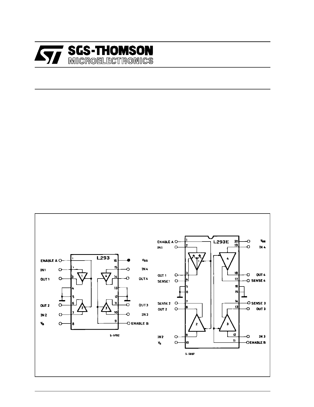
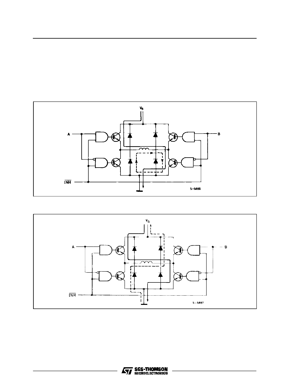
Figure 1 shows the internal structure of the L293,
L293E and L298. The L293 and L293E are repre-
sented as four push pull drivers while the internal
schematic is given for the L298. Though they are
drawn differently the L293E and L298 are identical
in structure ; the L293 differs in that it does not have
external emitter connections.
Figure 1 : The L293, L293E and L298 contain four push pull drivers. Each driver is controlled by a logic input
and each pair (a bridge) is controlled by an enable input. Additionally, the L293E has external emit-
ter connections for each driver and the L298 has emitter connections for each bridge.
1/11
Figure 1 (continued).
The L293 is packaged in a 12 + 4 lead POWERDIP
package (a 16-pin DIP with the four center leads
used to conduct heat to the PC board copper) and
handles 1A per channel (1.5 peak) at voltages up to
36 V.
The L293E, also rated at 1 A/36 V, is mounted in a
16 + 4 lead POWERDIP package. A 15-lead MUL-
TIWATT plastic power package is used for the
L298N which handles up to 2A per channel at vol-
tages to 46 V.
All three devices includes on-chip thermalprotection
and feature high noise immunity. The high switching
speed makes them particularly suitable for switch
mode control.
PARALLELING OUTPUTS
Higher output currents can be obtained by paralle-
ling the outputs of both bridges. For example, the
outputs of an L298N can be connected in parallel to
make a single 3.5 A bridge. To ensure that the cur-
rent is fairly divided between the bridges they must
be connected as shown in figure 2. In other words,
channel one should be paralleled with channel four
and channel two paralleled with channel three.
Apart from this rule the connection is very strai-
ghtforward - the inputs, enables, outputs and emit-
ters are simply connected together.
The outputs of an L293 or L293E can also be paral-
leled - in this case too channel 1 must be paralleled
with channel 4 and channel 2 with channel 3.
But if two bridges are needed this is not a good idea
because an L298N may be used. However, if only
Figure 2 : For higher currents outputs can be paral-
leled. Take care to parallel channel 1
with channel 4 and channel 2 with chan-
nel 3.
APPLICATION NOTE
2/11
one bridge is required an L293 connected as a sin-
gle bridge may be cheaper than an underutilized
L298N.
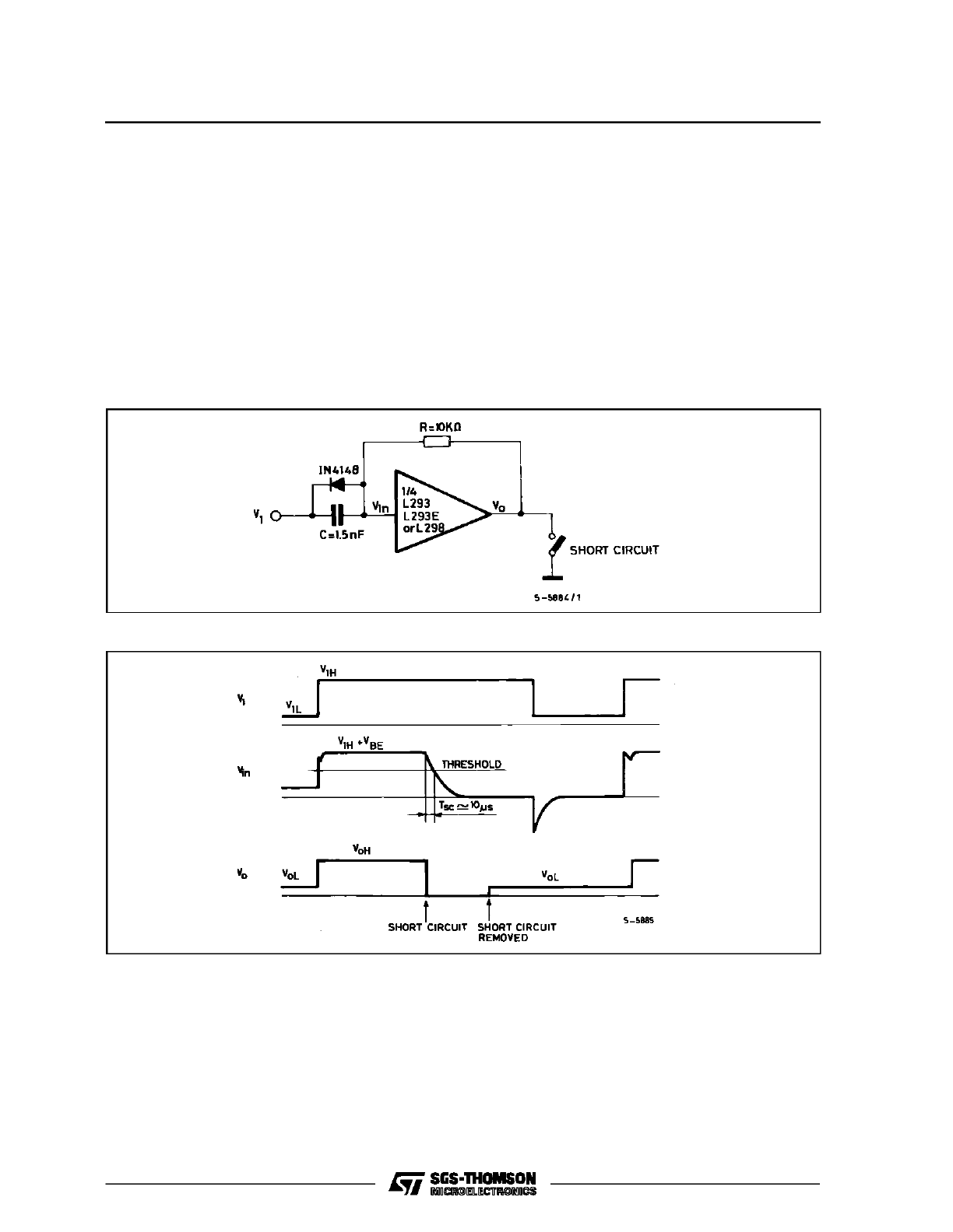
SHORT CIRCUIT PROTECTION
L293 and L298N drivers can be damaged by short
circuits from the output to ground or to the supply.
Short circuits to ground are by far the most common
and can be protected against by the circuit shown
in figure 3.
When the output is short circuited the input is pulled
low after a delay of roughly 10
µ
s, a period determi-
ned by the RC time constant. The upper transistor
of the output stage is thus turned off, interruptingthe
short circuit current. When the short is removed the
circuit recovers automatically. This is shown by the
waveforms of figure 4.
Note that if the short circuit is removed while V1 is
high the output stays low because the capacitor C
is charged to V
IH
. The system is reset by the falling
edge of V1, which discharges C.
Figure 3 : This circuit protects a driver from output short circuits to ground.
Figure 4 : Waveforms illustrating the short circuit protection provided by the circuit of fig. 3.
DC MOTOR DRIVING
In application where rotation is always in the same
sense a single driver (half bridge) can be used to drive
a smallDC motor.The motor may be connectedeither
to supply or to ground as shown in figure 5.
The only difference between these two alternatives
is that the control logic is inverted - a useful fact to
remember when minimising control logic.
Each device can drive four motors connected in this
way. The maximum motor current is 1A for the L293
and 2A for the L298N. However if several motors are
driven continuously care should be taken to avoid
exceeding the maximum power dissipation of the
package.
APPLICATION NOTE
3/11
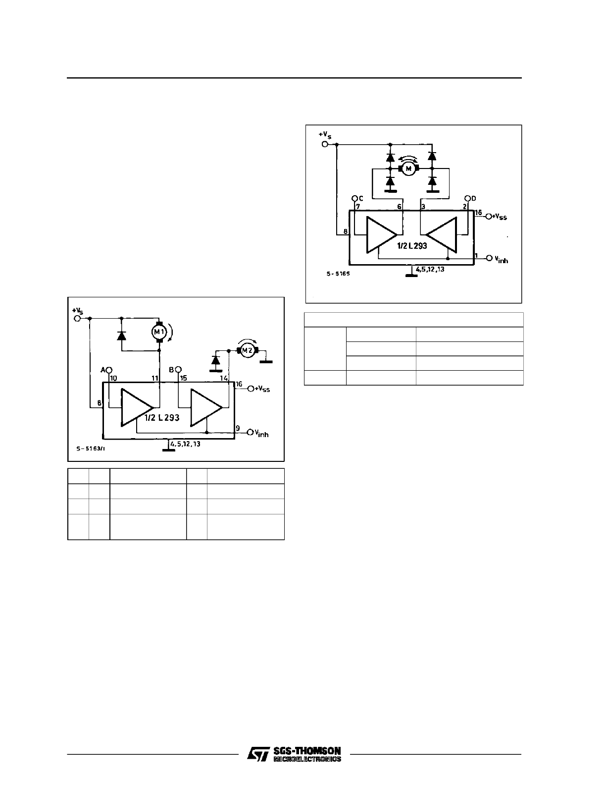
Each motor in this configuration is controlled by its
own logic input which gives two alternatives : run
and fast stop (the motor shorted by one of the tran-
sistors).
The enable/inhibit inputs also allow a free running
motor stop by turning off both transistors of the dri-
ver. Since theseinputs are common to two channels
(one bridge) this featurecan only be used when both
channels are disabled together.
A full bridge configurationis used to drive DC motors
in both directions (figure 6). Using the logic inputs of
the two channels the motor can be made to run
clockwise, run anticlockwise or stop rapidly.
Figure 5 : For rotation in one direction DC motors
are driven by one channel and can be
connected to supply or ground.
V
inh
+A
+M1
+B
+M2
H
H
Fast Motor Stop
H
Run
H
L
Run
L
Fast Motor Stop
L
X
Free Running
Motor Stop
X
Free Running
Motor Stop
L = Low
H = High
X = Don’t Care
Again, the enable/inhibitinput is used for a free run-
ning stop - it turns off all four transistors of the bridge
when low. A very rapid stop may be achieved by re-
versing the current, though this requires more care-
ful design to stop the motor dead. In practice a
tachometer dynamo and closed loop control are
usually necessary. Like the previous circuit, this
configuration is suitable for motors with currents up
to 1A (L293/L293E) or 2A (L298N).
The motor speed in these examples can be control-
led by switching the drivers with pulse width modu-
lated squarewaves. This approach is particularly
suitable for microcomputer control.
For undirectional drive with a single channel the
Figure 6 : A bridge is used for bidirectional drive of
DC motors.
Inputs
V
inh
= H C = H ; D = L
Turn Right
C = L ;
D = H
Turn Left
C = D
Fast Motor Stop
V
inh
= L
C = X ;
D = X
Free Running Motor Stop
L = Low
H = High
X = Don’t Care
PWM control signal can be applied to either the
channel input or the appropriate enable input. In
both cases the recirculation path is through the sup-
pression diode and motor, giving a fairly slow decay.
From a practical point of view it is preferable to con-
trol the channel input because the circuit response
is faster. This is very convenient because each
channel has an independent input.
The situation is different for bidirectional motors dri-
ven by a bridge. In this case the two alternatives
have different effects. If the channel inputs are dri-
ven by the PWM signal, with suitable logic, the re-
circulation path is through a diode, the motor and a
transistor (figure 7a), givind a slow decay. On the
other hand, if the enable input is controlled the re-
circulation path is from groundto supply through two
diodes and the winding. This path gives a faster de-
cay (figure 7b).
Figure 8 shows a practical example of PWM motor
speed control. This circuit includes the oscillator and
modulator and allows independent regulation of the
speeds of the two motors. The channel inputs are
used to control the direction.
An interesting feature of this circuit is that it takes ad-
vantage of the threshold of the enable/inhibit input
to economiseon comparators. The TBA820M audio
amplifier generates triangle waves, the DC level of
APPLICATION NOTE
4/11
which is varied from 0 to 5 V by means of P1 and
P2.
Since the switching threshold of the L293’s ena-
ble/inhibit inputs is roughly 2 V the duty cycle of the
output current (and hence the motor speed) is con-
trolled by the setting of the potentiometer.
In this circuit the switching frequency is set by R1/C1
and the amplitude of the oscillator signal is set by the
divider R2/R3.
Figure 7a : If the current shown by the solid line is interrupted by bringing A low the current recirculates round
the dotted path. Decay is slow.
Figure 7b : If the enable input is brought low to interrupt the current indicated by the solid line the current
recirculates from ground to V
S
and the decay is faster.
APPLICATION NOTE
5/11
Figure 8 : This circuit illustrates PWM control of the motor speed. The speed of each motor is controlled
independently.
STEPPER MOTOR DRIVING
Monolithic bridge drivers are extremely useful for
stepper motor driving because they simplify the use
of bipolar motors. This is an important point since a
bipolar stepper motor costs less than an equivalent
unipolar motor (it has fewer windings) and gives
more torque per unit volume, other things being
equal.
The basic configurationfor bipolarsteppermotor dri-
ving is shown in figure 9. In this example it is assu-
med that a suitable translator (phase sequence
generator) is connected to the four channel inputs.
Either an L293 or an L298N can be used in this cir-
cuit ; an L293E would be wasted compared to an
L293 because load current regulation, and hence
the sense resistor connection, is not used.
But load current requlation is highly desirable to ex-
ploit the performance characteristics of the motor.
Using an L293E or L298N this can be implemented
by adding an LM339 quad comparator as shown in
figure 10.
This is another circuit that requires an external tran-
slator but it providesindependent PWM chopper re-
gulation of the current in each winding.
Looking at motor phaseone, the comparator output
is initially high, enabling the bridge through pin 1.
The current in the motor winding rises until the volt-
age across the sensing resistor R2 produces a volt-
age at the inverting input of the comparator equal to
the voltageon the non-inverting input (370 mV). This
value is produced by the divider R10/R11 and by the
hysteresis determined by R6 and R8.
At this point the comparator switches, disabling the
bridge. The current in the winding recirculates
through D5 and D6 until the voltage across R2 falls
below the lower threshold of the comparator. The
comparator then switches again and the cycle repe-
ats.
APPLICATION NOTE
6/11
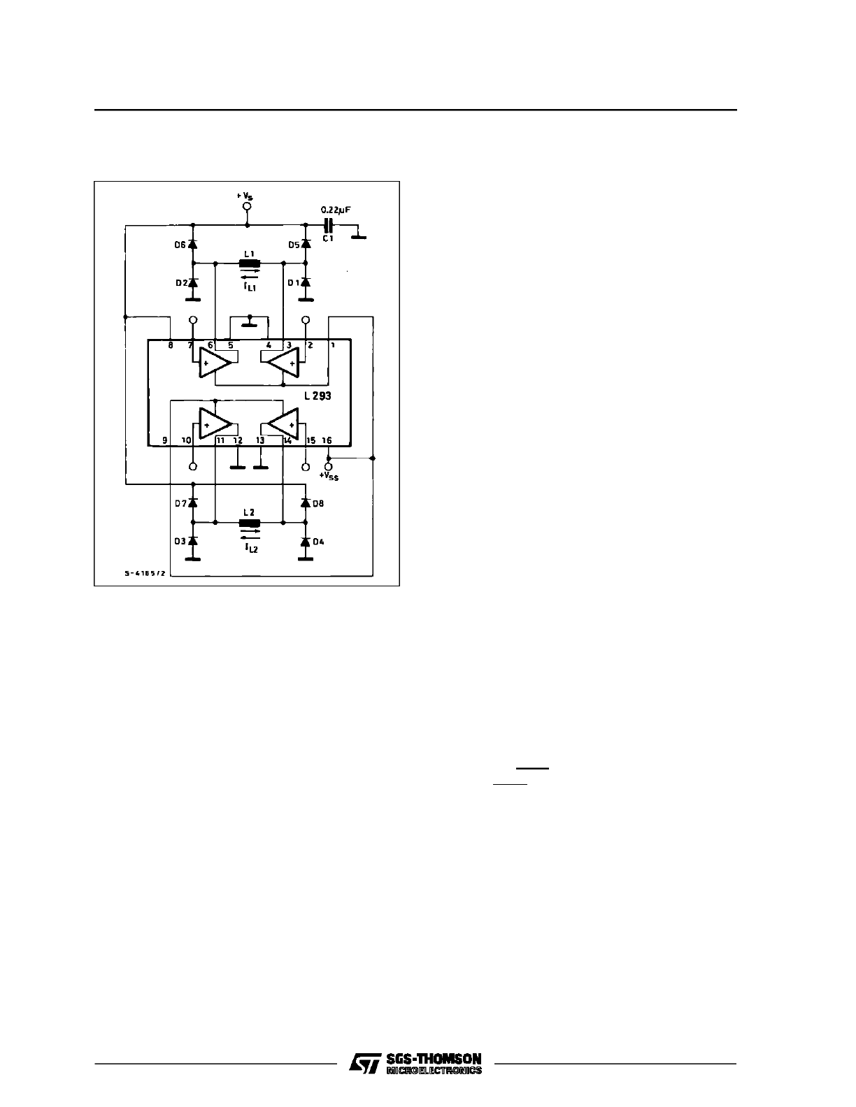
Figure 9 : A single device can be used to drive a two
phase bipolar stepper motor.
The peak current in each winding is determined by
V
ref
(in this case it is 0.5 A) and the switching rate -
and hence the average current - depends on the hy-
steresis of the comparator and R4C4. With the com-
ponent values shown the switching frequency is
roughly 20 kHz.
The figure 10 circuit uses only half of the LM339
quad comparator. With the adition of a few extra
passive components we can take advantage of the
spare comparators to implement short circuit pro-
tection. Figure 11 shows how this is done.
As before, comparators 1 and 2 regulate the current
in the windings but in this case the connection is dif-
ferent because the inhibit/enableinputs are used for
the short circuit protection. The PWM choppers act
on the channel inputs through the four clamp diodes
D9, D10, D11 and D12. This is a simple trick which
allows us to use the channel inputs both for the step
sequencing and the choppers.
Comparators 3 and 4 realize the short circuit protec-
tion function. Again looking at phase one, compara-
tor 3 operates as a flip flop. Its output is connected
to the bridge enable inputs (pins 1 and 11) and is
normally high, enabling the drivers. If the output cur-
rent (sensed by RS1) reaches double the nominal
value the comparator CP3 switches, inhibiting the
two bridges.
The comparator remains in this state until the V
SS
supply (5 V) is interrupted. The outputs of compara-
tors 3 and 4 are ORed togetherso that a short circuit
on one phase disables both bridges.
For this circuit V
A
should be less than 300 mV (V
A
is the voltage on the + input of CP1). From the value
chosen for V
A
and the desired phase current the
sense resistor RS1 (and RS2) is chosen. The cur-
rent ripple should be at least 30 mA to avoid spurious
triggering of CP1 and CP2.
The componentvalues indicated are for a motor with
a resistance of 37
Ω
/phase, inductance of 80
mH/phase and a current of 280 mA/phase. V
ref
is
243 mV giving V
A
= 274 mV when the output is high
and 243 mV when the output is low. Since RS1 = 1
Ω
the current is the winding reaches 274 mA peak and
has a ripple of roughly 30 mA. The switching fre-
quency depends on the hysteresis of the compara-
tors and the motor characteristics. For this example
the frequency is about 15 kHz.
Stepper motor drive circuits can be simplified using
the L297 stepper motor controller which contains a
translator to generate the phase sequences plus a
dual PWM chopper to regulate the phase currents.
The L297 connects directly to the L293E or L298N
as shown in figure 12. This example drives a bipolar
stepper motor with winding currents up to 2.5 A. For
lower currents an L293E is used and more powerful
motors can be driven by two L298N’swith paralleled
bridges, giving up to 3.5 A.
In this configuration the motor is controlled through
the L297. A step clock moves the motor one incre-
ment, the CW/CCW input controls the direction and
the HALF/FULL input selects half step or normal
operation. The input V
ref
is connected to a suitable
voltage reference and sets the peak winding current
in the motor. The choppers in the L297 can operate
on the phase lines or the inhibit lines, depending on
the state of the logic input called CONTROL.
For a more detailed description of the L297 see ”In-
troducing the L297 Stepper Motor Controller”.
APPLICATION NOTE
7/11
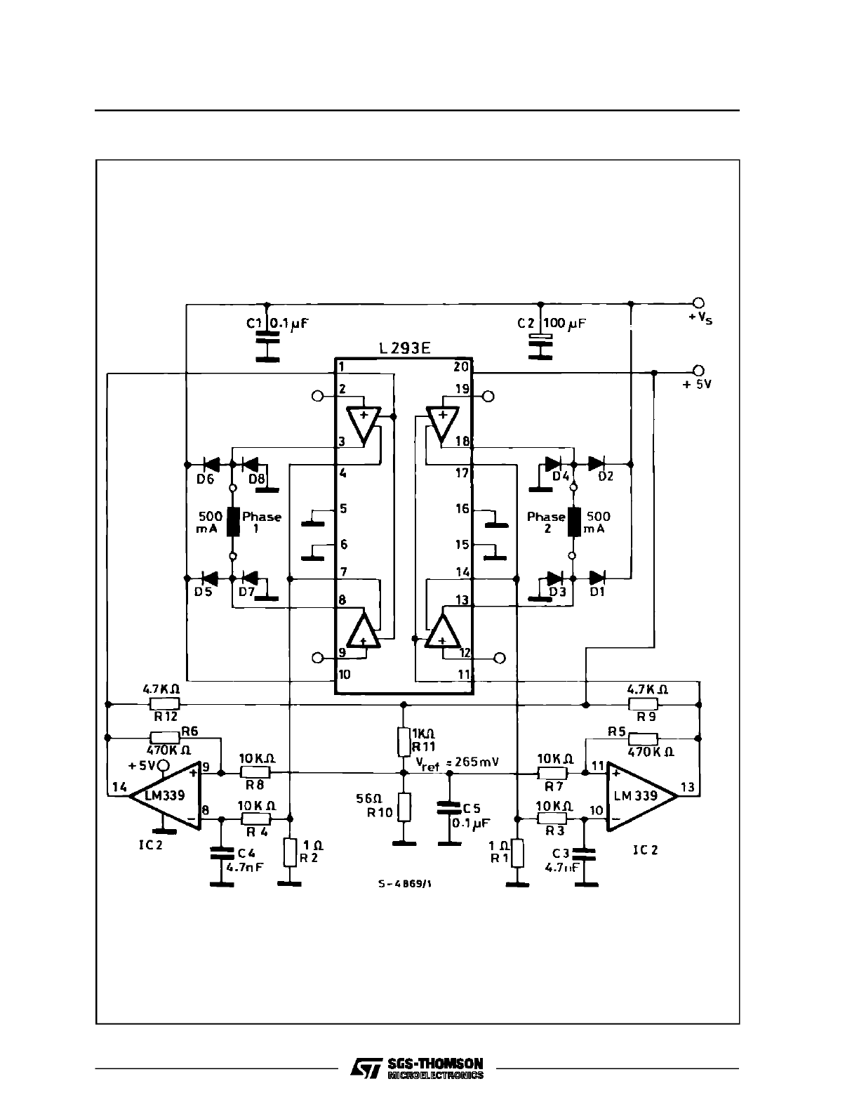
Figure 10 : Two comparators provide chopper current regulation in this bipolar stepper motor drive circuit.
APPLICATION NOTE
8/11
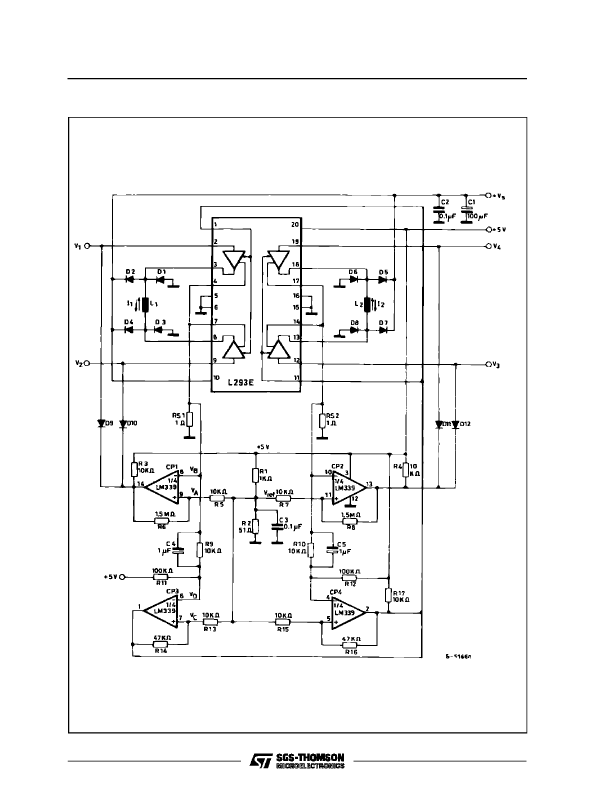
Figure 11 : With a quad comparator both current regulation and short circuit protection can be obtained.
APPLICATION NOTE
9/11
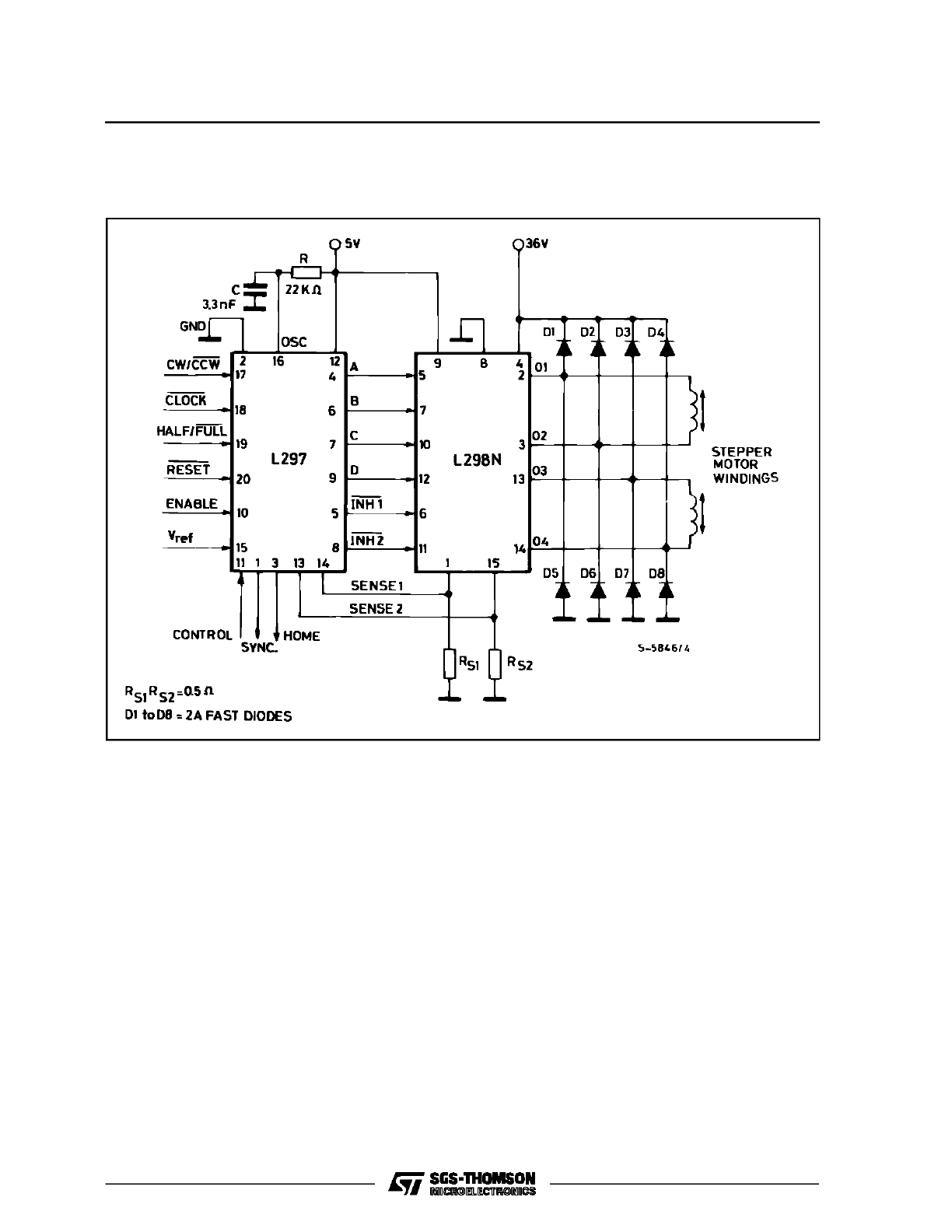
Figure 12 : An L297 stepper motor controller and a L298N driver together from a complete microprocessor-
to-stepper motor interface. This circuit drives bipolar stepper motors with winding currents up to 2
A.
APPLICATION NOTE
10/11

Information furnished is believed to be accurate and reliable. However, SGS-THOMSON Microelectronics assumes no responsibility for the
consequences of use of such information nor for any infringement of patents or other rights of third parties which may result from its use.
No license is granted by implication or otherwise under any patent or patent rights of SGS-THOMSON Microelectronics. Specifications
mentioned in this publication are subject to change without notice. This publication supersedes and replaces all information previously
supplied. SGS-THOMSON Microelectronics products are not authorized for use as critical components in life support devices or systems
without express written approval of SGS-THOMSON Microelectronics.
1995 SGS-THOMSON Microelectronics - All Rights Reserved
SGS-THOMSON Microelectronics GROUP OF COMPANIES
Australia - Brazil - France - Germany - Hong Kong - Italy - Japan - Korea - Malaysia - Malta - Morocco - The Netherlands - Singapore -
Spain - Sweden - Switzerland - Taiwan - Thaliand - United Kingdom - U.S.A.
APPLICATION NOTE
11/11