

SMSC USB5434B
Revision 1.0 (09-06-12)
DATASHEET
Datasheet
PRODUCT FEATURES
General Description
The SMSC USB5434B hub is a 4-port SuperSpeed/Hi-
Speed, low-power, configurable hub controller family
fully compliant with the USB 3.0 Specification. The
USB5434B supports 5 Gbps SuperSpeed (SS),
480 Mbps Hi-Speed (HS), 12 Mbps Full-Speed (FS) and
1.5 Mbps Low-Speed (LS) USB signalling for complete
coverage of all defined USB operating speeds.
The USB5434B supports legacy USB speeds through its
USB 2.0 hub controller. The new SuperSpeed hub
controller operates in parallel with the USB 2.0
controller, so the 5 Gbps SuperSpeed data transfers are
not affected by the slower USB 2.0 traffic.
The USB5434B is configured for operation through
internal default settings.
Features
USB 3.0 compliant 5 Gbps, 480 Mbps, 12 Mbps and
1.5 Mbps operation, USB pins are 5 V tolerant
— Integrated termination and pull-up/pull-down resistors
Four downstream USB 3.0 ports
Optimized for low-power operation and low thermal
dissipation
Single 25 MHz XTAL or clock input for all on-chip PLL
and clocking requirements
Supports JTAG boundary scan
IETF RFC 4122 compliant 128-bit UUID
Software Features
Compatible with Microsoft Windows 7, Vista, XP,
Mac OSX10.4+, and Linux Hub Drivers
USB5434B
4-Port SS/HS USB Hub Controller
Order Numbers:
* Add “TR” to the end of any order number to order tape and reel. Reel size is 3000 pieces.
This product meets the halogen maximum concentration values per IEC61249-2-21
For RoHS compliance and environmental information, please visit
Please contact your SMSC sales representative for additional documentation related to this product
such as application notes, anomaly sheets, and design guidelines.
ORDER NUMBERS
*
DESCRIPTION
LEAD-FREE ROHS
COMPLIANT
PACKAGE
TEMPERATURE
RANGE
USB5434B-JZX
USB 3.0 4-Port Hub
64QFN
9 x 9mm
6.0 mm exposed pad
0ºC to 70ºC
4-Port SS/HS USB Hub Controller
Datasheet
Revision 1.0 (09-06-12)
2
SMSC USB5434B
DATASHEET
Copyright © 2012 SMSC or its subsidiaries. All rights reserved.
Circuit diagrams and other information relating to SMSC products are included as a means of illustrating typical applications. Consequently, complete information sufficient for
construction purposes is not necessarily given. Although the information has been checked and is believed to be accurate, no responsibility is assumed for inaccuracies. SMSC
reserves the right to make changes to specifications and product descriptions at any time without notice. Contact your local SMSC sales office to obtain the latest specifications
before placing your product order. The provision of this information does not convey to the purchaser of the described semiconductor devices any licenses under any patent
rights or other intellectual property rights of SMSC or others. All sales are expressly conditional on your agreement to the terms and conditions of the most recently dated
version of SMSC's standard Terms of Sale Agreement dated before the date of your order (the "Terms of Sale Agreement"). The product may contain design defects or errors
known as anomalies which may cause the product's functions to deviate from published specifications. Anomaly sheets are available upon request. SMSC products are not
designed, intended, authorized or warranted for use in any life support or other application where product failure could cause or contribute to personal injury or severe property
damage. Any and all such uses without prior written approval of an Officer of SMSC and further testing and/or modification will be fully at the risk of the customer. Copies of
this document or other SMSC literature, as well as the Terms of Sale Agreement, may be obtained by visiting SMSC’s website at http://www.smsc.com. SMSC is a registered
trademark of Standard Microsystems Corporation (“SMSC”). Product names and company names are the trademarks of their respective holders.
The Microchip name and logo, and the Microchip logo are registered trademarks of Microchip Technology Incorporated in the U.S.A. and other countries.
SMSC DISCLAIMS AND EXCLUDES ANY AND ALL WARRANTIES, INCLUDING WITHOUT LIMITATION ANY AND ALL IMPLIED WARRANTIES OF MERCHANTABILITY,
FITNESS FOR A PARTICULAR PURPOSE, TITLE, AND AGAINST INFRINGEMENT AND THE LIKE, AND ANY AND ALL WARRANTIES ARISING FROM ANY COURSE
OF DEALING OR USAGE OF TRADE. IN NO EVENT SHALL SMSC BE LIABLE FOR ANY DIRECT, INCIDENTAL, INDIRECT, SPECIAL, PUNITIVE, OR CONSEQUENTIAL
DAMAGES; OR FOR LOST DATA, PROFITS, SAVINGS OR REVENUES OF ANY KIND; REGARDLESS OF THE FORM OF ACTION, WHETHER BASED ON CONTRACT;
TORT; NEGLIGENCE OF SMSC OR OTHERS; STRICT LIABILITY; BREACH OF WARRANTY; OR OTHERWISE; WHETHER OR NOT ANY REMEDY OF BUYER IS HELD
TO HAVE FAILED OF ITS ESSENTIAL PURPOSE, AND WHETHER OR NOT SMSC HAS BEEN ADVISED OF THE POSSIBILITY OF SUCH DAMAGES.

Conventions
Within this manual, the following abbreviations and symbols are used to improve readability.
Example
Description
BIT
Name of a single bit within a field
FIELD.BIT
Name of a single bit (BIT) in FIELD
x…y
Range from x to y, inclusive
BITS[m:n]
Groups of bits from m to n, inclusive
PIN
Pin Name
zzzzb
Binary number (value zzzz)
0xzzz
Hexadecimal number (value zzz)
zzh
Hexadecimal number (value zz)
rsvd
Reserved memory location. Must write 0, read value indeterminate
code
Instruction code, or API function or parameter
Section Name
Section or Document name
x
Don’t care
<Parameter>
<> indicate a Parameter is optional or is only used under some conditions
{,Parameter}
Braces indicate Parameter(s) that repeat one or more times
[Parameter]
Brackets indicate a nested Parameter. This Parameter is not real and actually decodes
into one or more real parameters.
4-Port SS/HS USB Hub Controller
Datasheet
SMSC USB5434B
3
Revision 1.0 (09-06-12)
DATASHEET

4-Port SS/HS USB Hub Controller
Datasheet
Revision 1.0 (09-06-12)
4
SMSC USB5434B
DATASHEET
Table of Contents
Chapter 1 Block Diagram . . . . . . . . . . . . . . . . . . . . . . . . . . . . . . . . . . . . . . . . . . . . . . . . . . . . . 7
Chapter 2 Overview . . . . . . . . . . . . . . . . . . . . . . . . . . . . . . . . . . . . . . . . . . . . . . . . . . . . . . . . . . 8
Chapter 3 Pin Information . . . . . . . . . . . . . . . . . . . . . . . . . . . . . . . . . . . . . . . . . . . . . . . . . . . . 9
3.1
Pin Configurations . . . . . . . . . . . . . . . . . . . . . . . . . . . . . . . . . . . . . . . . . . . . . . . . . . . . . . . . . . . . . . 9
3.2
Pin Descriptions (Grouped by Function). . . . . . . . . . . . . . . . . . . . . . . . . . . . . . . . . . . . . . . . . . . . . 10
3.3
Buffer Type Descriptions . . . . . . . . . . . . . . . . . . . . . . . . . . . . . . . . . . . . . . . . . . . . . . . . . . . . . . . . 13
Chapter 4 DC Parameters. . . . . . . . . . . . . . . . . . . . . . . . . . . . . . . . . . . . . . . . . . . . . . . . . . . . 14
4.1
Maximum Guaranteed Ratings . . . . . . . . . . . . . . . . . . . . . . . . . . . . . . . . . . . . . . . . . . . . . . . . . . . . 14
4.2
Operating Conditions . . . . . . . . . . . . . . . . . . . . . . . . . . . . . . . . . . . . . . . . . . . . . . . . . . . . . . . . . . . 15
4.3
DC Electrical Characteristics . . . . . . . . . . . . . . . . . . . . . . . . . . . . . . . . . . . . . . . . . . . . . . . . . . . . . 16
4.4
Capacitance . . . . . . . . . . . . . . . . . . . . . . . . . . . . . . . . . . . . . . . . . . . . . . . . . . . . . . . . . . . . . . . . . . 17
Chapter 5 AC Specifications . . . . . . . . . . . . . . . . . . . . . . . . . . . . . . . . . . . . . . . . . . . . . . . . . . 18
5.1
Oscillator/Crystal. . . . . . . . . . . . . . . . . . . . . . . . . . . . . . . . . . . . . . . . . . . . . . . . . . . . . . . . . . . . . . . 18
5.2
External Clock. . . . . . . . . . . . . . . . . . . . . . . . . . . . . . . . . . . . . . . . . . . . . . . . . . . . . . . . . . . . . . . . . 19
5.2.1
USB 2.0 . . . . . . . . . . . . . . . . . . . . . . . . . . . . . . . . . . . . . . . . . . . . . . . . . . . . . . . . . . . . . . 19
Chapter 6 Package Drawing . . . . . . . . . . . . . . . . . . . . . . . . . . . . . . . . . . . . . . . . . . . . . . . . . . 20
Chapter 7 Revision History. . . . . . . . . . . . . . . . . . . . . . . . . . . . . . . . . . . . . . . . . . . . . . . . . . . 22
Appendix A (Acronyms) . . . . . . . . . . . . . . . . . . . . . . . . . . . . . . . . . . . . . . . . . . . . . . . . . . . . . . . 23
Appendix B (References) . . . . . . . . . . . . . . . . . . . . . . . . . . . . . . . . . . . . . . . . . . . . . . . . . . . . . . 24

4-Port SS/HS USB Hub Controller
Datasheet
SMSC USB5434B
5
Revision 1.0 (09-06-12)
DATASHEET
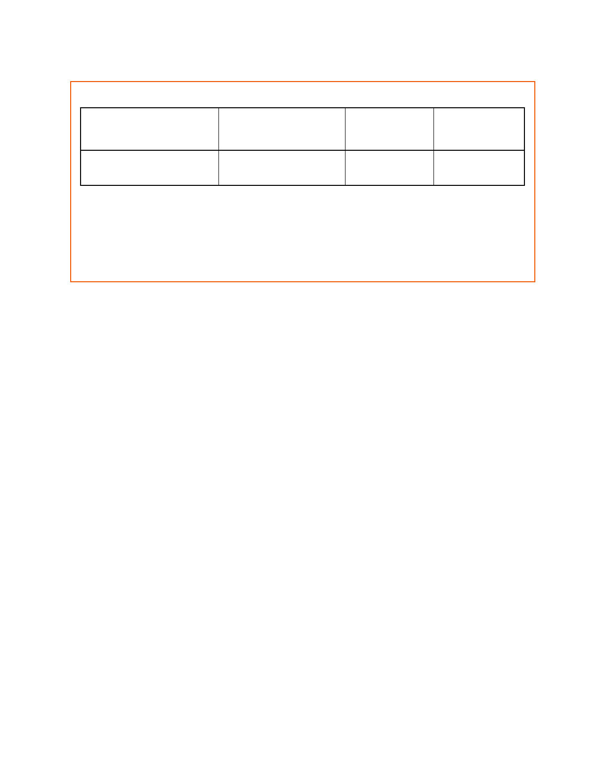
List of Tables
Table 3.1
USB5434B Pin Descriptions . . . . . . . . . . . . . . . . . . . . . . . . . . . . . . . . . . . . . . . . . . . . . . . . . 10
Table 3.2
Buffer Type Descriptions . . . . . . . . . . . . . . . . . . . . . . . . . . . . . . . . . . . . . . . . . . . . . . . . . . . 13
Table 4.1
DC Electrical Characteristics . . . . . . . . . . . . . . . . . . . . . . . . . . . . . . . . . . . . . . . . . . . . . . . . 16
Table 4.2
Pin Capacitance . . . . . . . . . . . . . . . . . . . . . . . . . . . . . . . . . . . . . . . . . . . . . . . . . . . . . . . . . . 17
Table 5.1
Crystal Circuit Legend . . . . . . . . . . . . . . . . . . . . . . . . . . . . . . . . . . . . . . . . . . . . . . . . . . . . . 18
Table 6.1
USB5434B 64-Pin QFN Dimensions . . . . . . . . . . . . . . . . . . . . . . . . . . . . . . . . . . . . . . . . . . 20
Table 7.1
Customer Revision History . . . . . . . . . . . . . . . . . . . . . . . . . . . . . . . . . . . . . . . . . . . . . . . . . . 22

4-Port SS/HS USB Hub Controller
Datasheet
Revision 1.0 (09-06-12)
6
SMSC USB5434B
DATASHEET
List of Figures
Figure 1.1
USB5434B Block Diagram . . . . . . . . . . . . . . . . . . . . . . . . . . . . . . . . . . . . . . . . . . . . . . . . . . . 7
Figure 3.1
USB5434B 64-Pin QFN . . . . . . . . . . . . . . . . . . . . . . . . . . . . . . . . . . . . . . . . . . . . . . . . . . . . . 9
Figure 4.1
Supply Rise Time Model. . . . . . . . . . . . . . . . . . . . . . . . . . . . . . . . . . . . . . . . . . . . . . . . . . . . 15
Figure 5.1
Typical Crystal Circuit . . . . . . . . . . . . . . . . . . . . . . . . . . . . . . . . . . . . . . . . . . . . . . . . . . . . . . 18
Figure 5.2
Formula to Find the Value of C1 and C2 . . . . . . . . . . . . . . . . . . . . . . . . . . . . . . . . . . . . . . . 18
Figure 6.1
USB5434B 64 Pin QFN Package . . . . . . . . . . . . . . . . . . . . . . . . . . . . . . . . . . . . . . . . . . . . . 20
Figure 6.2
Recommended PCB Land Pattern . . . . . . . . . . . . . . . . . . . . . . . . . . . . . . . . . . . . . . . . . . . . 21
4-Port SS/HS USB Hub Controller
Datasheet
SMSC USB5434B
7
Revision 1.0 (09-06-12)
DATASHEET
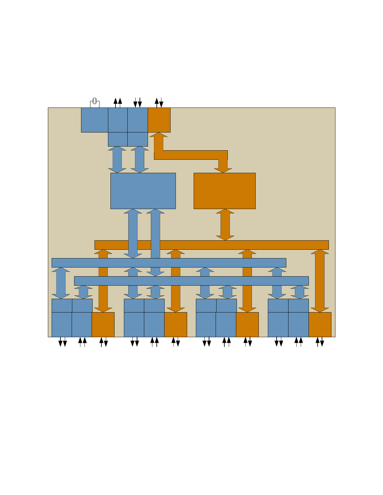
Chapter 1 Block Diagram
Figure 1.1 USB5434B Block Diagram
USB 3.0 Hub Controller
TX
SS
PHY
RX
SS
PHY
USB2.0
PHY
USB 2.0 Hub Controller
HS/FS/LS Routing Logic
Common
Block
& PLL
TX
SS
PHY
RX
SS
PHY
USB2.0
PHY
Buffer
Buffer
TX
SS
PHY
RX
SS
PHY
USB2.0
PHY
Buffer
Buffer
TX
SS
PHY
RX
SS
PHY
USB2.0
PHY
Buffer
Buffer
TX
SS
PHY
RX
SS
PHY
USB2.0
PHY
Buffer
Buffer
Upstream USB Port
Downstream USB Port 1
Downstream USB Port 2
Downstream USB Port 3
Downstream USB Port 4
Downstream RX SS bus
Downstream TX SS bus
Buffer
Buffer

4-Port SS/HS USB Hub Controller
Datasheet
Revision 1.0 (09-06-12)
8
SMSC USB5434B
DATASHEET
Chapter 2 Overview
The SMSC USB5434B hub is a 4-port, low-power Hub Controller fully compliant with the USB 3.0 Specification
[2]
.
The USB5434B supports 5 Gbps SuperSpeed (SS), 480 Mbps Hi-Speed (HS), 12 Mbps Full-Speed (FS) and
1.5 Mbps Low-Speed (LS) USB signalling for complete coverage of all defined USB operating speeds.
All required resistors on the USB ports are integrated into the hub. This includes all series termination resistors and
all required pull-down and pull-up resistors on D+ and D- pins. The over-current sense inputs for the downstream
facing ports have internal pull-up resistors.
The USB5434B includes MultiTRAK
TM
technology, which implements a dedicated Transaction Translator (TT) for
each port. Dedicated TTs help maintain consistent full-speed data throughput regardless of the number of active
downstream connections.
The hub controller provides a default configuration, expediting implementation.
4-Port SS/HS USB Hub Controller
Datasheet
SMSC USB5434B
9
Revision 1.0 (09-06-12)
DATASHEET
Chapter 3 Pin Information
This chapter outlines the pinning configurations for each chip. The detailed pin descriptions are listed by function in
Section 3.2: Pin Descriptions (Grouped by Function) on page 10
.
3.1
Pin Configurations
Figure 3.1 USB5434B 64-Pin QFN
Ground Pad
(must be connected to VSS with a via field)
SMSC
USB5434B
(Top View QFN-64)
VD
D3
3
64
US
B2DM
_D
N
2
63
U
SB2
DP_
D
N
2
62
US
B
3D
M
_RXD
N2
61
U
S
B
3D
P
_RXD
N2
60
VD
D1
2
59
USB
3DM_
T
X
D
N
2
58
US
B3
DP
_T
XD
N2
57
US
B2DM
_D
N
1
56
US
B
3D
M
_RXD
N1
54
U
S
B
3D
P
_RXD
N1
53
VD
D1
2
52
USB
3DM_
T
X
D
N
1
51
US
B3
DP
_T
XD
N1
50
VD
D1
2
49
U
SB2
DP_
D
N
1
55
OC
S
1
16
NC
15
14
13
12
11
10
9
8
6
5
4
3
2
1
7
PR
T_CT
L2
32
PR
T_CT
L1
31
TC
FG6
30
TC
FG1
28
TC
FG2
27
TC
FG3
26
TC
FG4
25
VDD12
24
TC
FG5
23
22
21
OC
S
3
20
OC
S
4
19
OC
S
2
18
VDD
33
17
VDD33
48
RBIAS
47
XTALIN/CLK_IN
46
XTALOUT
45
USB3DM_RXUP
44
USB3DP_RXUP
43
VDD12
42
USB3DM_TXUP
41
USB3DP_TXUP
40
USB2DM_UP
39
USB2DP_UP
38
VDD33
37
VB
US
36
ATEST
35
RESET_N
34
TEST
33
PR
T_CT
L3
VDD12
29
USB2DM_DN4
USB2DP_DN4
USB3DM_RXDN4
USB3DP_RXDN4
VDD12
USB3DM_TXDN4
USB3DP_TXDN4
USB2DP_DN3
USB3DM_RXDN3
USB3DP_RXDN3
VDD12
USB3DM_TXDN3
USB3DP_TXDN3
USB2DM_DN3
PRT_CTL4
Indicates pins on the bottom of the device.

4-Port SS/HS USB Hub Controller
Datasheet
Revision 1.0 (09-06-12)
10
SMSC USB5434B
DATASHEET
3.2
Pin Descriptions (Grouped by Function)
An N at the end of a signal name indicates that the active (asserted) state occurs when the signal is at a low voltage
level. When the N is not present, the signal is asserted when it is at a high voltage level. The terms assertion and
negation are used exclusively in order to avoid confusion when working with a mixture of active low and active high
signals. The term assert, or assertion, indicates that a signal is active, independent of whether that level is
represented by a high or low voltage. The term negate, or negation, indicates that a signal is inactive.
Table 3.1 USB5434B Pin Descriptions
SYMBOL
BUFFER
TYPE
DESCRIPTION
USB 3.0 INTERFACE
USB3DP_TXUP
IO-U
USB 3 Upstream
Upstream SuperSpeed transmit data plus
USB3DM_TXUP
IO-U
USB 3 Upstream
Upstream SuperSpeed transmit data minus
USB3DP_RXUP
IO-U
USB 3 Upstream
Upstream SuperSpeed receive data plus
USB3DM_RXUP
IO-U
USB 3 Upstream
Upstream SuperSpeed receive data minus
USB3DP_TXDN[4:1]
IO-U
USB 3 Downstream
Downstream SuperSpeed transmit data plus for ports 1 through 4.
USB3DM_TXDN[4:1]
IO-U
USB 3 Downstream
Downstream SuperSpeed transmit data minus for ports 1 through 4.
USB3DP_RXDN[4:1]
IO-U
USB 3 Downstream
Downstream SuperSpeed receive data plus for ports 1 through 4.
USB3DM_RXDN[4:1]
IO-U
USB 3 Downstream
Downstream SuperSpeed receive data minus for ports 1 through 4.
USB 2.0 INTERFACE
USB2DP_UP
IO-U
USB Bus Data
These pins connect to the upstream USB bus data signals.
USB2DM_UP
IO-U
USB Bus Data
These pins connect to the upstream USB bus data signals.
USB2DP_DN[4:1]
IO-U
USB Downstream
Downstream Hi-Speed data plus for ports 1 through 4.
USB2DM_DN[4:1]
IO-U
USB Downstream
Downstream Hi-Speed data minus for ports 1 through 4.