

2013 - 2016 Microchip Technology Inc.
DS00001588B-page 1
Highlights
• USB 2.0 Compatible 4-Port Hub with two
upstream host port connections
- Provides electronic reconfiguration and re-
assignment of any of its 4 downstream ports
to either of two upstream host ports (“on-the-
fly”)
- Allows multiple USB hosts to share peripher-
als and enables a user to dynamically assign
host ownership
- Embedded Mode - 8 (predefined, OEM
programmable) configurations for port assignment
are selectable via three external control signals
- Peripheral Mode - Dedicated select pin for every
downstream port (total of 4), selectable edge or level
triggered in order to support a wide range of possible
switch configurations and styles
- Each host has a dedicated Single Transac-
tion Translator (Single-TT) for supporting FS/
LS devices, or can also operate in Multi-TT
mode where each downstream port has a
dedicated Transaction Translator.
• Downstream ports can be disabled or defined as
non-removable
• Switching hub can be configured as compound
device for support of ‘embedded’ USB peripherals
• Multiple LED modes for maximum implementation
flexibility
- USB Mode - 2 Single-color LEDs for each
downstream port (total of 8 LEDs)
- Host Ownership Mode - 8 Single-Color LEDs
indicate which upstream host each of the
downstream ports are assigned to.
- Host Ownership & Port Speed Mode - 8 Dual-
Color LEDs are used to indicate which
upstream host each of the downstream ports
are assigned to, while simultaneously indicat-
ing downstream port connection speed.
• Enhanced configuration options available through
either a Single Serial I
2
C EEPROM, or SMBus
Slave Port
- VID/PID/DID
- Port Configuration
- String Descriptors (each can support a maxi-
mum length of 31 characters)
- Custom Manufacturer String
- Custom Product String
- Custom Serial String
- Assignment of downstream ports to upstream
hosts
- Switching mechanism selection
• Hardware Strapping options allow for configura-
tion without an external EEPROM or SMBus Host
- Default VID/PID/DID, allows functionality
when configuration EEPROM is absent
• Complete USB Specification 2.0 Compatibility
- Includes USB 2.0 Hi-Speed Transceivers
- High-Speed (480Mbits/s), Full-Speed
(12Mbits/s) and Low-Speed (1.5Mbits/s)
compatible
- Full power management with choice of Indi-
vidual or Ganged power control
• On-Board 24MHz Crystal Driver Circuit or 24 MHz
external clock driver
• Internal PLL for 480MHz USB 2.0 Sampling
• Internal 1.8V Linear Voltage Regulator
• Integrated USB termination and Pull-up/Pull-down
resistors
• Internal Short Circuit protection of USB differential
signal pins
• 1.8 Volt Low Power Core Operation
• 3.3 Volt I/O with 5V Input Tolerance
• 56-Pin QFN RoHS Compliant Package
USB2524
USB MultiSwitch Hub

USB2524
DS00001588B-page 2
2013 - 2016 Microchip Technology Inc.
TO OUR VALUED CUSTOMERS
It is our intention to provide our valued customers with the best documentation possible to ensure successful use of your Microchip
products. To this end, we will continue to improve our publications to better suit your needs. Our publications will be refined and
enhanced as new volumes and updates are introduced.
If you have any questions or comments regarding this publication, please contact the Marketing Communications Department via
E-mail at
docerrors@microchip.com
. We welcome your feedback.
Most Current Data Sheet
To obtain the most up-to-date version of this data sheet, please register at our Worldwide Web site at:
http://www.microchip.com
You can determine the version of a data sheet by examining its literature number found on the bottom outside corner of any page.
The last character of the literature number is the version number, (e.g., DS30000000A is version A of document DS30000000).
Errata
An errata sheet, describing minor operational differences from the data sheet and recommended workarounds, may exist for cur-
rent devices. As device/documentation issues become known to us, we will publish an errata sheet. The errata will specify the
revision of silicon and revision of document to which it applies.
To determine if an errata sheet exists for a particular device, please check with one of the following:
• Microchip’s Worldwide Web site;
http://www.microchip.com
• Your local Microchip sales office (see last page)
When contacting a sales office, please specify which device, revision of silicon and data sheet (include -literature number) you are
using.
Customer Notification System
Register on our web site at
www.microchip.com
to receive the most current information on all of our products.

2013 - 2016 Microchip Technology Inc.
DS00001588B-page 3
USB2524
Table of Contents
1.0 General Description ........................................................................................................................................................................ 4
2.0 Pin Layout ....................................................................................................................................................................................... 6
3.0 Pin Configuration ............................................................................................................................................................................ 7
4.0 Switching Hub Pin Descriptions ...................................................................................................................................................... 8
5.0 Switching Hub Block Diagram ....................................................................................................................................................... 13
6.0 Assigning Ports ............................................................................................................................................................................. 14
7.0 Configuration Options ................................................................................................................................................................... 16
8.0 LED Interface Description ............................................................................................................................................................. 40
9.0 Reset ............................................................................................................................................................................................. 43
10.0 XNOR Test .................................................................................................................................................................................. 47
11.0 DC Parameters ........................................................................................................................................................................... 48
12.0 AC Specifications ........................................................................................................................................................................ 51
13.0 Package Outline .......................................................................................................................................................................... 52
Appendix A: Data Sheet Revision History ........................................................................................................................................... 54
The Microchip Web Site ...................................................................................................................................................................... 55
Customer Change Notification Service ............................................................................................................................................... 55
Customer Support ............................................................................................................................................................................... 55
Product Identification System ............................................................................................................................................................. 56

USB2524
DS00001588B-page 4
2013 - 2016 Microchip Technology Inc.
1.0
GENERAL DESCRIPTION
The Microchip 4-Port USB 2.0 Switching Hub Controller acts as two independently controllable USB 2.0 Hubs in a single
package with the ability to electronically reassign and reconfigure any of its 4 downstream ports to either of its two
upstream USB ports. This allows two USB hosts to share peripherals and to dynamically reconfigure them.
Any configuration of the downstream ports is possible except simultaneous connection to both upstream ports. Up to 8
different configurations can be selected by a dedicated 3-pin interface, or the 4-pin interface can be used to directly
assign each port to either of the upstream hosts. An external serial EEPROM (or SMBus Host) is used to store the 8
different configuration parameters. However, 8 predefined configurations, as well as generic VID/PID/DID information,
are provided as defaults if no external Serial EEPROM is detected at power up. The SMBus interface can be used to
configure the hub as well as dynamically re-assigning downstream ports to upstream hosts. The SMBus interface can
be “live” while the hub is operational, and allows an external SMBus host to have full access to re-assign ports on an
as-needed basis.
The Microchip 4-Port Switching Hub is fully compliant with the USB 2.0 Specification and will attach to either or both
upstream USB hosts as a Full-Speed Hub or as a Full-/High-Speed Hub. The 4 downstream Hub ports support Low-
Speed, Full-Speed, and High-Speed (if operating as a High-Speed Hub) downstream devices on all of the enabled
downstream ports.
A USB peripheral or USB Hub that is attached to one of the downstream USB2524 ports will be available to one or the
other of the upstream USB host controllers, but can never be simultaneously shared with both host controllers. The user
can switch a peripheral from one host to the other (on-the-fly), and the peripheral will automatically detach from one host
and attach to the other host. Each host will only configure and control the downstream ports that are assigned to it,
including full USB power management and suspend/resume operations.
The USB2524 works with an external USB power distribution switch device to control V
BUS
switching to downstream
ports, and to limit current and sense over-current conditions.
All required resistors on the USB ports are integrated into the Hub. This includes all series termination resistors on D+
and D– pins and all required pull-down and pull-up resistors on D+ and D– pins. The over-current sense inputs for the
downstream facing ports have internal pull-up resistors.
Throughout this document the upstream facing port of the hub will be referred to as the upstream port, and the down-
stream facing ports will be called the downstream ports.
For performance reasons, the Hub provides 1 Transaction Translator (TT) per port (defined as Multi-TT configuration),
and each TT has 1512 bytes of periodic buffer space and 272 Bytes of non- periodic buffer space (divided into 4 non-
periodic buffers per TT), for a total of 1784 bytes of buffer space for each Transaction Translator.
When configured as a Single-TT Hub (required by USB 2.0 Specification), the Single Transaction Translator will have
1512 bytes of periodic buffer space and 272 bytes of non-periodic buffer space (divided into 4 non-periodic buffers per
TT), for a total of 1784 bytes of buffer space for the entire Transaction Translator.
1.1
OEM Selectable Features
A default configuration is available in the USB2524 following a reset. This configuration may be sufficient for some appli-
cations. Strapping option pins make it possible to modify a limited sub-set of the configuration options.
The USB2524 may also be configured by an external EEPROM or a microcontroller. When using the microcontroller
interface, the Hub appears as an SMBus slave device. If the Hub is pin-strapped for external EEPROM configuration
but no external EEPROM is present, then a value of ‘0’ will be written to all configuration data bit fields (the hub will
attach to the host with all ‘0’ values).
The USB2524 supports several OEM selectable features:
• Optional OEM configuration via I
2
C EEPROM or via the industry standard SMBus interface from an external
SMBus Host or Microcontroller.
• Compound device support (port is permanently hardwired to a downstream USB peripheral device).
• Hardware strapping options enable configuration of the following features (when not configured via an EEPROM
or SMBus host).
- Non-Removable Ports
- Port Power Polarity (active high or active low logic)
• Selection of Single (STT) or Multi-Transaction Translator (MTT) capability.
• Selection of Over-Current sensing and Port power control on a individual (port-by-port) or ganged (all ports
together) to match the OEM’s choice of circuit board component selection.

2013 - 2016 Microchip Technology Inc.
DS00001588B-page 5
USB2524
• Selection of end-user method of switching ports between hosts
- Embedded Mode: 8 default configurations that are controlled by OEM programmable registers (or Internal
default settings).
- Peripheral Mode: Each wire directly controls one of the 4 downstream ports. The interface is selectable
between edge triggered operation or level triggered operation for compatibility with many different mechanical
switch configurations or direct control from an external Microcontroller’s GPIO pins.
• Enablement of String Descriptor Support, along with the capability to customize each of the 3 different string
descriptors (up to a maximum size of 31 characters each)
• Selection of LED Mode: USB Mode, Host Ownership Mode, or Host Ownership Mode with Speed Indication.

USB2524
DS00001588B-page 6
2013 - 2016 Microchip Technology Inc.
2.0
PIN LAYOUT
TABLE 2-1:
USB2524 56-PIN QFN PIN CONFIGURATION TABLE
Upstream USB 2.0 Interfaces (6 Pins)
USBUP_DP1
USBUP_DM1
USBUP_DP2
USBUP_DM2
VBUS_DET1
VBUS_DET2
DOWNSTREAM 4-PORT USB 2.0 INTERFACE (30 PINS)
USBDN_DP1
USBDN_DM1
USBDN_DP2
OCS1_N
USBDN_DP3
USBDN_DM3
USBDN_DM2
OCS2_N
LED_A1_N/NON_REM0
LED_A2_N/NON_REM1
LED_A3_N/PRT_DIS0
OCS3_N
LED_B1_N
LED_B2_N
LED_B3_N
PRT_ASSIGN0
PRTPWR1
PRTPWR2
PRT_ASSIGN1
PRTPWR_POL
PRTPWR3
RBIAS
PRT_ASSIGN2
LED_A4_N/PRT_DIS1
USBDN_DM4
USBDN_DP4
PRTPWR4
PRT_ASSIGN3
LED_B4_N
OCS4_N
SERIAL PORT INTERFACE (4 PINS)
SDA/SMBDATA
SCL/SMBCLK/
CFG_SEL0
CFG_SEL1
CFG_SEL2
MISC (5 PINS)
XTAL1/CLKIN
XTAL2
RESET_N
SELF_PWR
TEST
ANALOG POWER & GROUND (5 PINS)
VDDPLL18(1)
VDDA33(4)
DIGITAL POWER, GROUND & NO CONNECT (6 PINS)
VDD33(3)
VDDCR18(2)
NC
TOTAL (56 PINS)
2013 - 2016 Microchip Technology Inc.
DS00001588B-page 7
USB2524
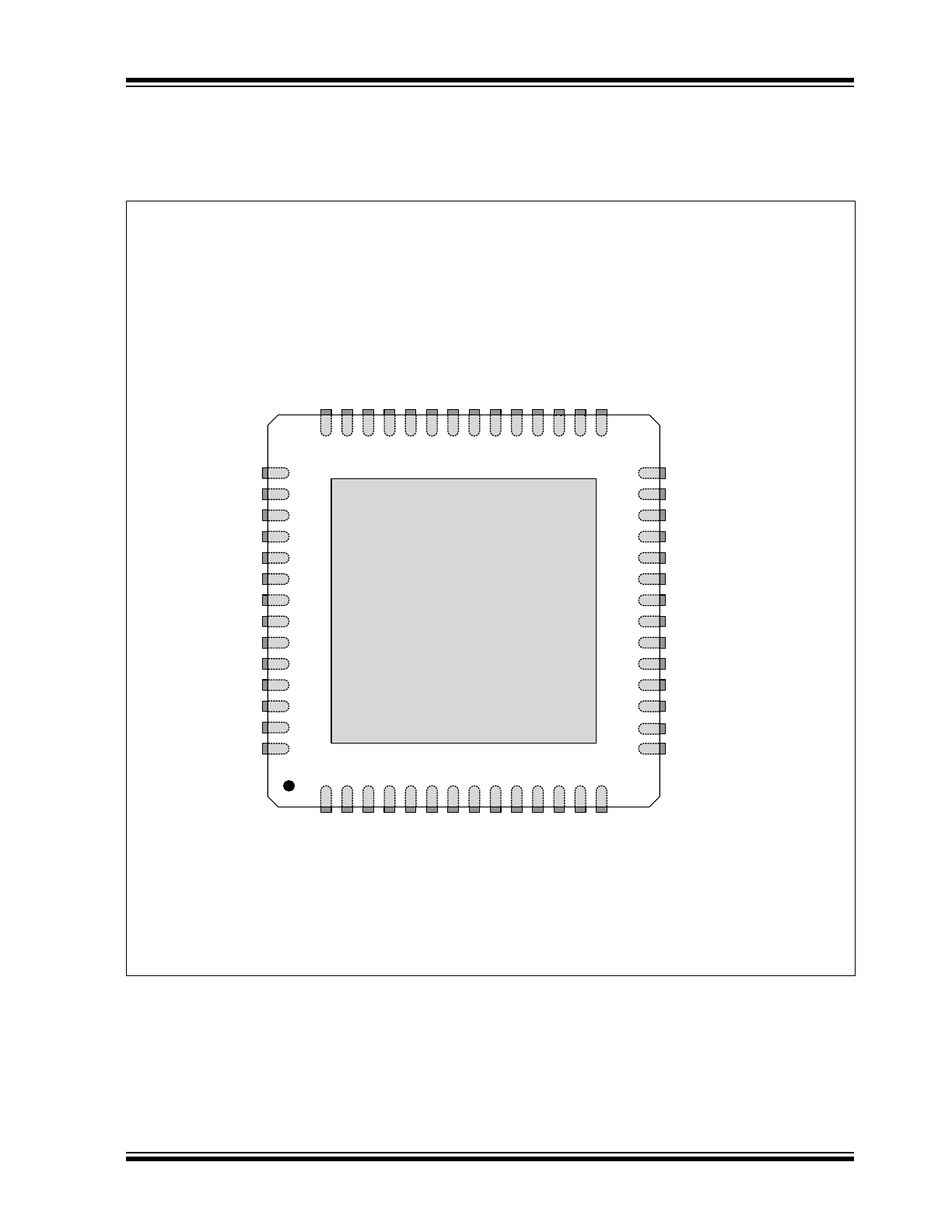
3.0
PIN CONFIGURATION
FIGURE 3-1:
USB2524 QFN-56
thermal slug connects to VSS
41
PRT
_AS
SI
GN
0
40
PRT
_AS
SI
GN
1
39
PRT
_AS
SI
GN
2
38
PRT
_AS
SI
GN
3
37
VDD3
3
36
SE
LF_PWR
35
CF
G_SE
L2
34
CF
G_SE
L1
32
SDA
/SMB
DATA
31
LED_B1
_N
29
LED_B2
_N
30
LED_A1
_N/
NON_RE
M0
33
SC
L/
SM
BC
LK/C
FG_S
EL0
42
LED_A4
_N/
PRT
_DIS
1
26
OCS1_N
25
OCS2_N
24
PRTPWR2
23
PRTPWR3
22
OCS3_N
21
OCS4_N
20
PRTPWR4
19
PRTPWR_POL
18
TEST
17
VDD33
16
VDDCR18
15
LED_B3_N
27
PRTPWR1
28
LED_A2_N/NON_REM1
VDD
A33
1
US
BU
P
_D
P
1
2
USBUP_DM1
3
USB
DN_
DM1
4
USB
DN_
DP1
5
VDD
A33
6
USB
DN_
DP2
7
USB
DN_
DM2
8
USB
DN_
DM3
9
USB
DN_
DP3
10
VDD
A33
11
USB
DN_
DP4
12
USB
DN_
DM4
13
LE
D
_A3_N
/PR
T_
DIS
0
14
RESET_N
44
VBUS_DET1
45
VBUS_DET2
46
VDDA33
47
USBUP_DP2
48
USBUP_DM2
49
XTAL2
51
XTAL1/CLKIN
52
VDDPLL18
53
RBIAS
56
NC
55
LED_B4_N
43
VDD33
54
VDDCR18
50
86%
7RS9LHZ4)1
USB2524
DS00001588B-page 8
2013 - 2016 Microchip Technology Inc.
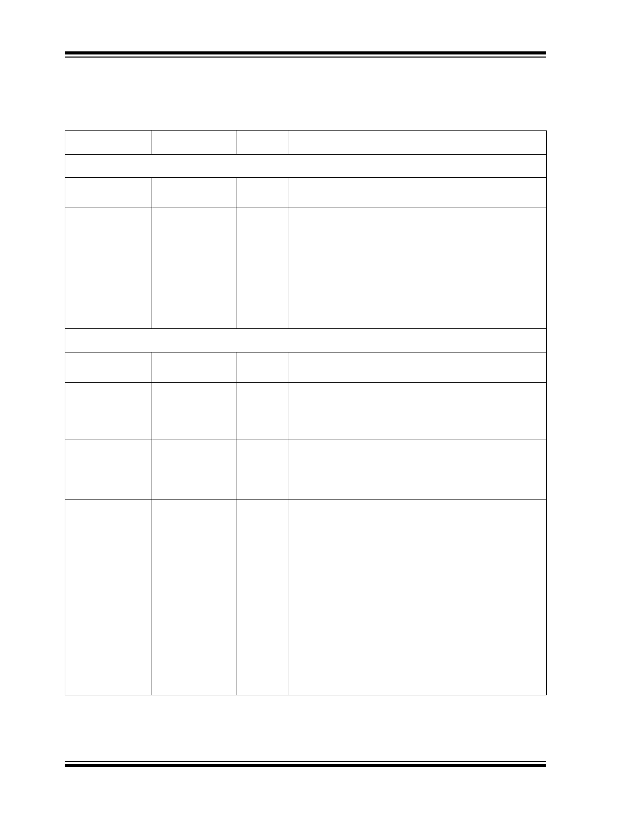
4.0
SWITCHING HUB PIN DESCRIPTIONS
TABLE 4-1:
SWITCHING HUB PIN DESCRIPTIONS
Name
Symbol
Type
Function
UPSTREAM USB 2.0 INTERFACE
USB Bus Data
USBUP_DP[2:1]
USBUP_DM[2:1]
IO-U
These pins connect to the upstream USB bus data signals.
Detect Upstream
VBUS Power
VBUS_DET[2:1]
I/O
Detects state of Upstream VBUS power. The Microchip Hub
monitors VBUS_DET to determine when to assert the
internal D+ pull-up resistor (signaling a connect event).
When designing a detachable hub, this pin must be
connected to the VBUS power pin of the USB port that is
upstream of the hub. (Use of a weak pull-down resistor is
recommended.)
For self-powered applications with a permanently attached
host, this pin must be pulled-up to either 3.3V or 5.0V
(typically VDD33).
4-PORT USB 2.0 HUB INTERFACE
High-Speed USB
Data
USBDN_DP[4:1]
USBDN_DM[4:1]
IO-U
These pins connect to the downstream USB peripheral
devices attached to the Hub’s ports.
USB Power
Enable
PRTPWR[4:1]
O
Enables power to USB peripheral devices (downstream).
The active signal level of the PRTPWR[4] pin is determined
by the Power Polarity Strapping function of the
PRTPWR_POL pin.
Port 4:3 Green
LED
&
Port Disable
strapping option 0
LED_A[4:3]_N/
PRT_DIS[1:0]
I/O12
Green indicator LED for ports 4 and 3. Will be active low
when LED support is enabled via EEPROM or SMBus. See
PRT_DIS1 function description if the hub is configured by
the internal default configuration.
Port Disable
strapping option 1
PRT_DIS1
I/O12
If the hub is configured by the internal default configuration,
PRT_DIS[1:0] will be sampled at RESET_N negation to
determine if ports [4:2] will be permanently disabled. Also,
the active state of LED_A3_N will be determined as follows:
PRT_DIS[1:0] = '00', All ports are enabled,
LED_A4_N is active high,
LED_A3_N is active high.
PRT_DIS[1:0] = '01', Port 4 is disabled,
LED_A4_N is active high,
LED_A3_N is active low.
PRT_DIS[1:0] = '10', Ports 4 & 3 are disabled,
LED_A4_N is active low,
LED_A3_N is active high.
PRT_DIS[1:0] = '11', Ports 4, 3 & 2 are disabled,
LED_A4_N is active low,
LED_A3_N is active low.

2013 - 2016 Microchip Technology Inc.
DS00001588B-page 9
USB2524
Port [2:1] Green
LED
&
Port Non-
Removable
strapping option
LED_A[2:1]_N/
NON_REM[1:0]
I/O12
Green indicator LED for ports 2 and 1. Will be active low
when LED support is enabled via EEPROM or SMBus.
If the hub is configured by the internal default configuration,
these pins will be sampled at RESET_N negation to
determine if ports [3:1] contain permanently attached (non-
removable) devices. Also, the active state of the LED's will
be determined as follows:
NON_REM[1:0] = '00', All ports are removable,
LED_A2_N is active high,
LED_A1_N is active high.
NON_REM[1:0] = '01', Port 1 is non-removable,
LED_A2_N is active high,
LED_A1_N is active low.
NON_REM[1:0] = '10', Ports 1 & 2 are non-removable,
LED_A2_N is active low,
LED_A1_N is active high.
NON_REM[1:0] = '11', Ports 1, 2, & 3 are non-removable,
LED_A2_N is active low,
LED_A1_N is active low.
Enhanced Port
LED Indicators
LED_B[4:1]_N
I/O12
These 4 pins in conjunction with the LED_A[4:1]_N pins
provides a total of 8 LED pins which are used to indicate
upstream host ownership of the downstream ports.
2 operational modes are available
Single Color LED Mode: LED will light to show which host
owns each of the downstream ports. If a port is
“unassigned” then neither LED for that port will light up.
Dual Color LED’s: (note; 4 possible states are displayed to
the user, Green, Red, Orange and Off).
Port Power
Polarity strapping
PRTPWR_POL
I/O
Port Power Polarity strapping determination for the active
signal polarity of the PRTPWR[4:1] pins.
While RESET_N is asserted, the logic state of this pin will
(through the use of internal combinatorial logic) determine
the active state of the PRTPWR[4:1] pins in order to ensure
that downstream port power is not inadvertently enabled to
inactive ports during a hardware reset.
When RESET_N is negated, the logic value will be latched
internally, and will retain the active signal polarity for the
PRTPWR[4:1] pins.
‘1’ = PRTPWR[4:1] pins have active ‘high’ polarity
‘0’ = PRTPWR[4:1] pins have active ‘low’ polarity
Warning: Active Low port power controllers may glitch
the downstream port power when system power is first
applied. Care should be taken when designing with
active low components!
Over Current
Sense
OCS[4:1]_N
IPU
Input from external current monitor indicating an over-
current condition. {Note: Contains internal pull-up to 3.3V
supply}
USB Transceiver
Bias
RBIAS
I-R
A 12.0k
(resistor is attached from ground to this
pin to set the transceiver’s internal bias settings.
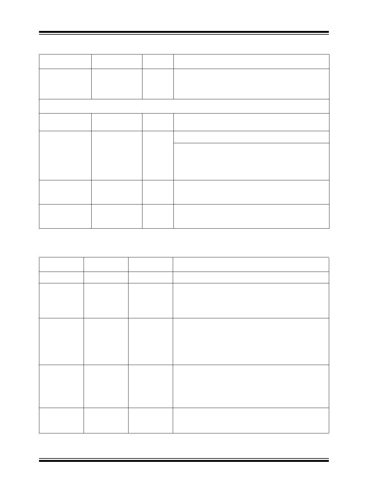
TABLE 4-1:
SWITCHING HUB PIN DESCRIPTIONS (CONTINUED)
Name
Symbol
Type
Function
USB2524
DS00001588B-page 10
2013 - 2016 Microchip Technology Inc.
Assign
Downstream
Ports to Upstream
Host Ports
PRT_ASSIGN
[3:0]
I
Port Assign Interface: Operates in either Embedded mode,
or Peripheral mode. See
Section 6.0, "Assigning Ports"
for
additional details.
SERIAL PORT INTERFACE
Serial Data/SMB
Data
SDA/SMBDATA
IOSD12
(Serial Data)/(SMB Data) signal.
Serial Clock/SMB
Clock
&
Configuration
Programming
Select
SCL/SMBCLK/
CFG_SEL0
IOSD12
(Serial Clock)/(SMB Clock) signal.
CFG_SEL0: The logic state of this multifunction pin is
internally latched on the rising edge of RESET_N
(RESET_N negation), and will determine the hub
configuration method as described in
Table 4-2
.
Configuration
Programming
Select
CFG_SEL1
I
The logic state of this pin is internally latched on the rising
edge of RESET_N (RESET_N negation), and will determine
the hub configuration method as described in
Table 4-2
.
Configuration
Programming
Select
CFG_SEL2
I
The logic state of this pin is internally latched on the rising
edge of RESET_N (RESET_N negation), and will determine
the hub configuration method as described in
Table 4-2
.
TABLE 4-2:
SMBUS OR EEPROM INTERFACE BEHAVIOR
Name
Name
Name
Function
CFG_SEL2
CFG_SEL1
CFG_SEL0
SMBus or EEPROM interface behavior.
0
0
0
Internal Default Configuration
• PRT_ASSIGN[3:0] = Embedded Mode.
• Strap options on pins LED_A[4:1]_N are enabled.
• LED Mode = USB Mode
0
0
1
Configured as an SMBus slave for external download of
user-defined descriptors.
• SMBus slave address is :0101100
• Strap options on pins LED_A[4:1]_N are disabled
• LED Mode = See
Section 8.0, "LED Interface Descrip-
tion"
0
1
0
Internal Default Configuration
• PRT_ASSIGN[3:0] = Peripheral Mode (Level Triggered)
• Strap options on pins LED_A[4:1]_N are enabled.
• No support for unassigned Ports.
• LED Mode = USB Mode
0
1
1
2-wire (I
2
C) EEPROMS are supported,
• LED Mode = See
Section 8.0, "LED Interface Descrip-
tion"
TABLE 4-1:
SWITCHING HUB PIN DESCRIPTIONS (CONTINUED)
Name
Symbol
Type
Function