

SMSC USB2517i
Revision 2.8 (03-27-13)
DATASHEET
Datasheet
PRODUCT FEATURES
USB2517i
Industrial Temperature Rated USB 2.0
Hi-Speed 7-Port Hub Controller
General Description
The SMSC 7-Port Hub is a low power, OEM
configurable, MTT (multi transaction translator) hub
controller IC with 7 downstream ports for embedded
USB solutions. The 7-port hub is fully compliant with the
USB 2.0 Specification and will attach to an upstream
port as a Full-Speed Hub or as a Full-/Hi-Speed Hub.
The 7-Port Hub supports Low-Speed, Full-Speed, and
Hi-Speed (if operating as a Hi-Speed Hub) downstream
devices on all of the enabled downstream ports.
General Features
Hub Controller IC with 7 downstream ports
High-performance multiple transaction translator
MultiTRAK™ Technology provides one transaction
translator per port
Enhanced OEM configuration options available
through either a single serial I
2
C
TM
EEPROM, or
SMBus Slave Port
64-Pin (9x9 mm) QFN lead-free, RoHS compliant
package
Supports industrial temperature range of -40ºC to
85ºC
Hardware Features
Low power operation
Full Power Management with individual or ganged
power control of each downstream port
On-chip Power On Reset (POR)
Internal 1.8V Voltage Regulator
Fully integrated USB termination and Pull-up/Pull-
down resistors
On Board 24MHz Crystal Driver, Resonator, or
External 24MHz clock input
USB host/device speed indicator. Per-port 3-color
LED drivers indicate the speed of USB host and
device connection - hi-speed (480 Mbps), full-speed
(12 Mbps), low-speed (1.5 Mbps)
Enhanced EMI rejection and ESD protection
performance
OEM Selectable Features
Customizable Vendor ID, Product ID, and Device ID
Select whether the hub is part of a compound device
(When any downstream port is permanently
hardwired to a USB peripheral device, the hub is part
of a compound device.)
Flexible port mapping and disable sequence. Ports
can be disabled/reordered in any order to support
multiple product SKUs. Hub will automatically reorder
the remaining ports to match the Host controller's
numbering scheme
Programmable USB differential-pair pin location
— Eases PCB layout by aligning USB signal lines directly
to connectors
Programmable USB signal drive strength. Recover
USB signal integrity due to compromised system
environments using 4-level driving strength resolution
Select the presence of a permanently hardwired USB
peripheral device on a port by port basis
Configure the delay time for filtering the over-current
sense inputs
Configure the delay time for turning on downstream
port power
Indicate the maximum current that the 7-port hub
consumes from the USB upstream port
Indicate the maximum current required for the hub
controller
Support Custom String Descriptor up to 31 characters
in length for:
– Product String
– Manufacturer String
– Serial Number String
Pin Selectable Options for Default Configuration
— Select Downstream Ports as Non-Removable Ports
— Select Downstream Ports as Disabled Ports
— Select Downstream Port Power Control and Over-
Current Detection on a Ganged or Individual Basis
— Select USB Signal Drive Strength
— Select USB Differential Pair Pin location
Applications
LCD monitors and TVs
Multi-function USB peripherals
PC mother boards
Set-top boxes, DVD players, DVR/PVR
Printers and scanners
PC media drive bay
Portable hub boxes
Mobile PC docking
Embedded systems

Order Number(s):
USB2517i-JZX for 64-pin, QFN lead-free RoHS compliant package
This product meets the halogen maximum concentration values per IEC61249-2-21
For RoHS compliance and environmental information, please visit
Please contact your SMSC sales representative for additional documentation related to this product
such as application notes, anomaly sheets, and design guidelines.
Industrial Temperature Rated USB 2.0 Hi-Speed 7-Port Hub Controller
Datasheet
Revision 2.8 (03-27-13)
2
SMSC USB2517i
DATASHEET
Copyright © 2013 SMSC or its subsidiaries. All rights reserved.
Circuit diagrams and other information relating to SMSC products are included as a means of illustrating typical applications. Consequently, complete information sufficient for
construction purposes is not necessarily given. Although the information has been checked and is believed to be accurate, no responsibility is assumed for inaccuracies. SMSC
reserves the right to make changes to specifications and product descriptions at any time without notice. Contact your local SMSC sales office to obtain the latest specifications
before placing your product order. The provision of this information does not convey to the purchaser of the described semiconductor devices any licenses under any patent
rights or other intellectual property rights of SMSC or others. All sales are expressly conditional on your agreement to the terms and conditions of the most recently dated
version of SMSC's standard Terms of Sale Agreement dated before the date of your order (the "Terms of Sale Agreement"). The product may contain design defects or errors
known as anomalies which may cause the product's functions to deviate from published specifications. Anomaly sheets are available upon request. SMSC products are not
designed, intended, authorized or warranted for use in any life support or other application where product failure could cause or contribute to personal injury or severe property
damage. Any and all such uses without prior written approval of an Officer of SMSC and further testing and/or modification will be fully at the risk of the customer. Copies of
this document or other SMSC literature, as well as the Terms of Sale Agreement, may be obtained by visiting SMSC’s website at http://www.smsc.com. SMSC is a registered
trademark of Standard Microsystems Corporation (“SMSC”). Product names and company names are the trademarks of their respective holders.
The Microchip name and logo, and the Microchip logo are registered trademarks of Microchip Technology Incorporated in the U.S.A. and other countries.
SMSC DISCLAIMS AND EXCLUDES ANY AND ALL WARRANTIES, INCLUDING WITHOUT LIMITATION ANY AND ALL IMPLIED WARRANTIES OF MERCHANTABILITY,
FITNESS FOR A PARTICULAR PURPOSE, TITLE, AND AGAINST INFRINGEMENT AND THE LIKE, AND ANY AND ALL WARRANTIES ARISING FROM ANY COURSE
OF DEALING OR USAGE OF TRADE. IN NO EVENT SHALL SMSC BE LIABLE FOR ANY DIRECT, INCIDENTAL, INDIRECT, SPECIAL, PUNITIVE, OR CONSEQUENTIAL
DAMAGES; OR FOR LOST DATA, PROFITS, SAVINGS OR REVENUES OF ANY KIND; REGARDLESS OF THE FORM OF ACTION, WHETHER BASED ON CONTRACT;
TORT; NEGLIGENCE OF SMSC OR OTHERS; STRICT LIABILITY; BREACH OF WARRANTY; OR OTHERWISE; WHETHER OR NOT ANY REMEDY OF BUYER IS HELD
TO HAVE FAILED OF ITS ESSENTIAL PURPOSE, AND WHETHER OR NOT SMSC HAS BEEN ADVISED OF THE POSSIBILITY OF SUCH DAMAGES.

Industrial Temperature Rated USB 2.0 Hi-Speed 7-Port Hub Controller
Datasheet
SMSC USB2517i
3
Revision 2.8 (03-27-13)
DATASHEET
Table of Contents
Chapter 1 Acronyms & Definitions . . . . . . . . . . . . . . . . . . . . . . . . . . . . . . . . . . . . . . . . . . . . . 6
Chapter 2 Pin Configuration . . . . . . . . . . . . . . . . . . . . . . . . . . . . . . . . . . . . . . . . . . . . . . . . . . 7
Chapter 3 Pin Table. . . . . . . . . . . . . . . . . . . . . . . . . . . . . . . . . . . . . . . . . . . . . . . . . . . . . . . . . . 8
3.1
64-Pin List. . . . . . . . . . . . . . . . . . . . . . . . . . . . . . . . . . . . . . . . . . . . . . . . . . . . . . . . . . . . . . . . . . . . . 8
Chapter 4 Block Diagram . . . . . . . . . . . . . . . . . . . . . . . . . . . . . . . . . . . . . . . . . . . . . . . . . . . . 10
Chapter 5 Pin Descriptions . . . . . . . . . . . . . . . . . . . . . . . . . . . . . . . . . . . . . . . . . . . . . . . . . . . 11
5.1
PIN Descriptions . . . . . . . . . . . . . . . . . . . . . . . . . . . . . . . . . . . . . . . . . . . . . . . . . . . . . . . . . . . . . . . 11
5.2
Buffer Type Descriptions . . . . . . . . . . . . . . . . . . . . . . . . . . . . . . . . . . . . . . . . . . . . . . . . . . . . . . . . 17
Chapter 6 LED Usage Description . . . . . . . . . . . . . . . . . . . . . . . . . . . . . . . . . . . . . . . . . . . . . 18
6.1
LED Functionality . . . . . . . . . . . . . . . . . . . . . . . . . . . . . . . . . . . . . . . . . . . . . . . . . . . . . . . . . . . . . . 18
Chapter 7 Configuration Options. . . . . . . . . . . . . . . . . . . . . . . . . . . . . . . . . . . . . . . . . . . . . . 20
7.1
7-Port Hub . . . . . . . . . . . . . . . . . . . . . . . . . . . . . . . . . . . . . . . . . . . . . . . . . . . . . . . . . . . . . . . . . . . 20
7.2
EEPROM Interface . . . . . . . . . . . . . . . . . . . . . . . . . . . . . . . . . . . . . . . . . . . . . . . . . . . . . . . . . . . . . 20
7.3
SMBus Slave Interface . . . . . . . . . . . . . . . . . . . . . . . . . . . . . . . . . . . . . . . . . . . . . . . . . . . . . . . . . . 39
7.4
Default Configuration Option: . . . . . . . . . . . . . . . . . . . . . . . . . . . . . . . . . . . . . . . . . . . . . . . . . . . . . 41
7.5
Default Strapping Options: . . . . . . . . . . . . . . . . . . . . . . . . . . . . . . . . . . . . . . . . . . . . . . . . . . . . . . . 41
7.6
Reset . . . . . . . . . . . . . . . . . . . . . . . . . . . . . . . . . . . . . . . . . . . . . . . . . . . . . . . . . . . . . . . . . . . . . . . 42
Chapter 8 DC Parameters. . . . . . . . . . . . . . . . . . . . . . . . . . . . . . . . . . . . . . . . . . . . . . . . . . . . 47
8.1
Maximum Guaranteed Ratings . . . . . . . . . . . . . . . . . . . . . . . . . . . . . . . . . . . . . . . . . . . . . . . . . . . . 47
8.2
Operating Conditions . . . . . . . . . . . . . . . . . . . . . . . . . . . . . . . . . . . . . . . . . . . . . . . . . . . . . . . . . . . 47
Chapter 9 AC Specifications . . . . . . . . . . . . . . . . . . . . . . . . . . . . . . . . . . . . . . . . . . . . . . . . . . 51
9.1
Oscillator/Clock. . . . . . . . . . . . . . . . . . . . . . . . . . . . . . . . . . . . . . . . . . . . . . . . . . . . . . . . . . . . . . . . 51
Chapter 10 Package Outline . . . . . . . . . . . . . . . . . . . . . . . . . . . . . . . . . . . . . . . . . . . . . . . . . . . 52
Chapter 11 Datasheet Revision History . . . . . . . . . . . . . . . . . . . . . . . . . . . . . . . . . . . . . . . . . . 53

Industrial Temperature Rated USB 2.0 Hi-Speed 7-Port Hub Controller
Datasheet
Revision 2.8 (03-27-13)
4
SMSC USB2517i
DATASHEET
List of Figures
Figure 2.1 USB2517i 64-Pin QFN Diagram . . . . . . . . . . . . . . . . . . . . . . . . . . . . . . . . . . . . . . . . . . . . . . . 7
Figure 4.1 USB2517i Block Diagram. . . . . . . . . . . . . . . . . . . . . . . . . . . . . . . . . . . . . . . . . . . . . . . . . . . . 10
Figure 6.1 Dual Color LED Implementation Example . . . . . . . . . . . . . . . . . . . . . . . . . . . . . . . . . . . . . . . 19
Figure 7.1 Block Write . . . . . . . . . . . . . . . . . . . . . . . . . . . . . . . . . . . . . . . . . . . . . . . . . . . . . . . . . . . . . . . 40
Figure 7.2 Block Read. . . . . . . . . . . . . . . . . . . . . . . . . . . . . . . . . . . . . . . . . . . . . . . . . . . . . . . . . . . . . . . 40
Figure 7.3 LED Strapping Option . . . . . . . . . . . . . . . . . . . . . . . . . . . . . . . . . . . . . . . . . . . . . . . . . . . . . . 42
Figure 7.4 Reset_N Timing for Default/Strap Option Mode. . . . . . . . . . . . . . . . . . . . . . . . . . . . . . . . . . . 43
Figure 7.5 Reset_N Timing for EEPROM Mode . . . . . . . . . . . . . . . . . . . . . . . . . . . . . . . . . . . . . . . . . . . 44
Figure 7.6 Reset_N Timing for SMBus Mode . . . . . . . . . . . . . . . . . . . . . . . . . . . . . . . . . . . . . . . . . . . . . 45
Figure 8.1 Supply Rise Time Model . . . . . . . . . . . . . . . . . . . . . . . . . . . . . . . . . . . . . . . . . . . . . . . . . . . . 48
Figure 9.1 Typical Crystal Circuit . . . . . . . . . . . . . . . . . . . . . . . . . . . . . . . . . . . . . . . . . . . . . . . . . . . . . . 51
Figure 9.2 Formula to find value of C1 and C2 . . . . . . . . . . . . . . . . . . . . . . . . . . . . . . . . . . . . . . . . . . . . 51
Figure 10.1 64-Pin QFN, 9x9mm Body, 0.5mm Pitch . . . . . . . . . . . . . . . . . . . . . . . . . . . . . . . . . . . . . . . . 52

Industrial Temperature Rated USB 2.0 Hi-Speed 7-Port Hub Controller
Datasheet
SMSC USB2517i
5
Revision 2.8 (03-27-13)
DATASHEET
List of Tables
Table 3.1 USB2517i 64-Pin Table . . . . . . . . . . . . . . . . . . . . . . . . . . . . . . . . . . . . . . . . . . . . . . . . . . . . . . . 8
Table 5.1 USB2517i Pin Descriptions . . . . . . . . . . . . . . . . . . . . . . . . . . . . . . . . . . . . . . . . . . . . . . . . . . . 11
Table 5.2 USB2517i SMBUS or EEPROM Interface Behavior . . . . . . . . . . . . . . . . . . . . . . . . . . . . . . . . 16
Table 5.3 USB2517i Buffer Type Descriptions . . . . . . . . . . . . . . . . . . . . . . . . . . . . . . . . . . . . . . . . . . . . 17
Table 7.1 Internal Default, EEPROM and SMBus Register Memory Map. . . . . . . . . . . . . . . . . . . . . . . . 21
Table 7.2 Port Remap Register for Ports 1 & 2 . . . . . . . . . . . . . . . . . . . . . . . . . . . . . . . . . . . . . . . . . . . . 34
Table 7.3 Port Remap Register for Ports 3 & 4 . . . . . . . . . . . . . . . . . . . . . . . . . . . . . . . . . . . . . . . . . . . . 35
Table 7.4 Port Remap Register for Ports 5 & 6 . . . . . . . . . . . . . . . . . . . . . . . . . . . . . . . . . . . . . . . . . . . . 36
Table 7.5 Port Remap Register for Port 7 . . . . . . . . . . . . . . . . . . . . . . . . . . . . . . . . . . . . . . . . . . . . . . . . 37
Table 7.6 Reset_N Timing for Default/Strap Option Mode . . . . . . . . . . . . . . . . . . . . . . . . . . . . . . . . . . . 43
Table 7.7 Reset_N Timing for EEPROM Mode . . . . . . . . . . . . . . . . . . . . . . . . . . . . . . . . . . . . . . . . . . . . 44
Table 7.8 Reset_N Timing for SMBus Mode . . . . . . . . . . . . . . . . . . . . . . . . . . . . . . . . . . . . . . . . . . . . . . 45
Table 8.1 DC Electrical Characteristics . . . . . . . . . . . . . . . . . . . . . . . . . . . . . . . . . . . . . . . . . . . . . . . . . . 48
Table 8.2 Pin Capacitance. . . . . . . . . . . . . . . . . . . . . . . . . . . . . . . . . . . . . . . . . . . . . . . . . . . . . . . . . . . . 50
Table 11.1 Customer Revision History . . . . . . . . . . . . . . . . . . . . . . . . . . . . . . . . . . . . . . . . . . . . . . . . . . . 53

Industrial Temperature Rated USB 2.0 Hi-Speed 7-Port Hub Controller
Datasheet
Revision 2.8 (03-27-13)
6
SMSC USB2517i
DATASHEET
Chapter 1 Acronyms & Definitions
EEPROMM: Electrically Erasable Programmable Read-Only Memory (a type of non-volatile memory)
EMI: Electromagnetic
Interference
ESD: Electrostatic
Discharge
I
2
C
TM
:
Inter-Integrated Circuit
1
LCD:
Liquid Crystal Display
LED:
Light Emitting Diode
OCS: Over-current
sense
PCB: Printed
Circuit
Board
PHY: Physical
Layer
PLL: Phase-Locked
Loop
PVR:
Personal Video Recorder (also known as a Digital Video Recorder)
QFN:
Quad Flat No Leads
RoHS:
Restriction of Hazardous Substances Directive
SCK: Serial
Clock
SD: Secure
Digital
SIE:
Serial Interface Engine
SMBus:
System Management Bus
TT: Transaction
Translator
1.I
2
C is a registered trademark of Philips Corporation.
Industrial Temperature Rated USB 2.0 Hi-Speed 7-Port Hub Controller
Datasheet
SMSC USB2517i
7
Revision 2.8 (03-27-13)
DATASHEET
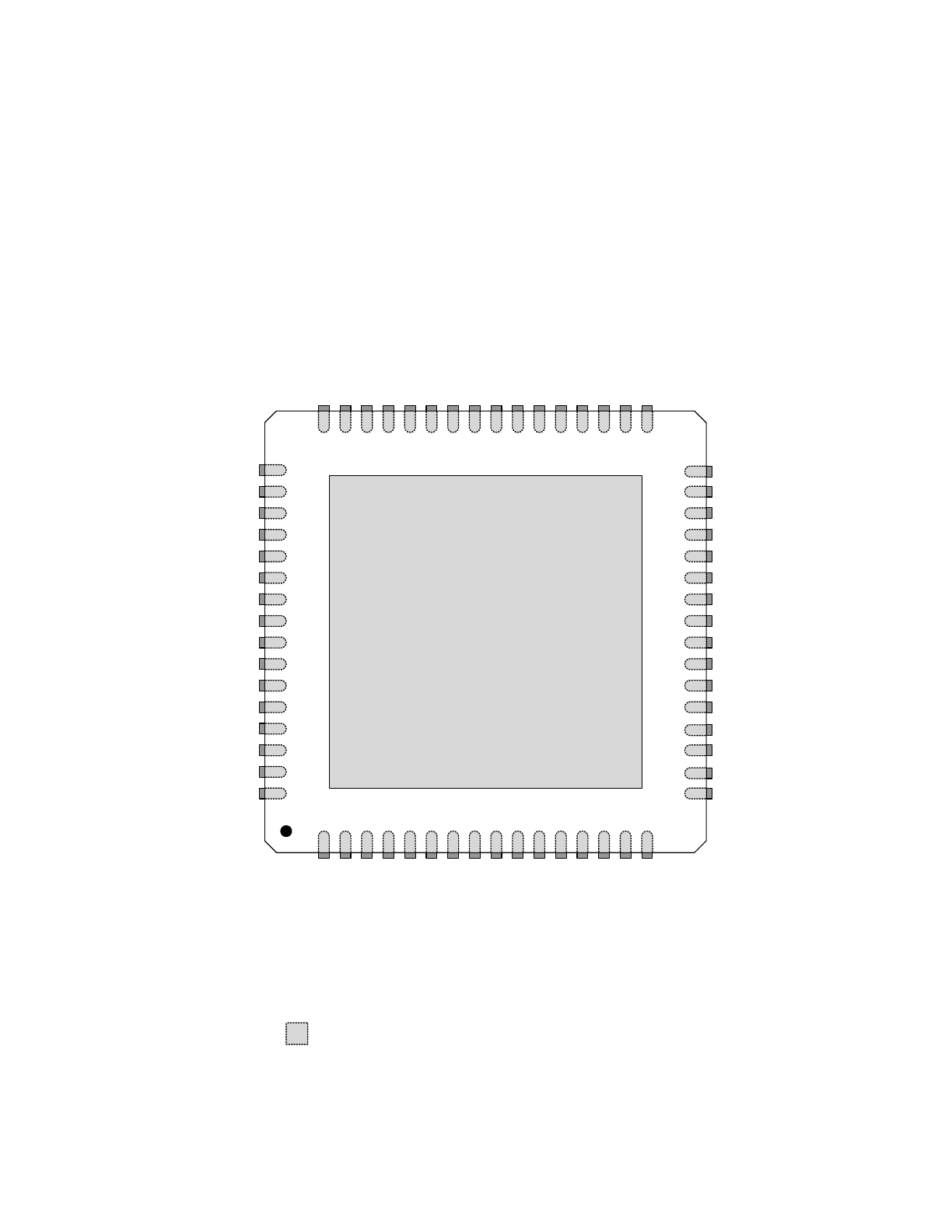
Chapter 2 Pin Configuration
Figure 2.1 USB2517i 64-Pin QFN Diagram
Thermal Slug
(must be connected to VSS)
SMSC
USB2517i
(Top View QFN-64)
Indicates pins on the bottom of the device.
USBDN6_DP/PRT_DIS_P6
54
USBDN7_DM/PRT_DIS_M7
55
USBDN6_DM/PRT_DIS_M6
53
USBDN7_DP/PRT_DIS_P7
56
VDDA33
57
USBUP_DP
59
XTAL2
60
XTAL1/CLKIN
61
RBIAS
64
VDD33PLL
63
VDD18PLL
62
USBUP_DM
58
VDD
A
33
1
USBDN
1
_D
M/PRT_D
IS_M1
2
U
SBD
N
1_
D
P/PR
T_D
IS_P1
3
USBDN
2
_D
M/PRT_D
IS_M2
4
U
SBD
N
2_
D
P/PR
T_D
IS_P2
5
USBDN
3
_D
M/PRT_D
IS_M3
6
U
SBD
N
3_
D
P/PR
T_D
IS_P3
7
USBDN
4
_D
M/PRT_D
IS_M4
8
U
SBD
N
4_
D
P/PR
T_D
IS_P4
9
U
SBD
N
5_
D
P/PR
T_D
IS_P5
10
USBDN
5
_D
M/PRT_D
IS_M5
11
VDD
A
33
12
27
OCS2_N
26
PRTPWR2
25
VDD18
24
VDD33CR
23
OCS4_N
22
PRTPWR3
21
OCS3_N
20
PRTPWR4
19
TEST
29
PRTPWR1
28
OCS1_N
30
PRTPWR5
45
VD
D
3
3
44
SU
SP_IN
D
/LOCAL_
PW
R
/NON
_REM0
43
VBU
S_DET
42
HS
_I
ND
/C
FG_
S
E
L1
41
SC
L/SMBC
LK
/C
FG
_
SEL0
40
SD
A/
SM
BDATA
/NON_
REM1
39
PR
TPWR6
38
OCS6
_N
46
R
ESET_N
37
OCS7
_N
36
PR
TPWR7
35
OCS5
_N
LED_B1_N/BOOST0
50
LED_A1_N/PRT_SWP1
51
LED_A2_N/PRT_SWP2
49
VDDA33
52
47
LED
_B2_
N
/B
O
O
ST1
LE
D_
A
3_N
/P
RT
_S
W
P
3
48
33
LED
_B3_
N
/G
A
N
G_EN
LE
D_
A
4_N
/P
RT
_S
W
P
4
34
18
LED_B5_N
17
LED_A6_N/PRT_SWP6
32
LED_B4_N
31
LED_A5_N/PRT_SWP5
C
F
G
_
SEL2
13
LED
_B6
_N
14
LE
D
_
A
7_N
/P
R
T
_S
W
P
7
15
LED
_B7
_N
16

Industrial Temperature Rated USB 2.0 Hi-Speed 7-Port Hub Controller
Datasheet
Revision 2.8 (03-27-13)
8
SMSC USB2517i
DATASHEET
Chapter 3 Pin Table
3.1
64-Pin List
Table 3.1 USB2517i 64-Pin Table
UPSTREAM USB 2.0 INTERFACES (3 PINS)
USBUP_DP
USBUP_DM
VBUS_DET
DOWNSTREAM 7-PORT USB 2.0 INTERFACES (43 PINS)
USBDN1_DP/
PRT_DIS_P1
USBDN2_DP/
PRT_DIS_P2
USBDN3_DP/
PRT_DIS_P3
USBDN4_DP/
PRT_DIS_P4
USBDN5_DP/
PRT_DIS_P5
USBDN6_DP/
PRT_DIS_P6
USBDN7_DP/
PRT_DIS_P7
USBDN1_DM/
PRT_DIS_M1
USBDN2_DM/
PRT_DIS_M2
USBDN3_DM/
PRT_DIS_M3
USBDN4_DM/
PRT_DIS_M4
USBDN5_DM/
PRT_DIS_M5
USBDN6_DM/
PRT_DIS_M6
USBDN7_DM/
PRT_DIS_M7
LED_A1_N/
PRT_SWP1
LED_A2_N/
PRT_SWP2
LED_A3_N/
PRT_SWP3
LED_A4_N/
PRT_SWP4
LED_A5_N/
PRT_SWP5
LED_A6_N/
PRT_SWP6
LED_A7_N/
PRT_SWP7
LED_B1_N/
BOOST0
LED_B2_N/
BOOST1
LED_B3_N/
GANG_EN
LED_B4_N
LED_B5_N
LED_B6_N
LED_B7_N
PRTPWR1
PRTPWR2
PRTPWR3
PRTPWR4
PRTPWR5
PRTPWR6
PRTPWR7
OCS1_N
OCS2_N
OCS3_N
OCS4_N
OCS5_N
OCS6_N
OCS7_N
RBIAS
SERIAL PORT INTERFACE (4 PINS)
SDA/
SMBDATA/
NON_REM1
SCL/
SMBCLK/
CFG_SEL0
HS_IND/
CFG_SEL1
CFG_SEL2
MISC (5 PINS)
XTAL1/CLKIN
XTAL2
SUSP_IND/
LOCAL_PWR/
NON_REM0
RESET_N
TEST

Industrial Temperature Rated USB 2.0 Hi-Speed 7-Port Hub Controller
Datasheet
SMSC USB2517i
9
Revision 2.8 (03-27-13)
DATASHEET
ANALOG POWER (6 PINS)
VDD18PLL
VDD33PLL
(4) VDDA33
DIGITAL POWER, GROUND (3 PINS)
VDD33
VDD18
VDD33CR
TOTAL 64
Table 3.1 USB2517i 64-Pin Table (continued)
Industrial Temperature Rated USB 2.0 Hi-Speed 7-Port Hub Controller
Datasheet
Revision 2.8 (03-27-13)
10
SMSC USB2517i
DATASHEET
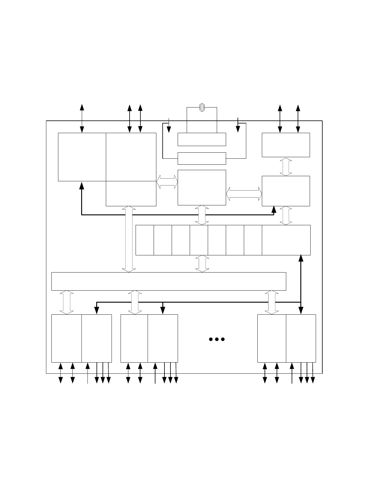
Chapter 4 Block Diagram
Figure 4.1 USB2517i Block Diagram
To Upstream
V
BUS
3.3V
Upstream
PHY
Upstream USB
Data
Repeater
Controller
SIE
Serial
Interface
PLL
24 MHz Crystal
To EEPROM or
SMBus Master
Routing & Port Re-Ordering Logic
SCK
SD
TT
#7
Port
Controller
PHY#1
Port #1
OC
Sense
Switch
Driver
LED
Drivers
USB Data
Downstream
OC Sense
Switch/LED
Drivers
Bus-Power
Detect/V
BUS
Pulse
1.8V
TT
#6
TT
#5
TT
#1
1.8V Reg
PHY#2
Port #2
OC
Sense
Switch
Driver
LED
Drivers
PHY#7
Port #7
OC
Sense
Switch
Driver
LED
Drivers
USB Data
Downstream
OC Sense
Switch/LED
Drivers
USB Data
Downstream
OC Sense
Switch/LED
Drivers
TT
#4
TT
#3
TT
#2