

2016-2017 Microchip Technology Inc.
DS00002084C-page 1
Highlights
• Small Form Factor 4 x 4 mm 44-WFBGA Package
• Integrated Analog Discrete Components Reduce
Bill of Materials and Design Footprint
• USB Power Delivery 2.0 Compliant MAC
• USB Type-C
TM
(1)
Connector Support with
Connection Detection and Control
• I
2
C/SPI
(2)
Interface for CPU/SoC Communication
• USB Type-C™ Alternate Mode Support
• Dual Role Power (DRP) and Role Swap Support
Target Applications
• Notebook Computers
• All-in-One/Desktop PCs
• Smartphones
• Tablets
• Monitors
• Docking Stations
• HDTVs
• Printers
Key Benefits
• Integrated Analog Discrete Components
- VCONN FETs with Rp/Rd Switching
- Dead Battery Rd termination
- Programmable Current Sense for
Overcurrent Conditions
- Voltage Sense for Overvoltage Conditions
• Integrated 5V/3A Port Power Controller (PPC)
- Supports up to 5V/3A on VBUS
- Supplies 500mA, 900mA, 1.5A, and 3.0A per
USB Type-C™ Specification
• Integrated 3.3V Power Switch
- Provides Dead Battery Support
- Automatically Switch between VBUS and
Main +3.3V
• USB Power Delivery MAC
- Compliant with USB Power Delivery
Specification Revision 2.0
- Power Delivery Packet Framing
- CRC Checking/Generation
- 4B/5B Encoding/Decoding
- BMC Encoding/Decoding
- EOP/SOP Generation for PD Frames
- SOP Detection and SOP Header Processing
- Separate RX/TX FIFOs
- Automatic GoodCRC Message Generation
- Automatic Retry Generation
- Error Handling
- Low Standby Power Support via Sleep State
• USB Type-C Cable Detect Logic
- Auto Cable Attach & Orientation Detection
- Routes Baseband Communication to
Respective CC Pin per Detected Orientation
- VCONN Supply Control for Active Cable
- Configurable Downstream Facing Port (DFP)
and Upstream Facing Port (UFP) Modes
- Charging Current Capability Detection
- Detection of Debug Accessory Mode,
Audio Adapter Accessory Mode
• +1.8V I
2
C (1 MHz) Interface Supports Communi-
cation/Configuration via Companion CPU/SoC
• Alternate Mode Support
- DisplayPort
TM
, Thunderbolt
TM
,
and other Major Protocols
• CFG_SEL0 Pin for Selection of Device Mode
• CFG_SEL1 Pin for Selection of I
2
C addresses
(2)
• Power and I/Os
- Integrated 1.8V Voltage Regulator
- 16 Configurable General Purpose I/O Pins
• Software
- C Libraries
• Package
- 44-ball WFBGA (4 x 4 x 0.7 mm)
• Environmental
- Commercial Temperature Range
(0°C to +70°C)
1.
USB Type-C™ and USB-C™ are trademarks of
USB Implementers Forum.
2.
Available only in select UPD360 configurations.
UPD360
Highly Integrated Small Form Factor
USB Type-C™ Power Delivery 2.0 Port Controller

UPD360
DS00002084C-page 2
2016-2017 Microchip Technology Inc.
TO OUR VALUED CUSTOMERS
It is our intention to provide our valued customers with the best documentation possible to ensure successful use of your Microchip
products. To this end, we will continue to improve our publications to better suit your needs. Our publications will be refined and
enhanced as new volumes and updates are introduced.
If you have any questions or comments regarding this publication, please contact the Marketing Communications Department via
E-mail at
docerrors@microchip.com
. We welcome your feedback.
Most Current Documentation
To obtain the most up-to-date version of this documentation, please register at our Worldwide Web site at:
http://www.microchip.com
You can determine the version of a data sheet by examining its literature number found on the bottom outside corner of any page.
The last character of the literature number is the version number, (e.g., DS30000000A is version A of document DS30000000).
Errata
An errata sheet, describing minor operational differences from the data sheet and recommended workarounds, may exist for cur-
rent devices. As device/documentation issues become known to us, we will publish an errata sheet. The errata will specify the
revision of silicon and revision of document to which it applies.
To determine if an errata sheet exists for a particular device, please check with one of the following:
• Microchip’s Worldwide Web site;
http://www.microchip.com
• Your local Microchip sales office (see last page)
When contacting a sales office, please specify which device, revision of silicon and data sheet (include -literature number) you are
using.
Customer Notification System
Register on our web site at
www.microchip.com
to receive the most current information on all of our products.

2016-2017 Microchip Technology Inc.
DS00002084C-page 3
UPD360
Table of Contents
1.0 Preface ............................................................................................................................................................................................ 4
2.0 Introduction ..................................................................................................................................................................................... 7
3.0 Ball Descriptions and Configuration ................................................................................................................................................ 9
4.0 Register Map ................................................................................................................................................................................. 19
5.0 I2C Slave Controller (UPD360-A/UPD360-B Only) ....................................................................................................................... 20
6.0 SPI Slave Controller (UPD360-C Only) ........................................................................................................................................ 26
7.0 Clocks, Resets, and Power Management ..................................................................................................................................... 31
8.0 System Control ............................................................................................................................................................................. 35
9.0 Cable Plug Orientation and Detection ........................................................................................................................................... 68
10.0 Baseband CC Interface (BCI) ................................................................................................................................................... 107
11.0 Power Delivery MAC ................................................................................................................................................................. 111
12.0 USB Port Power Controller (PPC) ............................................................................................................................................ 171
13.0 Power Switch ............................................................................................................................................................................ 182
14.0 DisplayPort Hot Plug Detect (HPD) .......................................................................................................................................... 195
15.0 Watchdog Timer (WDT) ............................................................................................................................................................ 202
16.0 Operational Characteristics ....................................................................................................................................................... 206
17.0 Package Information ................................................................................................................................................................. 214
Appendix A: Data Sheet Revision History ......................................................................................................................................... 217
The Microchip Web Site .................................................................................................................................................................... 218
Customer Change Notification Service ............................................................................................................................................. 218
Customer Support ............................................................................................................................................................................. 218
Product Identification System ........................................................................................................................................................... 219

UPD360
DS00002084C-page 4
2016-2017 Microchip Technology Inc.
1.0
PREFACE
1.1
Glossary of Terms
TABLE 1-1:
GLOSSARY OF TERMS
Term
Definition
ADC
Analog to Digital Converter
AFE
Analog Front End
BCI
Baseband CC Interface
Billboard
USB Billboard Device. A required USB device class for UFPs which support Alternate Modes
in order to provide product information to the USB Host.
BIST
Built-In Self Test
BMC
Bi-phase Mark Coding
Byte
8-bits
CC
Generic reference to USB Type-C
™
Cable / Connector CC1/CC2 pins
CSR
Control and Status Register
DB
Dead Battery
DFP
Downstream Facing Port (USB Type-C™ Specification definition)
DP
DisplayPort (a VESA standard interface)
DPM
Device Policy Manager (PD Specification definition)
DRP
Dual Role Power (USB Type-C™ Specification definition)
DWORD
32-bits
EC
Embedded Controller
EP
USB Endpoint
FIFO
First In First Out buffer
FW
Firmware
FS
Full-Speed
Host
External system (Includes processor, application software, etc.)
HPD
Hot-Plug Detect functionality as defined by DisplayPort and DisplayPort Alternate Mode speci-
fications
HS
High-Speed
HW
Hardware (Refers to function implemented by the device)
IC
Integrated Circuit
IFC
InterFrame Gap
LDO
Linear Drop-Out regulator
MAC
Media Access Controller
Microchip
Microchip Technology Incorporated
N/A
Not Applicable
OCS
Over-Current Sense
PCS
Physical Coding Sublayer
PD / UPD
USB Power Delivery
PIO
General Purpose I/O
PMIC
Power Management Integrated Circuit
POR
Power-On Reset
PRBS
Pseudo Random Binary Sequence
QWORD
64-bits
SA
Source Address

2016-2017 Microchip Technology Inc.
DS00002084C-page 5
UPD360
1.2
Buffer Types
SBU
SideBand Use
SCSR
System Control and Status Register
SPM
System Policy Manager (PD Specification definition)
SS
SuperSpeed
SVDM
Standard/Vendor Defined Message (PD Specification definition)
SVID
Standard/Vendor IDentity (PD Specification definition)
TCPC
USB Type-C™ Port Controller
UFP
Upstream Facing Port (USB Type-C™ Specification definition)
USB
Universal Serial Bus
USB Type-C™
USB Type-C™ Cable / Connector
VDO
Vendor-defined Object (PD Specification definition)
VSM
Vendor Specific Messaging
WORD
16-bits
ZLP
Zero Length USB Packet
TABLE 1-2:
BUFFER TYPES
Buffer Type
Description
IS
Schmitt-triggered input
I2C
I
2
C interface
O8
Output with 8 mA sink and 8 mA source
OD8
Open-drain output with 8 mA sink
PU
70k (typical) internal pull-up. Unless otherwise noted in the pin description, internal pull-ups
are always enabled.
Note:
Internal pull-up resistors prevent unconnected inputs from floating. Do not rely on
internal resistors to drive signals external to the device. When connected to a load
that must be pulled high, an external resistor must be added.
PD
70k (typical) internal pull-down. Unless otherwise noted in the pin description, internal pull-
downs are always enabled.
Note:
Internal pull-down resistors prevent unconnected inputs from floating. Do not rely
on internal resistors to drive signals external to the device. When connected to a
load that must be pulled low, an external resistor must be added.
AIO
Analog bidirectional
P
Power pin
Note:
Digital signals are not 5V tolerant unless specified.
Note:
Refer to
Section 16.5, "DC Characteristics," on page 208
for the electrical characteristics of the various buf-
fers.
TABLE 1-1:
GLOSSARY OF TERMS (CONTINUED)
Term
Definition

UPD360
DS00002084C-page 6
2016-2017 Microchip Technology Inc.
1.3
Register Nomenclature
1.4
References
• NXP I
2
C-Bus Specification (UM10204, April 4, 2014): www.nxp.com/documents/user_manual/UM10204.pdf
• USB Power Delivery and USB Type-C™ Specifications: http://www.usb.org/developers/docs/usb_31_102015.zip
• VESA DisplayPort Alternate Mode Specification 1.0: http://www.vesa.org
TABLE 1-3:
REGISTER NOMENCLATURE
Register Bit Type Notation
Register Bit Description
R
Read: A register or bit with this attribute can be read.
W
Write: A register or bit with this attribute can be written.
RO
Read only: Read only. Writes have no effect.
RS
Read to Set: This bit is set on read.
WO
Write only: If a register or bit is write-only, reads will return unspecified data.
W1S
Write One to Set: Writing a one sets the value. Writing a zero has no effect.
W1C
Write One to Clear: Writing a one clears the value. Writing a zero has no effect.
WC
Write Anything to Clear: Writing anything clears the value.
LL
Latch Low: Clear on read of register.
LH
Latch High: Clear on read of register.
SC
Self-Clearing: Contents are self-cleared after the being set. Writes of zero have no
effect. Contents can be read.
RO/LH
Read Only, Latch High: Bits with this attribute will stay high until the bit is read. After it
is read, the bit will remain high, but will change to low if the condition that caused the
bit to go high is removed. If the bit has not been read, the bit will remain high regard-
less of a change to the high condition.
NASR
Not Affected by Software Reset. The state of NASR bits do not change on assertion
of a software reset.
RESERVED
Reserved Field: Reserved fields must be written with zeros, unless otherwise indi-
cated, to ensure future compatibility. The value of reserved bits is not guaranteed on a
read.
2016-2017 Microchip Technology Inc.
DS00002084C-page 7
UPD360
2.0
INTRODUCTION
2.1
General Description
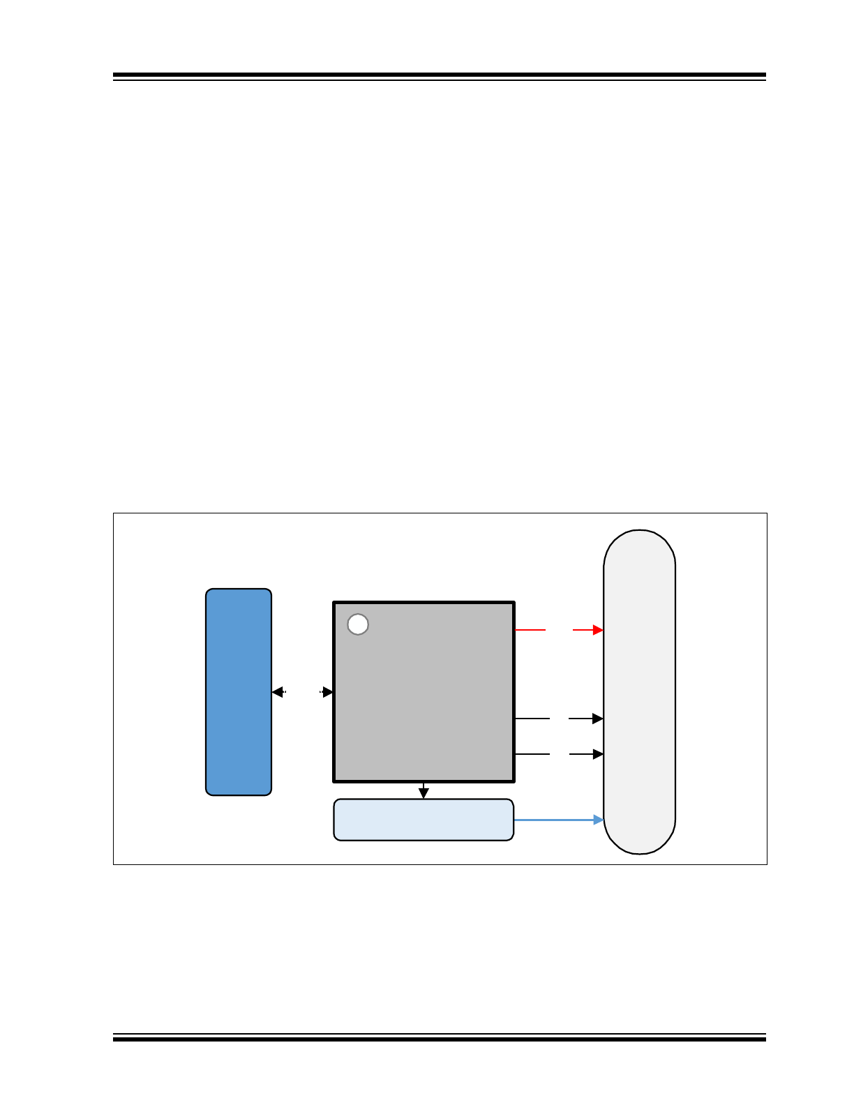
The UPD360 is a highly integrated, small form factor USB Type-C Power Delivery (PD) Port Controller designed to
adhere to the USB Type-C™ Cable and Connector Specification and USB Power Delivery 2.0 Specification. The
UPD360 provides cable plug orientation and detection for a USB Type-C receptacle and implements baseband commu-
nication with a partner USB Type-C device via the integrated USB Power Delivery 2.0 MAC. The device can function in
Standalone UFP/DFP modes, or utilize the integrated I
2
C/SPI interface to connect to a companion CPU/SoC (depen-
dent on device version, see
Section 2.2, "UPD360 Family Differences Summary"
).
Additionally, the UPD360 integrates many of the analog discrete components required for USB Type-C PD applications,
including two VCONN FETs with Rp/Rd switching, a port power controller that supports up to 5V/3A on VBUS, and cur-
rent and voltage sense circuitry for over-voltage/current detection. By integrating many of the analog discrete compo-
nents required for USB Type-C PD applications, the UPD360 provides a low cost, low power, small footprint (4 x 4 mm)
solution for consumer (notebooks, desktop PCs, smartphones, tablets, monitors, docking stations) applications.
To enable the UPD360 to efficiently support dead battery use cases, an integrated power switch is provided to select
between two external 3.3V supplies (VBUS and main). This effectively allows connection detection and system wakeup
without external processor intervention (external processor in sleep mode).
The UPD360 is also capable of negotiating alternate modes over USB Type-C connectors using the Power Delivery 2.0
protocol. Both DisplayPort and Thunderbolt operation over USB Type-C connectors are supported in addition to other
major protocols.
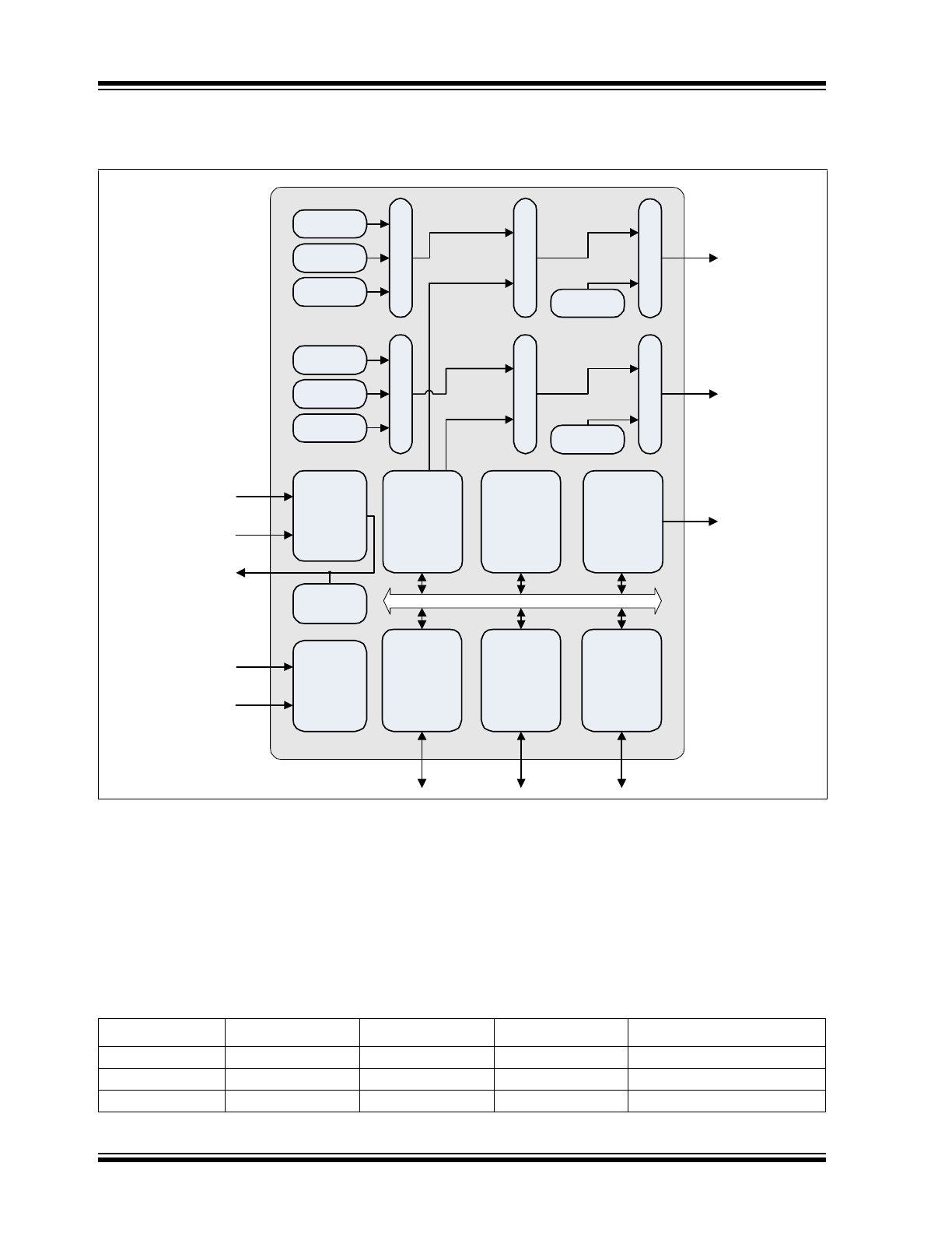
A system diagram utilizing the UPD360 is shown in
Figure 2-1
. An internal block diagram of the UPD360 is shown in
Figure 2-2
.
FIGURE 2-1:
SYSTEM BLOCK DIAGRAM
Microchip
UPD360
US
B
Ty
p
e
‐C
TM
Co
nn
ec
to
r
VBUS
CC1
CC2
SoC
I
2
C/SPI
USB Crossbar /
Alternate Mode Switches
UPD360
DS00002084C-page 8
2016-2017 Microchip Technology Inc.
2.2
UPD360 Family Differences Summary
The UPD360 is available in three versions:
• UPD360-A
• UPD360-B
• UPD360-C
A summary of the differences between these versions is provided in
Table 2-1
. Device specific features that do no per-
tain to the entire UPD360 family are called out independently throughout this document. For ordering information, refer
to the
Product Identification System on page 219
.
FIGURE 2-2:
INTERNAL BLOCK DIAGRAM
TABLE 2-1:
UPD360 FAMILY DIFFERENCES
Device
+1.8V I
2
C Interface +3.3V I
2
C Interface
SPI Interface
Standalone UFP/DFP Mode
UPD360-A
X
X
UPD360-B
X
X
UPD360-C
X
UPD360
3V3_ALW
Rp‐Low
Rd
Rp‐High
Rp‐Low
Rd
Baseband
CC
Interface
VCONN(5V)
VCONN(5V)
Auto
Power
Switch
3V3_VBUS
1.8V LDO
Regulator
VSW
CC1
CC2
5V/3A
Port
Power
Controller
VBUS
I
2
C
Controller
(UPD360‐A: +1.8V)
(UPD360‐B: +3.3V)
GPIOs
(16x)
OCS_COMP1
Over‐
Current
Detection
OCS_COMP2
I
2
C
(UPD360‐A/B Only)
Rp‐High
Mu
x
Mu
x
Mu
x
Mu
x
FE
T
FE
T
SPI
Controller
(UPD360‐C Only)
SPI
(UPD360‐C Only)
Power
Delivery
2.0
MAC
GPIO[0:15]
(GPIO0 not available
in UPD360‐C)
2016-2017 Microchip Technology Inc.
DS00002084C-page 9
UPD360
3.0
BALL DESCRIPTIONS AND CONFIGURATION
3.1
Ball Assignments
The ball assignments for the UPD360-A/UPD360-B are detailed in
Section 3.1.1, "UPD360-A/UPD360-B Ball Assign-
ments," on page 9
. The ball assignments for the UPD360-C are detailed in
Section 3.1.1, "UPD360-A/UPD360-B Ball
Assignments," on page 9
. For information on the differences between the UPD360 family of devices, refer to
Section
2.2, "UPD360 Family Differences Summary," on page 8
.
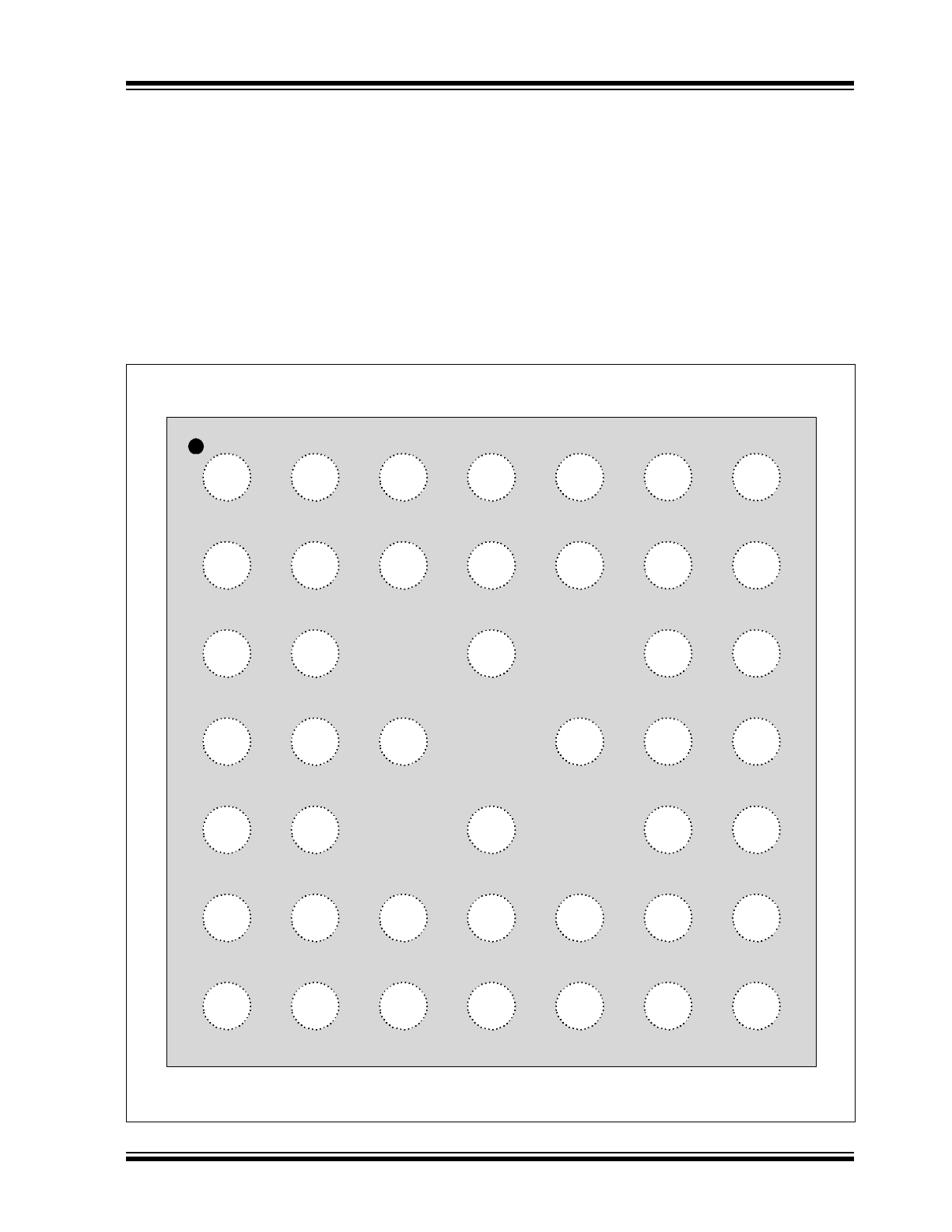
3.1.1
UPD360-A/UPD360-B BALL ASSIGNMENTS
The device ball diagram for the UPD360-A/UPD360-B can be seen in
Figure 3-1
.
Table 3-1
provides a UPD360-A/
UPD360-B ball assignment table. Ball descriptions are provided in
Section 3.2, "Ball Descriptions"
.
FIGURE 3-1:
UPD360-A/UPD360-B BALL ASSIGNMENTS (TOP VIEW)
VBUS
VBUS
CC2
CC1
CFG_SEL 0
Top of UPD360-A/UPD360-B 44-WFBGA Package
A
B
C
D
E
1
2
3
4
5
6
VS
VBUS_DET
CC2_DB_EN
CC1_DB_EN
OCS_COMP1
VS
GPIO9*
VSS
NC
GPO10*
VSS
VSS
GPIO13*
GPIO11*/
DISCHARGE
VSS
GPIO 14*
VDD33IO
GPIO5
GPIO7
GPIO4
7
GPIO15*
GPIO12*
GPIO 8
RESET_N
GPIO 6
3V3_ALW
VSW
F
G
PWR_DN
3V3_VBUS
VDD33IO
VDD18_CAP
IRQ_N
I2C_DAT
CFG_SEL 1
I2C_CLK
GPO1
GPIO0
GPIO3/HPD
GPIO 2/
OCS_COMP2
*The GPIO[9:15] balls provide alternate functions when in Standalone DFP or Standalone UFP modes
.

UPD360
DS00002084C-page 10
2016-2017 Microchip Technology Inc.
Note 3-1
This ball provides alternate functions when in Standalone DFP and Standalone UFP Modes. Refer to
Section 3.1.1.1, "UPD360-A/UPD360-B GPIO[9:15] Functions in Standalone DFP/UFP Modes"
for
additional information.
Note 3-2
This general purpose signal can only function as an output and must not be pulled-up
externally during RESET_N assertion.
TABLE 3-1:
UPD360-A/UPD360-B BALL ASSIGNMENTS
Ball
Pin Name
Ball
Pin Name
A1
VBUS
D5
VSS
A2
VS
D6
GPIO7
A3
VS
D7
RESET_N
A4
NC
E1
CFG_SEL0
A5
GPIO13
(
Note 3-1
)
E2
OCS_COMP1
A6
GPIO14
(
Note 3-1
)
E4
VSS
A7
GPIO15
(
Note 3-1
)
E6
GPIO4
B1
VBUS
E7
GPIO6
B2
VBUS_DET
F1
3V3_ALW
B3
GPIO9
(
Note 3-1
)
F2
PWR_DN
B4
GPO10
(
Note 3-1
) (
Note 3-2
)
F3
VDD33IO
B5
GPIO11/DISCHARGE
(
Note 3-1
)
F4
IRQ_N
B6
VDD33IO
F5
CFG_SEL1
B7
GPIO12
(
Note 3-1
)
F6
GPO1
(
Note 3-2
)
C1
CC2
F7
GPIO3/HPD
C2
CC2_DB_EN
G1
VSW
C4
VSS
G2
3V3_VBUS
C6
GPIO5
G3
VDD18_CAP
C7
GPIO8
G4
I2C_DAT
D1
CC1
G5
I2C_CLK
D2
CC1_DB_EN
G6
GPIO0
D3
VSS
G7
GPIO2/OCS_COMP2
2016-2017 Microchip Technology Inc.
DS00002084C-page 1
Highlights
• Small Form Factor 4 x 4 mm 44-WFBGA Package
• Integrated Analog Discrete Components Reduce
Bill of Materials and Design Footprint
• USB Power Delivery 2.0 Compliant MAC
• USB Type-C
TM
(1)
Connector Support with
Connection Detection and Control
• I
2
C/SPI
(2)
Interface for CPU/SoC Communication
• USB Type-C™ Alternate Mode Support
• Dual Role Power (DRP) and Role Swap Support
Target Applications
• Notebook Computers
• All-in-One/Desktop PCs
• Smartphones
• Tablets
• Monitors
• Docking Stations
• HDTVs
• Printers
Key Benefits
• Integrated Analog Discrete Components
- VCONN FETs with Rp/Rd Switching
- Dead Battery Rd termination
- Programmable Current Sense for
Overcurrent Conditions
- Voltage Sense for Overvoltage Conditions
• Integrated 5V/3A Port Power Controller (PPC)
- Supports up to 5V/3A on VBUS
- Supplies 500mA, 900mA, 1.5A, and 3.0A per
USB Type-C™ Specification
• Integrated 3.3V Power Switch
- Provides Dead Battery Support
- Automatically Switch between VBUS and
Main +3.3V
• USB Power Delivery MAC
- Compliant with USB Power Delivery
Specification Revision 2.0
- Power Delivery Packet Framing
- CRC Checking/Generation
- 4B/5B Encoding/Decoding
- BMC Encoding/Decoding
- EOP/SOP Generation for PD Frames
- SOP Detection and SOP Header Processing
- Separate RX/TX FIFOs
- Automatic GoodCRC Message Generation
- Automatic Retry Generation
- Error Handling
- Low Standby Power Support via Sleep State
• USB Type-C Cable Detect Logic
- Auto Cable Attach & Orientation Detection
- Routes Baseband Communication to
Respective CC Pin per Detected Orientation
- VCONN Supply Control for Active Cable
- Configurable Downstream Facing Port (DFP)
and Upstream Facing Port (UFP) Modes
- Charging Current Capability Detection
- Detection of Debug Accessory Mode,
Audio Adapter Accessory Mode
• +1.8V I
2
C (1 MHz) Interface Supports Communi-
cation/Configuration via Companion CPU/SoC
• Alternate Mode Support
- DisplayPort
TM
, Thunderbolt
TM
,
and other Major Protocols
• CFG_SEL0 Pin for Selection of Device Mode
• CFG_SEL1 Pin for Selection of I
2
C addresses
(2)
• Power and I/Os
- Integrated 1.8V Voltage Regulator
- 16 Configurable General Purpose I/O Pins
• Software
- C Libraries
• Package
- 44-ball WFBGA (4 x 4 x 0.7 mm)
• Environmental
- Commercial Temperature Range
(0°C to +70°C)
1.
USB Type-C™ and USB-C™ are trademarks of
USB Implementers Forum.
2.
Available only in select UPD360 configurations.
UPD360
Highly Integrated Small Form Factor
USB Type-C™ Power Delivery 2.0 Port Controller
UPD360
DS00002084C-page 2
2016-2017 Microchip Technology Inc.
TO OUR VALUED CUSTOMERS
It is our intention to provide our valued customers with the best documentation possible to ensure successful use of your Microchip
products. To this end, we will continue to improve our publications to better suit your needs. Our publications will be refined and
enhanced as new volumes and updates are introduced.
If you have any questions or comments regarding this publication, please contact the Marketing Communications Department via
E-mail at
docerrors@microchip.com
. We welcome your feedback.
Most Current Documentation
To obtain the most up-to-date version of this documentation, please register at our Worldwide Web site at:
http://www.microchip.com
You can determine the version of a data sheet by examining its literature number found on the bottom outside corner of any page.
The last character of the literature number is the version number, (e.g., DS30000000A is version A of document DS30000000).
Errata
An errata sheet, describing minor operational differences from the data sheet and recommended workarounds, may exist for cur-
rent devices. As device/documentation issues become known to us, we will publish an errata sheet. The errata will specify the
revision of silicon and revision of document to which it applies.
To determine if an errata sheet exists for a particular device, please check with one of the following:
• Microchip’s Worldwide Web site;
http://www.microchip.com
• Your local Microchip sales office (see last page)
When contacting a sales office, please specify which device, revision of silicon and data sheet (include -literature number) you are
using.
Customer Notification System
Register on our web site at
www.microchip.com
to receive the most current information on all of our products.
2016-2017 Microchip Technology Inc.
DS00002084C-page 3
UPD360
Table of Contents
1.0 Preface ............................................................................................................................................................................................ 4
2.0 Introduction ..................................................................................................................................................................................... 7
3.0 Ball Descriptions and Configuration ................................................................................................................................................ 9
4.0 Register Map ................................................................................................................................................................................. 19
5.0 I2C Slave Controller (UPD360-A/UPD360-B Only) ....................................................................................................................... 20
6.0 SPI Slave Controller (UPD360-C Only) ........................................................................................................................................ 26
7.0 Clocks, Resets, and Power Management ..................................................................................................................................... 31
8.0 System Control ............................................................................................................................................................................. 35
9.0 Cable Plug Orientation and Detection ........................................................................................................................................... 68
10.0 Baseband CC Interface (BCI) ................................................................................................................................................... 107
11.0 Power Delivery MAC ................................................................................................................................................................. 111
12.0 USB Port Power Controller (PPC) ............................................................................................................................................ 171
13.0 Power Switch ............................................................................................................................................................................ 182
14.0 DisplayPort Hot Plug Detect (HPD) .......................................................................................................................................... 195
15.0 Watchdog Timer (WDT) ............................................................................................................................................................ 202
16.0 Operational Characteristics ....................................................................................................................................................... 206
17.0 Package Information ................................................................................................................................................................. 214
Appendix A: Data Sheet Revision History ......................................................................................................................................... 217
The Microchip Web Site .................................................................................................................................................................... 218
Customer Change Notification Service ............................................................................................................................................. 218
Customer Support ............................................................................................................................................................................. 218
Product Identification System ........................................................................................................................................................... 219
UPD360
DS00002084C-page 4
2016-2017 Microchip Technology Inc.
1.0
PREFACE
1.1
Glossary of Terms
TABLE 1-1:
GLOSSARY OF TERMS
Term
Definition
ADC
Analog to Digital Converter
AFE
Analog Front End
BCI
Baseband CC Interface
Billboard
USB Billboard Device. A required USB device class for UFPs which support Alternate Modes
in order to provide product information to the USB Host.
BIST
Built-In Self Test
BMC
Bi-phase Mark Coding
Byte
8-bits
CC
Generic reference to USB Type-C
™
Cable / Connector CC1/CC2 pins
CSR
Control and Status Register
DB
Dead Battery
DFP
Downstream Facing Port (USB Type-C™ Specification definition)
DP
DisplayPort (a VESA standard interface)
DPM
Device Policy Manager (PD Specification definition)
DRP
Dual Role Power (USB Type-C™ Specification definition)
DWORD
32-bits
EC
Embedded Controller
EP
USB Endpoint
FIFO
First In First Out buffer
FW
Firmware
FS
Full-Speed
Host
External system (Includes processor, application software, etc.)
HPD
Hot-Plug Detect functionality as defined by DisplayPort and DisplayPort Alternate Mode speci-
fications
HS
High-Speed
HW
Hardware (Refers to function implemented by the device)
IC
Integrated Circuit
IFC
InterFrame Gap
LDO
Linear Drop-Out regulator
MAC
Media Access Controller
Microchip
Microchip Technology Incorporated
N/A
Not Applicable
OCS
Over-Current Sense
PCS
Physical Coding Sublayer
PD / UPD
USB Power Delivery
PIO
General Purpose I/O
PMIC
Power Management Integrated Circuit
POR
Power-On Reset
PRBS
Pseudo Random Binary Sequence
QWORD
64-bits
SA
Source Address
2016-2017 Microchip Technology Inc.
DS00002084C-page 5
UPD360
1.2
Buffer Types
SBU
SideBand Use
SCSR
System Control and Status Register
SPM
System Policy Manager (PD Specification definition)
SS
SuperSpeed
SVDM
Standard/Vendor Defined Message (PD Specification definition)
SVID
Standard/Vendor IDentity (PD Specification definition)
TCPC
USB Type-C™ Port Controller
UFP
Upstream Facing Port (USB Type-C™ Specification definition)
USB
Universal Serial Bus
USB Type-C™
USB Type-C™ Cable / Connector
VDO
Vendor-defined Object (PD Specification definition)
VSM
Vendor Specific Messaging
WORD
16-bits
ZLP
Zero Length USB Packet
TABLE 1-2:
BUFFER TYPES
Buffer Type
Description
IS
Schmitt-triggered input
I2C
I
2
C interface
O8
Output with 8 mA sink and 8 mA source
OD8
Open-drain output with 8 mA sink
PU
70k (typical) internal pull-up. Unless otherwise noted in the pin description, internal pull-ups
are always enabled.
Note:
Internal pull-up resistors prevent unconnected inputs from floating. Do not rely on
internal resistors to drive signals external to the device. When connected to a load
that must be pulled high, an external resistor must be added.
PD
70k (typical) internal pull-down. Unless otherwise noted in the pin description, internal pull-
downs are always enabled.
Note:
Internal pull-down resistors prevent unconnected inputs from floating. Do not rely
on internal resistors to drive signals external to the device. When connected to a
load that must be pulled low, an external resistor must be added.
AIO
Analog bidirectional
P
Power pin
Note:
Digital signals are not 5V tolerant unless specified.
Note:
Refer to
Section 16.5, "DC Characteristics," on page 208
for the electrical characteristics of the various buf-
fers.
TABLE 1-1:
GLOSSARY OF TERMS (CONTINUED)
Term
Definition
UPD360
DS00002084C-page 6
2016-2017 Microchip Technology Inc.
1.3
Register Nomenclature
1.4
References
• NXP I
2
C-Bus Specification (UM10204, April 4, 2014): www.nxp.com/documents/user_manual/UM10204.pdf
• USB Power Delivery and USB Type-C™ Specifications: http://www.usb.org/developers/docs/usb_31_102015.zip
• VESA DisplayPort Alternate Mode Specification 1.0: http://www.vesa.org
TABLE 1-3:
REGISTER NOMENCLATURE
Register Bit Type Notation
Register Bit Description
R
Read: A register or bit with this attribute can be read.
W
Write: A register or bit with this attribute can be written.
RO
Read only: Read only. Writes have no effect.
RS
Read to Set: This bit is set on read.
WO
Write only: If a register or bit is write-only, reads will return unspecified data.
W1S
Write One to Set: Writing a one sets the value. Writing a zero has no effect.
W1C
Write One to Clear: Writing a one clears the value. Writing a zero has no effect.
WC
Write Anything to Clear: Writing anything clears the value.
LL
Latch Low: Clear on read of register.
LH
Latch High: Clear on read of register.
SC
Self-Clearing: Contents are self-cleared after the being set. Writes of zero have no
effect. Contents can be read.
RO/LH
Read Only, Latch High: Bits with this attribute will stay high until the bit is read. After it
is read, the bit will remain high, but will change to low if the condition that caused the
bit to go high is removed. If the bit has not been read, the bit will remain high regard-
less of a change to the high condition.
NASR
Not Affected by Software Reset. The state of NASR bits do not change on assertion
of a software reset.
RESERVED
Reserved Field: Reserved fields must be written with zeros, unless otherwise indi-
cated, to ensure future compatibility. The value of reserved bits is not guaranteed on a
read.
2016-2017 Microchip Technology Inc.
DS00002084C-page 7
UPD360
2.0
INTRODUCTION
2.1
General Description
The UPD360 is a highly integrated, small form factor USB Type-C Power Delivery (PD) Port Controller designed to
adhere to the USB Type-C™ Cable and Connector Specification and USB Power Delivery 2.0 Specification. The
UPD360 provides cable plug orientation and detection for a USB Type-C receptacle and implements baseband commu-
nication with a partner USB Type-C device via the integrated USB Power Delivery 2.0 MAC. The device can function in
Standalone UFP/DFP modes, or utilize the integrated I
2
C/SPI interface to connect to a companion CPU/SoC (depen-
dent on device version, see
Section 2.2, "UPD360 Family Differences Summary"
).
Additionally, the UPD360 integrates many of the analog discrete components required for USB Type-C PD applications,
including two VCONN FETs with Rp/Rd switching, a port power controller that supports up to 5V/3A on VBUS, and cur-
rent and voltage sense circuitry for over-voltage/current detection. By integrating many of the analog discrete compo-
nents required for USB Type-C PD applications, the UPD360 provides a low cost, low power, small footprint (4 x 4 mm)
solution for consumer (notebooks, desktop PCs, smartphones, tablets, monitors, docking stations) applications.
To enable the UPD360 to efficiently support dead battery use cases, an integrated power switch is provided to select
between two external 3.3V supplies (VBUS and main). This effectively allows connection detection and system wakeup
without external processor intervention (external processor in sleep mode).
The UPD360 is also capable of negotiating alternate modes over USB Type-C connectors using the Power Delivery 2.0
protocol. Both DisplayPort and Thunderbolt operation over USB Type-C connectors are supported in addition to other
major protocols.
A system diagram utilizing the UPD360 is shown in
Figure 2-1
. An internal block diagram of the UPD360 is shown in
Figure 2-2
.
FIGURE 2-1:
SYSTEM BLOCK DIAGRAM
Microchip
UPD360
US
B
Ty
p
e
‐C
TM
Co
nn
ec
to
r
VBUS
CC1
CC2
SoC
I
2
C/SPI
USB Crossbar /
Alternate Mode Switches
UPD360
DS00002084C-page 8
2016-2017 Microchip Technology Inc.
2.2
UPD360 Family Differences Summary
The UPD360 is available in three versions:
• UPD360-A
• UPD360-B
• UPD360-C
A summary of the differences between these versions is provided in
Table 2-1
. Device specific features that do no per-
tain to the entire UPD360 family are called out independently throughout this document. For ordering information, refer
to the
Product Identification System on page 219
.
FIGURE 2-2:
INTERNAL BLOCK DIAGRAM
TABLE 2-1:
UPD360 FAMILY DIFFERENCES
Device
+1.8V I
2
C Interface +3.3V I
2
C Interface
SPI Interface
Standalone UFP/DFP Mode
UPD360-A
X
X
UPD360-B
X
X
UPD360-C
X
UPD360
3V3_ALW
Rp‐Low
Rd
Rp‐High
Rp‐Low
Rd
Baseband
CC
Interface
VCONN(5V)
VCONN(5V)
Auto
Power
Switch
3V3_VBUS
1.8V LDO
Regulator
VSW
CC1
CC2
5V/3A
Port
Power
Controller
VBUS
I
2
C
Controller
(UPD360‐A: +1.8V)
(UPD360‐B: +3.3V)
GPIOs
(16x)
OCS_COMP1
Over‐
Current
Detection
OCS_COMP2
I
2
C
(UPD360‐A/B Only)
Rp‐High
Mu
x
Mu
x
Mu
x
Mu
x
FE
T
FE
T
SPI
Controller
(UPD360‐C Only)
SPI
(UPD360‐C Only)
Power
Delivery
2.0
MAC
GPIO[0:15]
(GPIO0 not available
in UPD360‐C)
2016-2017 Microchip Technology Inc.
DS00002084C-page 9
UPD360
3.0
BALL DESCRIPTIONS AND CONFIGURATION
3.1
Ball Assignments
The ball assignments for the UPD360-A/UPD360-B are detailed in
Section 3.1.1, "UPD360-A/UPD360-B Ball Assign-
ments," on page 9
. The ball assignments for the UPD360-C are detailed in
Section 3.1.1, "UPD360-A/UPD360-B Ball
Assignments," on page 9
. For information on the differences between the UPD360 family of devices, refer to
Section
2.2, "UPD360 Family Differences Summary," on page 8
.
3.1.1
UPD360-A/UPD360-B BALL ASSIGNMENTS
The device ball diagram for the UPD360-A/UPD360-B can be seen in
Figure 3-1
.
Table 3-1
provides a UPD360-A/
UPD360-B ball assignment table. Ball descriptions are provided in
Section 3.2, "Ball Descriptions"
.
FIGURE 3-1:
UPD360-A/UPD360-B BALL ASSIGNMENTS (TOP VIEW)
VBUS
VBUS
CC2
CC1
CFG_SEL 0
Top of UPD360-A/UPD360-B 44-WFBGA Package
A
B
C
D
E
1
2
3
4
5
6
VS
VBUS_DET
CC2_DB_EN
CC1_DB_EN
OCS_COMP1
VS
GPIO9*
VSS
NC
GPO10*
VSS
VSS
GPIO13*
GPIO11*/
DISCHARGE
VSS
GPIO 14*
VDD33IO
GPIO5
GPIO7
GPIO4
7
GPIO15*
GPIO12*
GPIO 8
RESET_N
GPIO 6
3V3_ALW
VSW
F
G
PWR_DN
3V3_VBUS
VDD33IO
VDD18_CAP
IRQ_N
I2C_DAT
CFG_SEL 1
I2C_CLK
GPO1
GPIO0
GPIO3/HPD
GPIO 2/
OCS_COMP2
*The GPIO[9:15] balls provide alternate functions when in Standalone DFP or Standalone UFP modes
.
UPD360
DS00002084C-page 10
2016-2017 Microchip Technology Inc.
Note 3-1
This ball provides alternate functions when in Standalone DFP and Standalone UFP Modes. Refer to
Section 3.1.1.1, "UPD360-A/UPD360-B GPIO[9:15] Functions in Standalone DFP/UFP Modes"
for
additional information.
Note 3-2
This general purpose signal can only function as an output and must not be pulled-up
externally during RESET_N assertion.
TABLE 3-1:
UPD360-A/UPD360-B BALL ASSIGNMENTS
Ball
Pin Name
Ball
Pin Name
A1
VBUS
D5
VSS
A2
VS
D6
GPIO7
A3
VS
D7
RESET_N
A4
NC
E1
CFG_SEL0
A5
GPIO13
(
Note 3-1
)
E2
OCS_COMP1
A6
GPIO14
(
Note 3-1
)
E4
VSS
A7
GPIO15
(
Note 3-1
)
E6
GPIO4
B1
VBUS
E7
GPIO6
B2
VBUS_DET
F1
3V3_ALW
B3
GPIO9
(
Note 3-1
)
F2
PWR_DN
B4
GPO10
(
Note 3-1
) (
Note 3-2
)
F3
VDD33IO
B5
GPIO11/DISCHARGE
(
Note 3-1
)
F4
IRQ_N
B6
VDD33IO
F5
CFG_SEL1
B7
GPIO12
(
Note 3-1
)
F6
GPO1
(
Note 3-2
)
C1
CC2
F7
GPIO3/HPD
C2
CC2_DB_EN
G1
VSW
C4
VSS
G2
3V3_VBUS
C6
GPIO5
G3
VDD18_CAP
C7
GPIO8
G4
I2C_DAT
D1
CC1
G5
I2C_CLK
D2
CC1_DB_EN
G6
GPIO0
D3
VSS
G7
GPIO2/OCS_COMP2