
2001-2015 Microchip Technology Inc.
DS20001439E-page 1
TC620/TC621
Features
• User Programmable Hysteresis and
Temperature Set Point
• Easily Programs with Two External Resistors
• Wide Temperature Detection Range:
- 0°C to 70°C: (TC620/TC621CCX)
- -40°C to +125°C: (TC620/TC621CVX)
- -40°C to +85°C: (TC620/TC621CEX)
• Onboard Temperature Sensing Applications
(TC620X)
• External NTC Thermistor for Remote Sensing
Applications (TC621X)
• Available in 8-Pin PDIP and SOIC Packages
Applications
• Power Supply Over Temperature Detection
• Consumer Equipment
• Temperature Regulators
• CPU Thermal Protection
Device Selection Table
Note:
*The part code will be C or H (see
Functional Block Diagrams).
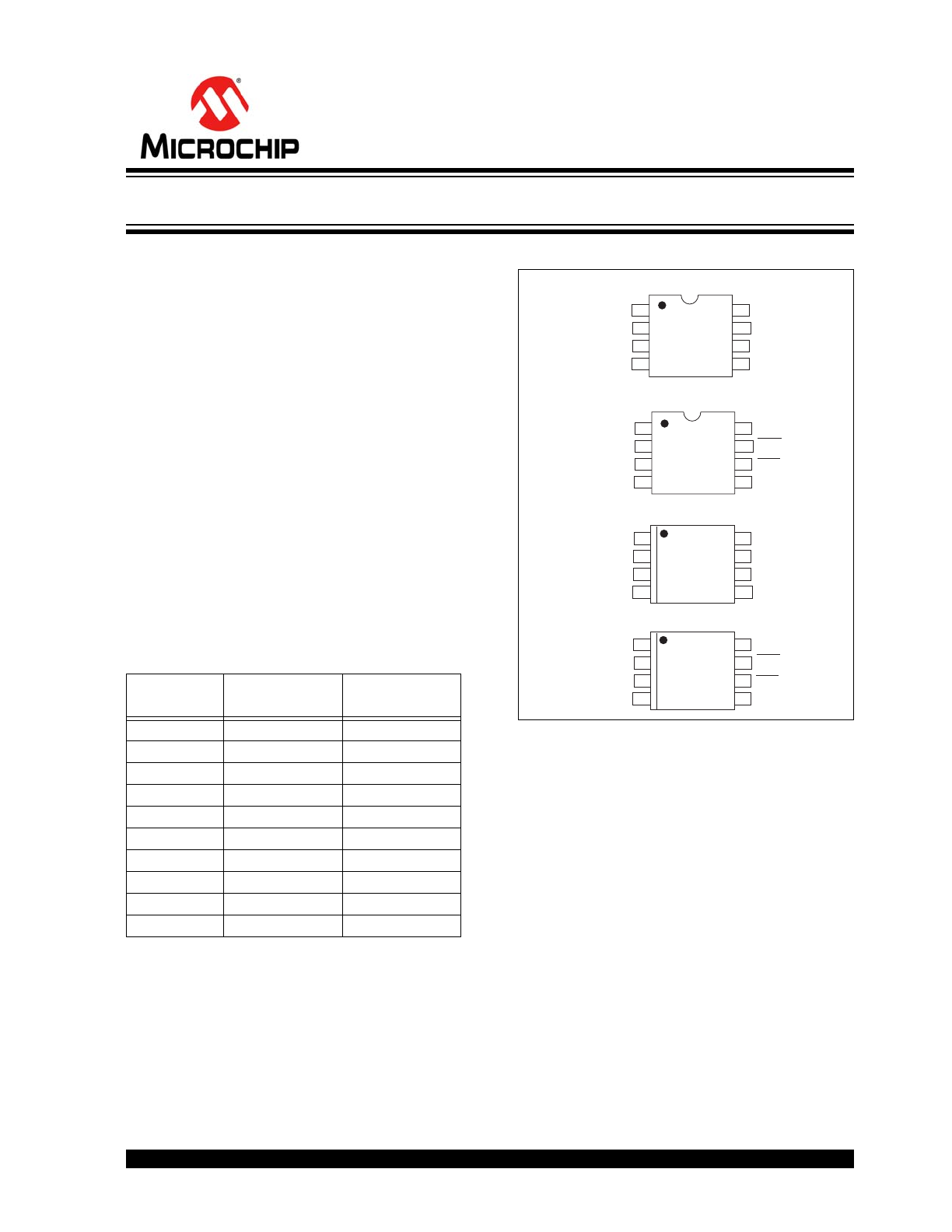
Package Type
General Description
The TC620 and TC621 are programmable logic output
temperature detectors designed for use in thermal
management applications. The TC620 features an
onboard temperature sensor, while the TC621
connects to an external NTC thermistor for remote
sensing applications.
Both devices feature dual thermal interrupt outputs
(HIGH LIMIT and LOW LIMIT), each of which is pro-
grammed with a single external resistor. On the TC620,
these outputs are driven active (high) when measured
temperature equals the user programmed limits. The
CONTROL (hysteresis) output is driven high when tem-
perature equals the high limit setting and returns low
when temperature falls below the low limit setting. This
output can be used to provide ON/OFF control to a
cooling fan or heater. The TC621 provides the same
output functions except that the logical states are
inverted.
The TC620/TC621 are usable over operating
temperature ranges of 0°C to 70°C, -40°C to +125°C.
Part Number
Package
Temperature
Range
TC620X*COA
8-Pin SOIC
0°C to +70°C
TC620X*CPA
8-Pin PDIP
0°C to +70°C
TC620X*EOA
8-Pin SOIC
-40°C to +85°C
TC620X*EPA
8-Pin PDIP
-40°C to +85°C
TC620C*VOA
8-Pin SOIC
-40°C to +125°C
TC621X*COA
8-Pin SOIC
0°C to +70°C
TC621X*CPA
8-Pin PDIP
0°C to +70°C
TC621X*EOA
8-Pin SOIC
-40°C to +85°C
TC621X*EPA
8-Pin PDIP
-40°C to +85°C
TC621C*VOA
8-Pin SOIC
-40°C to +125°C
THERMISTOR
8-SOIC
8-SOIC
VDD
GND
LOW LIMIT
CONTROL
NC
LOW SET
HIGH SET
HIGH LIMIT
VDD
GND
LOW LIMIT
CONTROL
LOW SET
HIGH SET
HIGH LIMIT
8
7
6
5
1
2
3
4
TC621XCOA
TC621XEOA
8
7
6
5
1
2
3
4
TC620XCOA
TC620XEOA
TC620CVOA
THERMISTOR
8-PDIP
VDD
GND
LOW LIMIT
CONTROL
LOW SET
HIGH SET
HIGH LIMIT
8
7
6
5
1
2
3
4
TC621XCPA
TC621XEPA
NC
8-PDIP
VDD
GND
LOW LIMIT
CONTROL
HIGH SET
LOW SET
HIGH LIMIT
8
7
6
5
1
2
3
4
TC620XCPA
TC620XEPA
5V, Dual Trip Point Temperature Sensors
TC620/TC621
DS20001439E-page 2
2001-2015 Microchip Technology Inc.
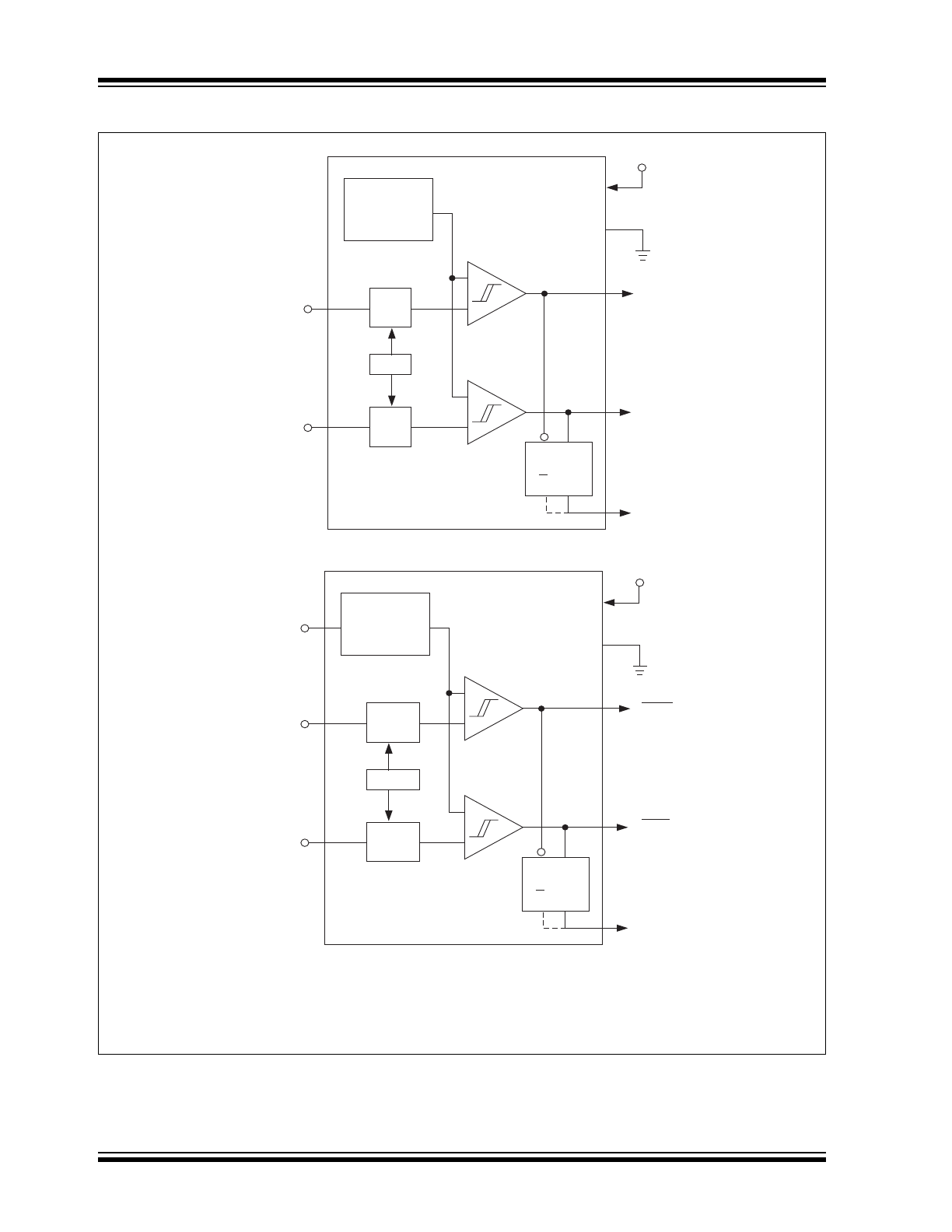
Functional Block Diagrams
3
HIGH SET
2
LOW SET
5
CONTROL*
6
HIGH LIMIT
VDD
7
LOW LIMIT
8
4
*Suffix code "C" denotes cooling option (High true CONTROL output).
Suffix code "H" denotes heating option (Low true CONTROL output).
Q
S
R
Q
+
+
–
–
TC620
HIGH SET
LOW SET
1
THERMISTOR
CONTROL*
HIGH LIMIT
LOW LIMIT
Temp. to
Voltage
Converter
VREF
GEN
VREF
GEN
VREF
3
2
5
6
VDD
7
8
4
Q
S
R
Q
+
+
–
–
TC621
Thermistor
Interface
Circuit
VREF
GEN
VREF
GEN
VREF
2001-2015 Microchip Technology Inc.
DS20001439E-page 3
TC620/TC621
1.0
ELECTRICAL
CHARACTERISTICS
Absolute Maximum Ratings*
Supply Voltage ....................................................... 20V
Input Voltage Any Input .. (GND – 0.3V) to (V
DD
+0.3V)
Package Power Dissipation (T
A
70°C)
PDIP ............................................. 730 mW
SOIC ............................................. 470 mW
Derating Factors:
Plastic .......................................... 8
mW/°C
Operating Temperature:
V Version ......................... -40°C to +125°C
E Version ........................... -40°C to +85°C
C Version .............................. 0°C to +70°C
Storage Temperature ......................... -65°C to +150°C
*Stresses above those listed under “Absolute Maxi-
mum Ratings” may cause permanent damage to the
device. These are stress ratings only and functional
operation of the device at these or any other conditions
above those indicated in the operation sections of the
specifications is not implied. Exposure to Absolute
Maximum Rating conditions for extended periods may
affect device reliability.
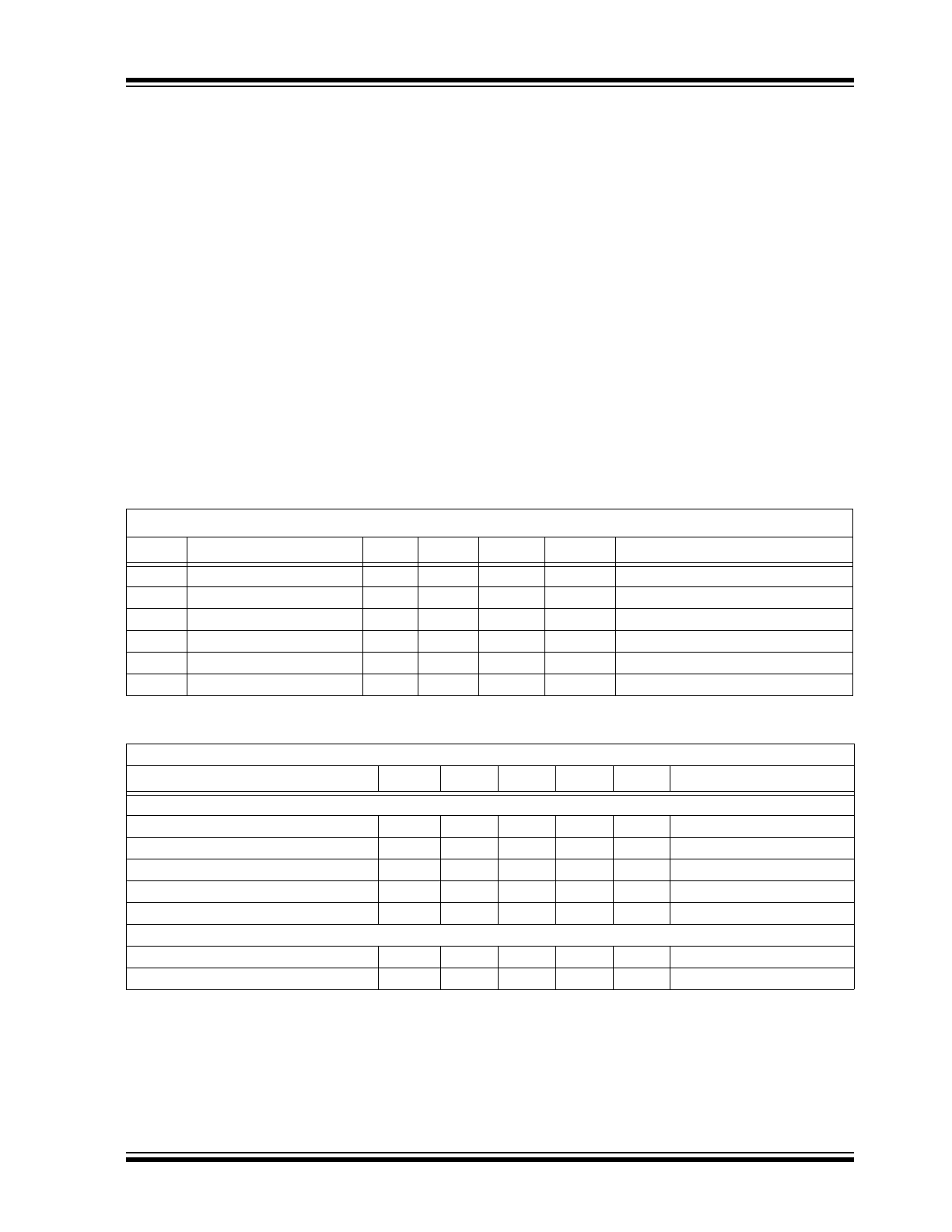
TC620/TC621 ELECTRICAL SPECIFICATIONS
TEMPERATURE CHARACTERISTICS
Electrical Characteristics: T
A
= 25°C, unless otherwise specified.
Symbol
Parameter
Min.
Typ.
Max.
Unit
Test Conditions
V
DD
Supply Voltage Range
4.5
—
18
V
I
DD
Supply Current
—
270
400
A
5V
V
DD
18V
R
OUT
Output Resistance
—
400
1000
W
Output High or Low, 5V
V
DD
18V
I
OUT
Output Current
—
—
1
mA
Temp. Sensed Source/Sink
I
OUT
Output Current
—
—
1
mA
Cool/Heat Source/Sink
T
ERR
Absolute Accuracy
T - 3
T
T + 3
°C
T = Programmed Temperature
Electrical Specifications: Unless otherwise noted, all parameters apply with 4.5V
V
DD
18V.
Parameters
Sym.
Min.
Typ.
Max.
Units
Conditions
Temperature Ranges
Specified Temperature Range (C)
T
A
0
—
+70
°C
Specified Temperature Range (E)
T
A
-40
—
+85
°C
Specified Temperature Range (V)
T
A
-40
—
+125
°C
Maximum Junction Temperature
T
J
—
—
+150
°C
Storage Temperature Range
T
A
-65
—
+150
°C
Package Thermal Resistances
Thermal Resistance, 8L-PDIP
JA
—
125
—
°C/W
Thermal Resistance, 8L-SOIC
JA
—
155
—
°C/W
TC620/TC621
DS20001439E-page 4
2001-2015 Microchip Technology Inc.
2.0
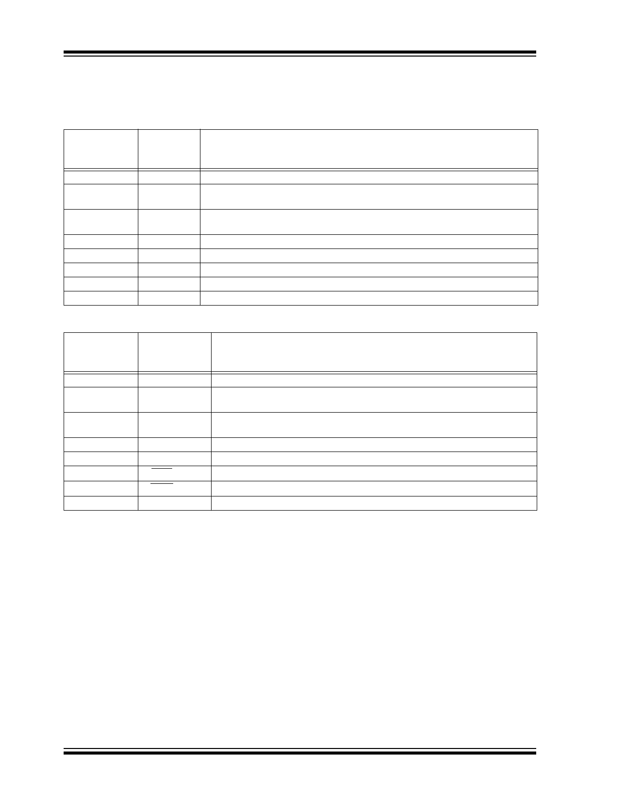
PIN DESCRIPTIONS
The descriptions of the pins are listed in
Table 2-1
.
TABLE 2-1:
TC620 PIN FUNCTION TABLE
TABLE 2-2:
TC621 PIN FUNCTION TABLE
Pin No.
(8-Pin PDIP)
(8-Pin SOIC)
Symbol
Description
1
NC
No Internal Connection.
2
LOW SET
Low temperature set point. Connect an external 1% resistor from LOW SET to V
DD
to set trip point.
3
HIGH SET
High temperature set point. Connect an external 1% resistor from HIGH SET to
V
DD
to set trip point.
4
GND
Ground Terminal.
5
CONTROL
Control output.
6
HIGH LIMIT
High temperature push/pull output.
7
LOW LIMIT
Low temperature push/pull output.
8
V
DD
Power supply input.
Pin No.
(8-Pin PDIP)
(8-Pin SOIC)
Symbol
Description
1
THERMISTOR
Thermistor input.
2
HIGH SET
High temperature set point. Connect an external 1% resistor from HIGH SET to
V
DD
to set trip point.
3
LOW SET
Low temperature set point. Connect an external 1% resistor from LOW SET to
V
DD
to set trip point.
4
GND
Ground Terminal.
5
CONTROL
Control output.
6
LOW LIMIT
Low temperature push/pull output.
7
HIGH LIMIT
High temperature push/pull output.
8
V
DD
Power supply input.
2001-2015 Microchip Technology Inc.
DS20001439E-page 5
TC620/TC621
3.0
DETAILED DESCRIPTION
The TC620 has a positive temperature coefficient tem-
perature sensor and a dual threshold detector. Tem-
perature set point programming is accomplished with
external resistors from the HIGH SET and LOW SET
inputs to V
DD.
The HIGH LIMIT and LOW LIMIT outputs
remain low as long as measured temperature is below
set point values. As measured temperature increases,
the LOW LIMIT output is driven high when temperature
equals the LOW SET set point (±3°C max). If tempera-
ture continues to climb, the HIGH LIMIT output is driven
high when temperature equals the HIGH SET set point
(
Figure 3-1
). The CONTROL (hysteresis) output is
latched in its active state at the temperature specified
by the HIGH SET resistor. CONTROL is maintained
active until temperature falls to the value specified by
the LOW SET resistor.
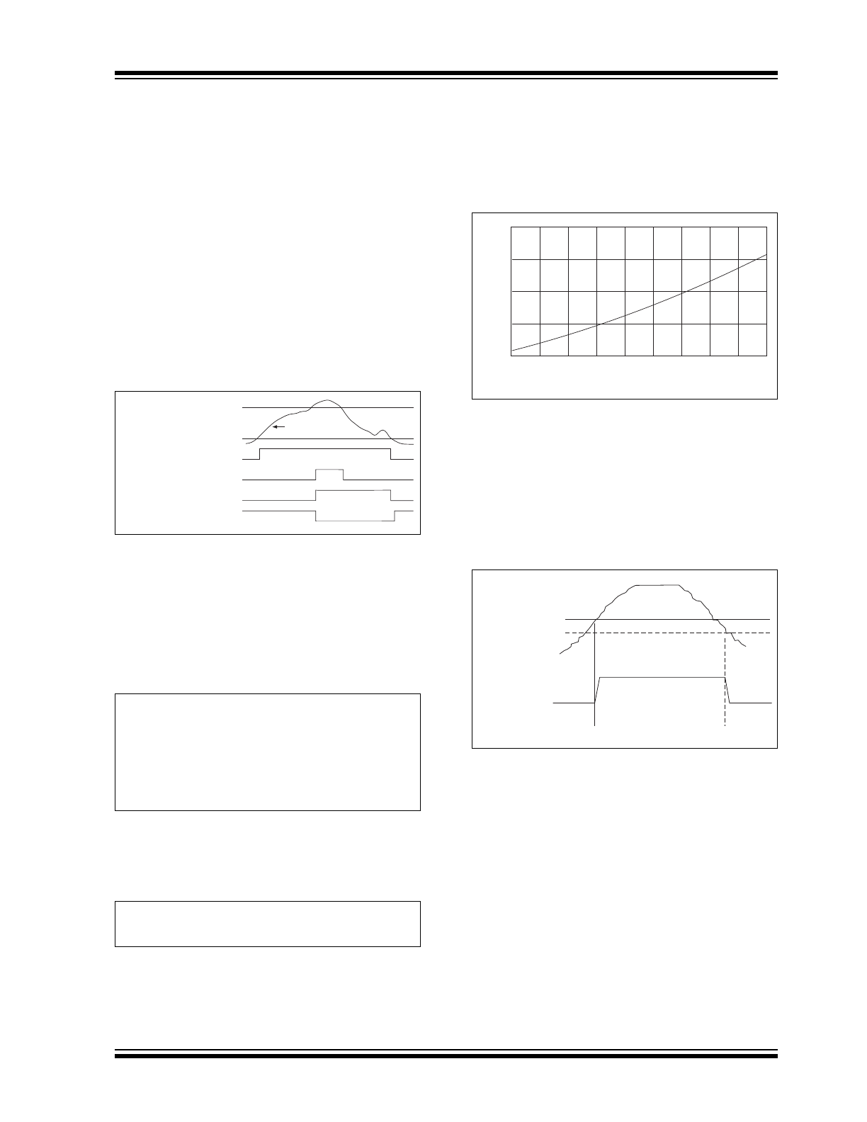
FIGURE 3-1:
TC620/TC621 Input vs.
Output Logic.
3.1
Programming the TC620
The resistor values to achieve the desired trip point
temperatures on HIGH SET and LOW SET are
calculated using
Equation 3-1
:
EQUATION 3-1:
For example, a 50°C setting on either the HIGH SET
or LOW SET input is calculated using
Equation 3-2
as
follows:
EQUATION 3-2:
Care must be taken to ensure the LOW SET program-
ming resistor is a smaller value than the HIGH SET
programming resistor. Failure to do this will result in
erroneous operation of the CONTROL output.
Care must also be taken to ensure the LOW SET
temperature setting is at least 5°C lower than the HIGH
SET temperature setting.
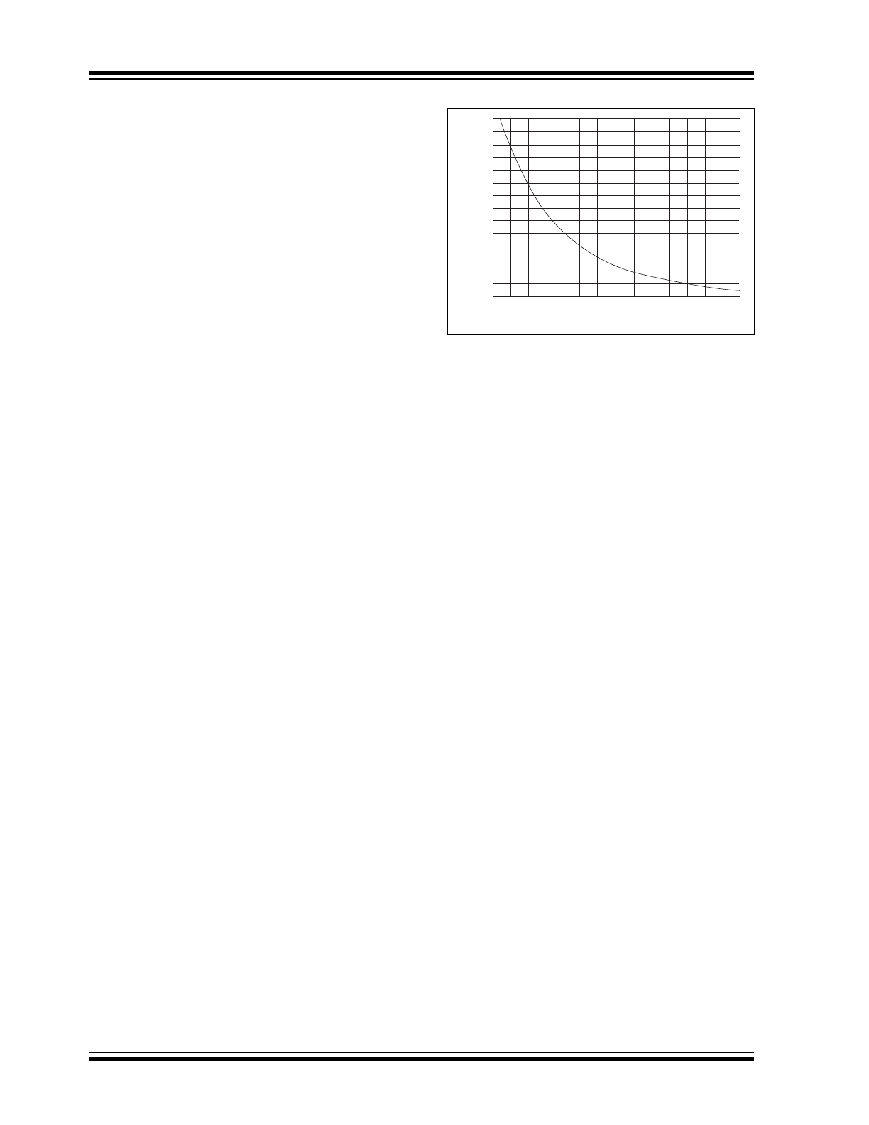
Figure 3-2
can help the user obtain an estimate of the
external resistor values required for the desired LOW
SET and HIGH SET trip points.
FIGURE 3-2:
TC620 Sense Resistors vs.
Trip Temperature.
3.2
Built-in Hysteresis
To prevent output “chattering” when measured
temperature is at (or near) the programmed trip point
values, the LOW SET and HIGH SET inputs each have
built-in hysteresis of -2°C below the programmed
settings (
Figure 3-3
).
FIGURE 3-3:
Built-In Hysteresis on Low
Limit and High Limit Outputs.
As shown, the outputs remain in their active state
(hysteresis) until temperature falls an additional 2°C
below the user’s setting.
Low Set Point
High Set Point
Low Limit Output
High Limit Output
Control Output (Cool Option
Control Output (Heat Option)
Temperature
R
TRIP
= 0.5997 x T
2.1312
Where:
R
TRIP
= Programming resistor in Ohms
T = The desired trip point temperature in degrees
Kelvin.
R
SET
= 0.5997 x ((50 + 273.15)
2.1312
) = 133.6 k
TEMPERATURE
(°C)
RESISTANCE, R
TRIP
(k
Ω
)
-55
-35
-15
5
25
45
65
85
105
125
50
100
150
200
250
Set Point
(Set Point 2°C)
High Limit
or Low Limit
Output
TC620/TC621
DS20001439E-page 6
2001-2015 Microchip Technology Inc.
3.3
Using the TC621
The TC621 operation is similar to that of the TC620, but
requires an external NTC thermistor. Use the resis-
tance versus temperature curve of the thermistor to
determine the values of the programming resistors.
Note that the pin numbers for the HIGH SET and LOW
SET programming resistors for the TC621 are reversed
versus that of the TC620 (i.e., the resistor value on
HIGH SET [Pin 2] should always be lower than the one
connected to LOW SET [Pin 3]). Also note that the
outputs of the TC621 are LOW TRUE when used with
an NTC thermistor.
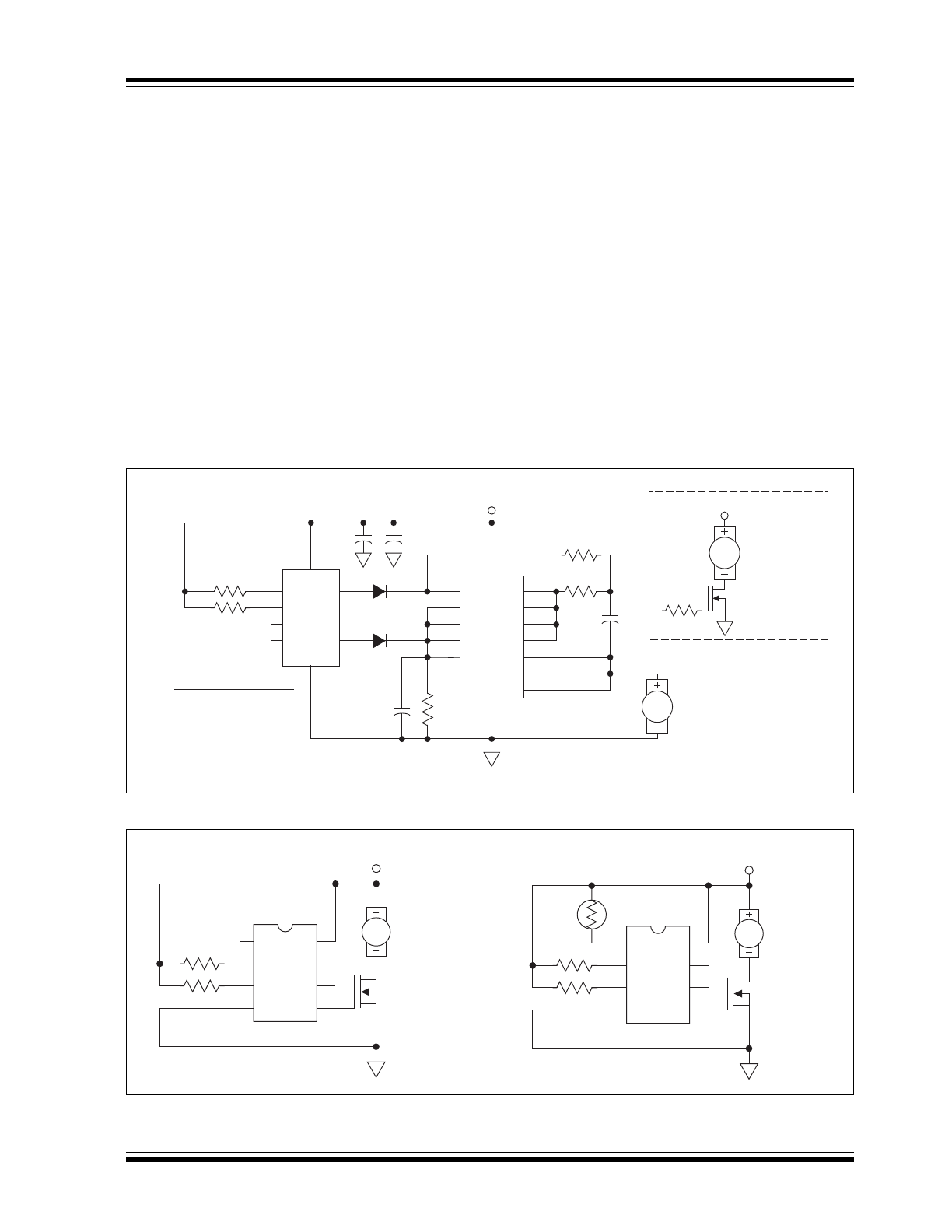
3.4
TC621 Thermistor Selection
The TC621 uses an external thermistor to monitor the
controlling temperature. A thermistor with a resistance
value of approximately 100 k
at 25°C is
recommended.
A temperature set point is selected by picking a resis-
tor whose value is equal to the resistance of the therm-
istor at the desired temperature. For example, using
the data shown in
Figure 3-4
, a 30 k
resistor between
HIGH TEMP (Pin 2) and V
DD
(Pin 8) sets the high
temperature trip point at +51°C and a 49 k
resistor on
LOW TEMP (Pin 3) sets the low temperature trip point
to +41°C.
FIGURE 3-4:
Typical NTC Thermistor.
3.5
TC620/TC621 Outputs
Both devices have complimentary output stages. They
are rated at a source or sink current of 1 mA maximum.
0
10
20
30
40
50
100
70
TEMPERATURE (°C)
0
50
60
150
200
250
300
350
THERMISTOR RESISTANCE (k
Ω
)
2001-2015 Microchip Technology Inc.
DS20001439E-page 7
TC620/TC621
4.0
TYPICAL APPLICATIONS
4.1
Dual Speed Temperature Control
In
Figure 4-1
, the Dual Speed Temperature Control
uses a TC620 and a TC4469 quad driver. Two of the
drivers of the TC4469 are configured in a simple oscil-
lator. When the temperature is below the LOW TEMP
set point, the output of the driver is OFF. When the tem-
perature exceeds the LOW TEMP set point, the
TC4469 gates the oscillator signal to the outputs of the
driver. This square wave signal modulates the remain-
ing outputs and drives the motor at a low speed. If this
speed cannot keep the temperature below the HIGH
TEMP set point, then the driver turns on continuously
which increases the fan speed to high. The TC620 will
monitor the temperature and only allow the fan to oper-
ate when needed and at the required speed to maintain
the desired temperature. A higher power option can be
designed by adding a resistor and a power MOSFET.
4.2
Temperature Controlled Fan
In the application in
Figure 4-2
, a high and a low tem-
perature is selected by two R
L
and R
H
. The TC620
monitors the ambient temperature and turns the FET
switch on when the temperature exceeds the HIGH
TEMP set point. The fan remains on until the tempera-
ture decreases to the LOW TEMP set point. This
provides the hysteresis. In this application, the fan
turns on only when required.
The TC621 uses an external thermistor to monitor the
ambient temperature. This adds one part, but allows
more flexibility with the location of the temperature
sensor.
FIGURE 4-1:
Dual Speed Temperature Control.
FIGURE 4-2:
Temperature Controlled Fan.
TC620
2
3
1
5
6
7
+12V
VMOTOR
MOSFET
Fan Motor
50
Ω
Higher Power Option
1N4148
1N4148
8
4
TC4469
2
1
3
5
8
13
4
6
9
10
11
12
14
1M
10k
100k
High
Limit
Low
Limit
Fan Motor
50 pF
Temperature Scale
7
Low Temp.
30 C
˚
High Temp.
50 C
˚
10 µF
0.1 µF
– 30 C (Fan Off)
– 50 C (Fan Low)
– UP (Fan High)
˚
˚
1 µF
0 C
30 C
50 C
˚
˚
˚
TC620
High Temp.
1
2
3
4
8
7
6
5
Low Temp.
+12V
MTP3055E
Fan Motor
TC621
High
Temp.
1
2
3
4
8
7
6
5
Low Temp.
+12V
MTP3055E
Fan Motor
Thermistor
(NTC)
R
L
R
L
R
H
R
H
TC620/TC621
DS20001439E-page 8
2001-2015 Microchip Technology Inc.
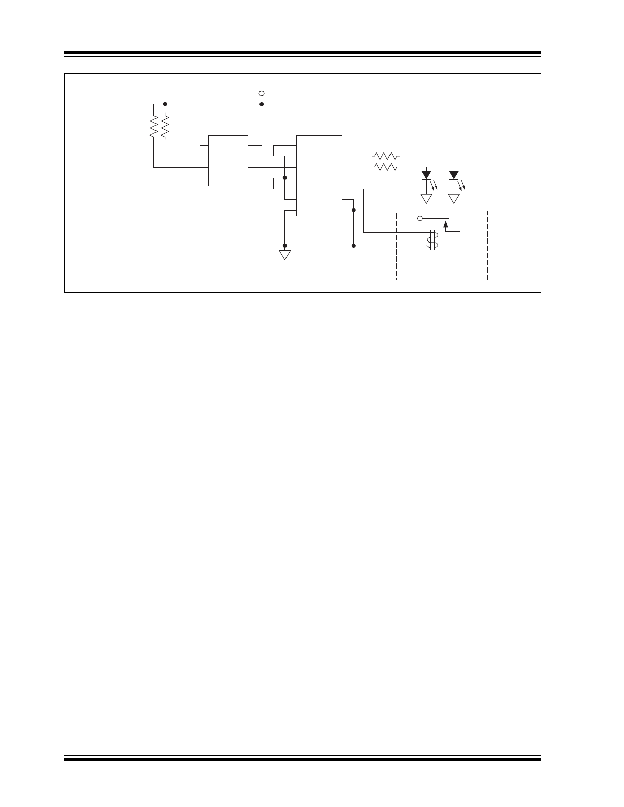
FIGURE 4-3:
Heating and Cooling Application.
TC620
1
2
3
4
8
7
6
5
TC4469
1
2
3
4
5
6
7
14
13
12
11
10
9
8
High
Temp.
Warning
Heating/Cooling
Equipment
1k
1k
Low
Temp.
Warning
4.5V to 18V
High
Temp.
Low
Temp.
2001-2015 Microchip Technology Inc.
DS20001439E-page 9
TC620/TC621
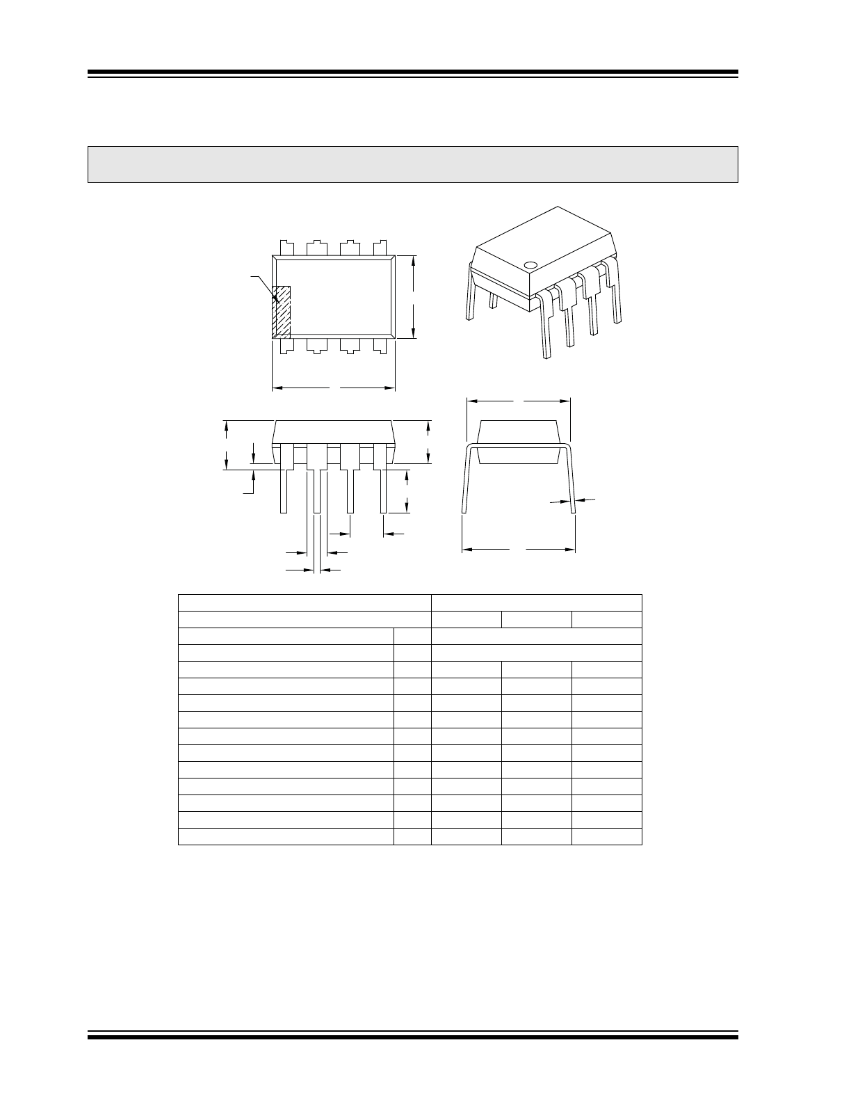
5.0
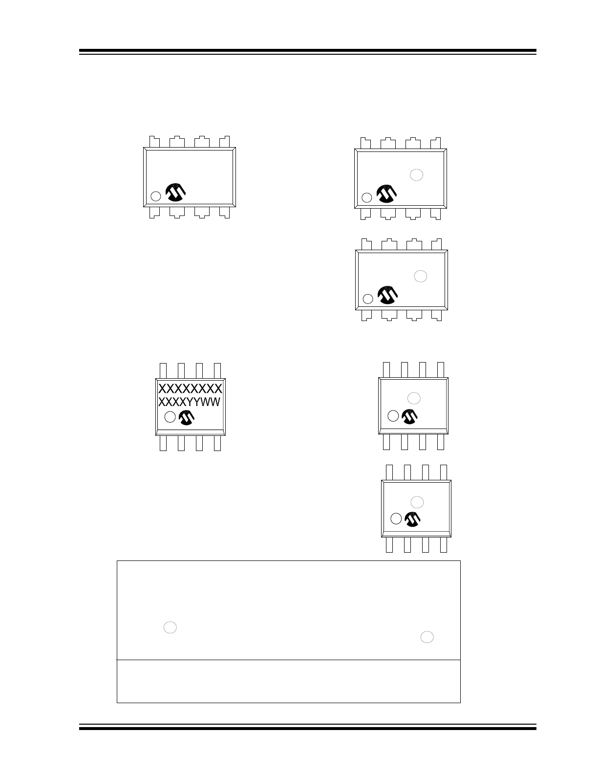
PACKAGING INFORMATION
5.1
Package Marking Information
XXXXXXXX
XXXXXNNN
YYWW
NNN
8-Lead PDIP (300 mil)
8-Lead SOIC (150 mil)
Example
Example
TC620C
CPA ^^ 256
1503
TC621C
CPA ^^ 256
1503
TC620HC
OA ^^ 1503
256
TC621HE
OA ^^ 1503
256
3
e
3
e
3
e
3
e
Legend: XX...X
Customer-specific information
Y
Year code (last digit of calendar year)
YY
Year code (last 2 digits of calendar year)
WW
Week code (week of January 1 is week ‘01’)
NNN
Alphanumeric traceability code
Pb-free JEDEC
®
designator for Matte Tin (Sn)
*
This package is Pb-free. The Pb-free JEDEC designator ( )
can be found on the outer packaging for this package.
Note:
In the event the full Microchip part number cannot be marked on one line, it will
be carried over to the next line, thus limiting the number of available
characters for customer-specific information.
3
e
3
e
TC620/TC621
DS20001439E-page 10
2001-2015 Microchip Technology Inc.
!
!"#$
%&
'#
*!+,#'*#"',
'
$.''
'
$
/&'1' "'
2 * ""$4$'#$ *$&" '#""$&" '#"""' % $5 "$
* "$' 467
91:9"* " ' %'!# "..'#'' "
!
;'
*"'#
'
<
$."+
"
"
'
<
&''
$'
''
:==...*
*=
<
>'"
?1@4
* "A*'"
?
?B
C
?#*, &"
?
F
'
91
' '
G
G
$ $< < ""
7
2
7
9" ' '
7
G
G
#$ '#$ H$'
4
2
27
$ $< H$'
4
7
F
B! A '
2F
27
' '
A
7
2
7
A $< ""
F
7
> A $H$'
,
A. A $H$'
,
F
B! . /
9
G
G
2
N
E1
NOTE 1
D
1
2
3
A
A1
A2
L
b1
b
e
E
eB
c
. 1 F9