

SMSC LAN8742A/LAN8742Ai
Revision 1.1 (05-21-13)
DATASHEET
Datasheet
PRODUCT FEATURES
LAN8742A/LAN8742Ai
Small Footprint RMII 10/100 Ethernet
Transceiver with HP Auto-MDIX and
flexPWR
®
Technology
Highlights
Single-Chip Ethernet Physical Layer Transceiver
(PHY)
Cable diagnostic support
Wake on LAN (WoL) support
Comprehensive flexPWR
®
technology
— Flexible power management architecture
— LVCMOS Variable I/O voltage range: +1.8 V to +3.3 V
— Integrated 1.2 V regulator with disable feature
HP Auto-MDIX support
Miniature 24-pin SQFN, RoHS-compliant package
(4 x 4 x 0.9 mm height)
Target Applications
Set-Top Boxes
Networked Printers and Servers
Test Instrumentation
LAN on Motherboard
Embedded Telecom Applications
Video Record/Playback Systems
Cable Modems/Routers
DSL Modems/Routers
Digital Video Recorders
IP and Video Phones
Wireless Access Points
Digital Televisions
Digital Media Adaptors/Servers
Gaming Consoles
POE Applications
(Refer to SMSC Application Note 17.18)
Key Benefits
High-performance 10/100 Ethernet transceiver
— Compliant with IEEE802.3/802.3u (Fast Ethernet)
— Compliant with ISO 802-3/IEEE 802.3 (10BASE-T)
— Loop-back modes
— Auto-negotiation
— Automatic polarity detection and correction
— Link status change wake-up detection
— Vendor specific register functions
— Supports the reduced pin count RMII interface
Power and I/Os
— Various low power modes
— Integrated power-on reset circuit
— Two status LED outputs
— May be used with a single 3.3 V supply
Additional Features
— Ability to use a low cost 25 MHz crystal for reduced
BOM
Packaging
— 24-pin SQFN (4 x 4 mm), RoHS-compliant package with
RMII
Environmental
— Commercial temperature range (0°C to +70°C)
— Industrial temperature range (-40°C to +85°C)

ORDER NUMBER(S):
LAN8742A-CZ (Tray) for 24-pin, SQFN, RoHS-compliant package (0°C to +70°C temp)
LAN8742Ai-CZ (Tray) for 24-pin, SQFN, RoHS-compliant package (-40°C to +85°C temp)
LAN8742A-CZ-TR (Tape & Reel) for 24-pin, SQFN, RoHS-compliant package (0°C to +70°C temp)
LAN8742Ai-CZ-TR (Tape & Reel) for 24-pin, SQFN, RoHS-compliant package (-40 to +85°C temp)
This product meets the halogen maximum concentration values per IEC61249-2-21.
For RoHS compliance and environmental information, please visit
Please contact your SMSC sales representative for additional documentation related to this product
such as application notes, anomaly sheets, and design guidelines.
Revision 1.1 (05-21-13)
2
SMSC LAN8742A/LAN8742Ai
DATASHEET
Copyright © 2013 SMSC or its subsidiaries. All rights reserved.
Circuit diagrams and other information relating to SMSC products are included as a means of illustrating typical applications. Consequently, complete information sufficient for
construction purposes is not necessarily given. Although the information has been checked and is believed to be accurate, no responsibility is assumed for inaccuracies. SMSC
reserves the right to make changes to specifications and product descriptions at any time without notice. Contact your local SMSC sales office to obtain the latest specifications
before placing your product order. The provision of this information does not convey to the purchaser of the described semiconductor devices any licenses under any patent
rights or other intellectual property rights of SMSC or others. All sales are expressly conditional on your agreement to the terms and conditions of the most recently dated
version of SMSC's standard Terms of Sale Agreement dated before the date of your order (the "Terms of Sale Agreement"). The product may contain design defects or errors
known as anomalies which may cause the product's functions to deviate from published specifications. Anomaly sheets are available upon request. SMSC products are not
designed, intended, authorized or warranted for use in any life support or other application where product failure could cause or contribute to personal injury or severe property
damage. Any and all such uses without prior written approval of an Officer of SMSC and further testing and/or modification will be fully at the risk of the customer. Copies of
this document or other SMSC literature, as well as the Terms of Sale Agreement, may be obtained by visiting SMSC’s website at http://www.smsc.com. SMSC is a registered
trademark of Standard Microsystems Corporation (“SMSC”). Product names and company names are the trademarks of their respective holders.
The Microchip name and logo, and the Microchip logo are registered trademarks of Microchip Technology Incorporated in the U.S.A. and other countries.
SMSC DISCLAIMS AND EXCLUDES ANY AND ALL WARRANTIES, INCLUDING WITHOUT LIMITATION ANY AND ALL IMPLIED WARRANTIES OF MERCHANTABILITY,
FITNESS FOR A PARTICULAR PURPOSE, TITLE, AND AGAINST INFRINGEMENT AND THE LIKE, AND ANY AND ALL WARRANTIES ARISING FROM ANY COURSE
OF DEALING OR USAGE OF TRADE. IN NO EVENT SHALL SMSC BE LIABLE FOR ANY DIRECT, INCIDENTAL, INDIRECT, SPECIAL, PUNITIVE, OR CONSEQUENTIAL
DAMAGES; OR FOR LOST DATA, PROFITS, SAVINGS OR REVENUES OF ANY KIND; REGARDLESS OF THE FORM OF ACTION, WHETHER BASED ON CONTRACT;
TORT; NEGLIGENCE OF SMSC OR OTHERS; STRICT LIABILITY; BREACH OF WARRANTY; OR OTHERWISE; WHETHER OR NOT ANY REMEDY OF BUYER IS HELD
TO HAVE FAILED OF ITS ESSENTIAL PURPOSE, AND WHETHER OR NOT SMSC HAS BEEN ADVISED OF THE POSSIBILITY OF SUCH DAMAGES.
Small Footprint RMII 10/100 Ethernet Transceiver with HP Auto-MDIX and flexPWR
®
Technology
Datasheet

Small Footprint RMII 10/100 Ethernet Transceiver with HP Auto-MDIX and flexPWR
®
Technology
Datasheet
SMSC LAN8742A/LAN8742Ai
3
Revision 1.1 (05-21-13)
DATASHEET
Table of Contents
Chapter 1 Introduction . . . . . . . . . . . . . . . . . . . . . . . . . . . . . . . . . . . . . . . . . . . . . . . . . . . . . . . 8
1.1
General Terms and Conventions . . . . . . . . . . . . . . . . . . . . . . . . . . . . . . . . . . . . . . . . . . . . . . . . . . . 8
1.2
General Description . . . . . . . . . . . . . . . . . . . . . . . . . . . . . . . . . . . . . . . . . . . . . . . . . . . . . . . . . . . . . 8
Chapter 2 Pin Description and Configuration . . . . . . . . . . . . . . . . . . . . . . . . . . . . . . . . . . . 10
2.1
Pin Assignments . . . . . . . . . . . . . . . . . . . . . . . . . . . . . . . . . . . . . . . . . . . . . . . . . . . . . . . . . . . . . . . 18
2.2
Buffer Types . . . . . . . . . . . . . . . . . . . . . . . . . . . . . . . . . . . . . . . . . . . . . . . . . . . . . . . . . . . . . . . . . . 19
Chapter 3 Functional Description . . . . . . . . . . . . . . . . . . . . . . . . . . . . . . . . . . . . . . . . . . . . . 20
3.1
Transceiver . . . . . . . . . . . . . . . . . . . . . . . . . . . . . . . . . . . . . . . . . . . . . . . . . . . . . . . . . . . . . . . . . . . 20
3.1.1
100BASE-TX Transmit . . . . . . . . . . . . . . . . . . . . . . . . . . . . . . . . . . . . . . . . . . . . . . . . . . 20
3.1.2
100BASE-TX Receive . . . . . . . . . . . . . . . . . . . . . . . . . . . . . . . . . . . . . . . . . . . . . . . . . . . 23
3.1.3
10BASE-T Transmit. . . . . . . . . . . . . . . . . . . . . . . . . . . . . . . . . . . . . . . . . . . . . . . . . . . . . 25
3.1.4
10BASE-T Receive . . . . . . . . . . . . . . . . . . . . . . . . . . . . . . . . . . . . . . . . . . . . . . . . . . . . . 26
3.2
Auto-Negotiation . . . . . . . . . . . . . . . . . . . . . . . . . . . . . . . . . . . . . . . . . . . . . . . . . . . . . . . . . . . . . . . 27
3.2.1
Parallel Detection . . . . . . . . . . . . . . . . . . . . . . . . . . . . . . . . . . . . . . . . . . . . . . . . . . . . . . 28
3.2.2
Restarting Auto-Negotiation . . . . . . . . . . . . . . . . . . . . . . . . . . . . . . . . . . . . . . . . . . . . . . 28
3.2.3
Disabling Auto-Negotiation . . . . . . . . . . . . . . . . . . . . . . . . . . . . . . . . . . . . . . . . . . . . . . . 29
3.2.4
Half vs. Full Duplex . . . . . . . . . . . . . . . . . . . . . . . . . . . . . . . . . . . . . . . . . . . . . . . . . . . . . 29
3.3
HP Auto-MDIX Support. . . . . . . . . . . . . . . . . . . . . . . . . . . . . . . . . . . . . . . . . . . . . . . . . . . . . . . . . . 29
3.4
MAC Interface. . . . . . . . . . . . . . . . . . . . . . . . . . . . . . . . . . . . . . . . . . . . . . . . . . . . . . . . . . . . . . . . . 30
3.4.1
RMII . . . . . . . . . . . . . . . . . . . . . . . . . . . . . . . . . . . . . . . . . . . . . . . . . . . . . . . . . . . . . . . . . 30
3.5
Serial Management Interface (SMI) . . . . . . . . . . . . . . . . . . . . . . . . . . . . . . . . . . . . . . . . . . . . . . . . 31
3.6
Interrupt Management . . . . . . . . . . . . . . . . . . . . . . . . . . . . . . . . . . . . . . . . . . . . . . . . . . . . . . . . . . 32
3.6.1
Primary Interrupt System . . . . . . . . . . . . . . . . . . . . . . . . . . . . . . . . . . . . . . . . . . . . . . . . . 33
3.6.2
Alternate Interrupt System . . . . . . . . . . . . . . . . . . . . . . . . . . . . . . . . . . . . . . . . . . . . . . . . 34
3.7
Configuration Straps . . . . . . . . . . . . . . . . . . . . . . . . . . . . . . . . . . . . . . . . . . . . . . . . . . . . . . . . . . . . 35
3.7.1
PHYAD[0]: PHY Address Configuration . . . . . . . . . . . . . . . . . . . . . . . . . . . . . . . . . . . . . 35
3.7.2
MODE[2:0]: Mode Configuration . . . . . . . . . . . . . . . . . . . . . . . . . . . . . . . . . . . . . . . . . . . 36
3.7.3
REGOFF: Internal +1.2 V Regulator Configuration . . . . . . . . . . . . . . . . . . . . . . . . . . . . . 37
3.7.4
nINTSEL: nINT/REFCLKO Configuration . . . . . . . . . . . . . . . . . . . . . . . . . . . . . . . . . . . . 38
3.8
Miscellaneous Functions . . . . . . . . . . . . . . . . . . . . . . . . . . . . . . . . . . . . . . . . . . . . . . . . . . . . . . . . 42
3.8.1
LEDs . . . . . . . . . . . . . . . . . . . . . . . . . . . . . . . . . . . . . . . . . . . . . . . . . . . . . . . . . . . . . . . . 42
3.8.2
Variable Voltage I/O . . . . . . . . . . . . . . . . . . . . . . . . . . . . . . . . . . . . . . . . . . . . . . . . . . . . 46
3.8.3
Power-Down Modes . . . . . . . . . . . . . . . . . . . . . . . . . . . . . . . . . . . . . . . . . . . . . . . . . . . . 46
3.8.4
Wake on LAN (WoL) . . . . . . . . . . . . . . . . . . . . . . . . . . . . . . . . . . . . . . . . . . . . . . . . . . . . 47
3.8.5
Isolate Mode . . . . . . . . . . . . . . . . . . . . . . . . . . . . . . . . . . . . . . . . . . . . . . . . . . . . . . . . . . 52
3.8.6
Resets . . . . . . . . . . . . . . . . . . . . . . . . . . . . . . . . . . . . . . . . . . . . . . . . . . . . . . . . . . . . . . . 52
3.8.7
Carrier Sense . . . . . . . . . . . . . . . . . . . . . . . . . . . . . . . . . . . . . . . . . . . . . . . . . . . . . . . . . 53
3.8.8
Link Integrity Test . . . . . . . . . . . . . . . . . . . . . . . . . . . . . . . . . . . . . . . . . . . . . . . . . . . . . . 53
3.8.9
Cable Diagnostics . . . . . . . . . . . . . . . . . . . . . . . . . . . . . . . . . . . . . . . . . . . . . . . . . . . . . . 53
3.8.10
Loopback Operation . . . . . . . . . . . . . . . . . . . . . . . . . . . . . . . . . . . . . . . . . . . . . . . . . . . . 58
3.9
Application Diagrams . . . . . . . . . . . . . . . . . . . . . . . . . . . . . . . . . . . . . . . . . . . . . . . . . . . . . . . . . . . 60
3.9.1
Simplified System Level Application Diagram . . . . . . . . . . . . . . . . . . . . . . . . . . . . . . . . 60
3.9.2
Power Supply Diagram (1.2 V Supplied by Internal Regulator). . . . . . . . . . . . . . . . . . . . 61
3.9.3
Power Supply Diagram (1.2 V Supplied by External Source) . . . . . . . . . . . . . . . . . . . . . 62
3.9.4
Twisted-Pair Interface Diagram (Single Power Supply). . . . . . . . . . . . . . . . . . . . . . . . . . 63
3.9.5
Twisted-Pair Interface Diagram (Dual Power Supplies) . . . . . . . . . . . . . . . . . . . . . . . . . 64

Small Footprint RMII 10/100 Ethernet Transceiver with HP Auto-MDIX and flexPWR
®
Technology
Datasheet
Revision 1.1 (05-21-13)
4
SMSC LAN8742A/LAN8742Ai
DATASHEET
Chapter 4 Register Descriptions. . . . . . . . . . . . . . . . . . . . . . . . . . . . . . . . . . . . . . . . . . . . . . . 65
4.1
Register Nomenclature . . . . . . . . . . . . . . . . . . . . . . . . . . . . . . . . . . . . . . . . . . . . . . . . . . . . . . . . . . 65
4.2
Control and Status Registers . . . . . . . . . . . . . . . . . . . . . . . . . . . . . . . . . . . . . . . . . . . . . . . . . . . . . 66
4.2.1
Basic Control Register . . . . . . . . . . . . . . . . . . . . . . . . . . . . . . . . . . . . . . . . . . . . . . . . . . . 67
4.2.2
Basic Status Register . . . . . . . . . . . . . . . . . . . . . . . . . . . . . . . . . . . . . . . . . . . . . . . . . . . 68
4.2.3
PHY Identifier 1 Register . . . . . . . . . . . . . . . . . . . . . . . . . . . . . . . . . . . . . . . . . . . . . . . . . 70
4.2.4
PHY Identifier 2 Register . . . . . . . . . . . . . . . . . . . . . . . . . . . . . . . . . . . . . . . . . . . . . . . . . 71
4.2.5
Auto Negotiation Advertisement Register . . . . . . . . . . . . . . . . . . . . . . . . . . . . . . . . . . . . 72
4.2.6
Auto Negotiation Link Partner Ability Register. . . . . . . . . . . . . . . . . . . . . . . . . . . . . . . . . 73
4.2.7
Auto Negotiation Expansion Register . . . . . . . . . . . . . . . . . . . . . . . . . . . . . . . . . . . . . . . 74
4.2.8
Auto Negotiation Next Page TX Register . . . . . . . . . . . . . . . . . . . . . . . . . . . . . . . . . . . . 75
4.2.9
Auto Negotiation Next Page RX Register . . . . . . . . . . . . . . . . . . . . . . . . . . . . . . . . . . . . 76
4.2.10
MMD Access Control Register. . . . . . . . . . . . . . . . . . . . . . . . . . . . . . . . . . . . . . . . . . . . . 77
4.2.11
MMD Access Address/Data Register . . . . . . . . . . . . . . . . . . . . . . . . . . . . . . . . . . . . . . . 78
4.2.12
EDPD NLP / Crossover Time Register . . . . . . . . . . . . . . . . . . . . . . . . . . . . . . . . . . . . . . 79
4.2.13
Mode Control/Status Register . . . . . . . . . . . . . . . . . . . . . . . . . . . . . . . . . . . . . . . . . . . . . 80
4.2.14
Special Modes Register. . . . . . . . . . . . . . . . . . . . . . . . . . . . . . . . . . . . . . . . . . . . . . . . . . 81
4.2.15
TDR Patterns/Delay Control Register . . . . . . . . . . . . . . . . . . . . . . . . . . . . . . . . . . . . . . . 82
4.2.16
TDR Control/Status Register . . . . . . . . . . . . . . . . . . . . . . . . . . . . . . . . . . . . . . . . . . . . . . 83
4.2.17
Symbol Error Counter Register . . . . . . . . . . . . . . . . . . . . . . . . . . . . . . . . . . . . . . . . . . . . 84
4.2.18
Special Control/Status Indications Register. . . . . . . . . . . . . . . . . . . . . . . . . . . . . . . . . . . 85
4.2.19
Cable Length Register. . . . . . . . . . . . . . . . . . . . . . . . . . . . . . . . . . . . . . . . . . . . . . . . . . . 86
4.2.20
Interrupt Source Flag Register . . . . . . . . . . . . . . . . . . . . . . . . . . . . . . . . . . . . . . . . . . . . 87
4.2.21
Interrupt Mask Register . . . . . . . . . . . . . . . . . . . . . . . . . . . . . . . . . . . . . . . . . . . . . . . . . . 88
4.2.22
PHY Special Control/Status Register . . . . . . . . . . . . . . . . . . . . . . . . . . . . . . . . . . . . . . . 89
4.3
MDIO Manageable Device (MMD) Registers . . . . . . . . . . . . . . . . . . . . . . . . . . . . . . . . . . . . . . . . . 90
4.3.1
PCS MMD Devices Present 1 Register . . . . . . . . . . . . . . . . . . . . . . . . . . . . . . . . . . . . . . 92
4.3.2
PCS MMD Devices Present 2 Register . . . . . . . . . . . . . . . . . . . . . . . . . . . . . . . . . . . . . . 93
4.3.3
Wakeup Control and Status Register (WUCSR) . . . . . . . . . . . . . . . . . . . . . . . . . . . . . . . 94
4.3.4
Wakeup Filter Configuration Register A (WUF_CFGA). . . . . . . . . . . . . . . . . . . . . . . . . . 96
4.3.5
Wakeup Filter Configuration Register B (WUF_CFGB). . . . . . . . . . . . . . . . . . . . . . . . . . 97
4.3.6
Wakeup Filter Byte Mask Registers (WUF_MASK). . . . . . . . . . . . . . . . . . . . . . . . . . . . . 98
4.3.7
MAC Receive Address A Register (RX_ADDRA) . . . . . . . . . . . . . . . . . . . . . . . . . . . . . 100
4.3.8
MAC Receive Address B Register (RX_ADDRB) . . . . . . . . . . . . . . . . . . . . . . . . . . . . . 101
4.3.9
MAC Receive Address C Register (RX_ADDRC) . . . . . . . . . . . . . . . . . . . . . . . . . . . . . 102
4.3.10
Miscellaneous Configuration Register (MCFGR). . . . . . . . . . . . . . . . . . . . . . . . . . . . . . 103
4.3.11
Vendor Specific MMD 1 Device ID 1 Register . . . . . . . . . . . . . . . . . . . . . . . . . . . . . . . . 104
4.3.12
Vendor Specific MMD 1 Device ID 2 Register . . . . . . . . . . . . . . . . . . . . . . . . . . . . . . . . 105
4.3.13
Vendor Specific 1 MMD Devices Present 1 Register . . . . . . . . . . . . . . . . . . . . . . . . . . 106
4.3.14
Vendor Specific 1 MMD Devices Present 2 Register . . . . . . . . . . . . . . . . . . . . . . . . . . 107
4.3.15
Vendor Specific MMD 1 Status Register . . . . . . . . . . . . . . . . . . . . . . . . . . . . . . . . . . . . 108
4.3.16
TDR Match Threshold Register . . . . . . . . . . . . . . . . . . . . . . . . . . . . . . . . . . . . . . . . . . . 109
4.3.17
TDR Short/Open Threshold Register. . . . . . . . . . . . . . . . . . . . . . . . . . . . . . . . . . . . . . . 110
4.3.18
Vendor Specific MMD 1 package ID 1 Register . . . . . . . . . . . . . . . . . . . . . . . . . . . . . . 111
4.3.19
Vendor Specific MMD 1 package ID 2 Register . . . . . . . . . . . . . . . . . . . . . . . . . . . . . . 112
Chapter 5 Operational Characteristics . . . . . . . . . . . . . . . . . . . . . . . . . . . . . . . . . . . . . . . . 113
5.1
Absolute Maximum Ratings*. . . . . . . . . . . . . . . . . . . . . . . . . . . . . . . . . . . . . . . . . . . . . . . . . . . . . 113
5.2
Operating Conditions** . . . . . . . . . . . . . . . . . . . . . . . . . . . . . . . . . . . . . . . . . . . . . . . . . . . . . . . . . 114
5.3
Package Thermal Specifications . . . . . . . . . . . . . . . . . . . . . . . . . . . . . . . . . . . . . . . . . . . . . . . . . 114
5.4
Power Consumption . . . . . . . . . . . . . . . . . . . . . . . . . . . . . . . . . . . . . . . . . . . . . . . . . . . . . . . . . . . 115
5.4.1
REF_CLK In Mode . . . . . . . . . . . . . . . . . . . . . . . . . . . . . . . . . . . . . . . . . . . . . . . . . . . . 115

Small Footprint RMII 10/100 Ethernet Transceiver with HP Auto-MDIX and flexPWR
®
Technology
Datasheet
SMSC LAN8742A/LAN8742Ai
5
Revision 1.1 (05-21-13)
DATASHEET
5.4.2
REF_CLK Out Mode . . . . . . . . . . . . . . . . . . . . . . . . . . . . . . . . . . . . . . . . . . . . . . . . . . . 116
5.5
DC Specifications . . . . . . . . . . . . . . . . . . . . . . . . . . . . . . . . . . . . . . . . . . . . . . . . . . . . . . . . . . . . . 117
5.6
AC Specifications . . . . . . . . . . . . . . . . . . . . . . . . . . . . . . . . . . . . . . . . . . . . . . . . . . . . . . . . . . . . . 119
5.6.1
Equivalent Test Load. . . . . . . . . . . . . . . . . . . . . . . . . . . . . . . . . . . . . . . . . . . . . . . . . . . 119
5.6.2
Power Sequence Timing . . . . . . . . . . . . . . . . . . . . . . . . . . . . . . . . . . . . . . . . . . . . . . . . 120
5.6.3
Power-On nRST & Configuration Strap Timing . . . . . . . . . . . . . . . . . . . . . . . . . . . . . . . 121
5.6.4
RMII Interface Timing . . . . . . . . . . . . . . . . . . . . . . . . . . . . . . . . . . . . . . . . . . . . . . . . . . 122
5.6.5
SMI Timing . . . . . . . . . . . . . . . . . . . . . . . . . . . . . . . . . . . . . . . . . . . . . . . . . . . . . . . . . . 126
5.7
Clock Circuit . . . . . . . . . . . . . . . . . . . . . . . . . . . . . . . . . . . . . . . . . . . . . . . . . . . . . . . . . . . . . . . . . 127
Chapter 6 Package Outline . . . . . . . . . . . . . . . . . . . . . . . . . . . . . . . . . . . . . . . . . . . . . . . . . . 128
Chapter 7 Revision History. . . . . . . . . . . . . . . . . . . . . . . . . . . . . . . . . . . . . . . . . . . . . . . . . . 131

Small Footprint RMII 10/100 Ethernet Transceiver with HP Auto-MDIX and flexPWR
®
Technology
Datasheet
Revision 1.1 (05-21-13)
6
SMSC LAN8742A/LAN8742Ai
DATASHEET
List of Figures
Figure 1.1 System Block Diagram. . . . . . . . . . . . . . . . . . . . . . . . . . . . . . . . . . . . . . . . . . . . . . . . . . . . . . . 9
Figure 1.2 Architectural Overview . . . . . . . . . . . . . . . . . . . . . . . . . . . . . . . . . . . . . . . . . . . . . . . . . . . . . . . 9
Figure 2.1 24-SQFN Pin Assignments (TOP VIEW) . . . . . . . . . . . . . . . . . . . . . . . . . . . . . . . . . . . . . . . . 10
Figure 3.1 100BASE-TX Transmit Data Path . . . . . . . . . . . . . . . . . . . . . . . . . . . . . . . . . . . . . . . . . . . . . 20
Figure 3.2 100BASE-TX Receive Data Path. . . . . . . . . . . . . . . . . . . . . . . . . . . . . . . . . . . . . . . . . . . . . . 23
Figure 3.3 Relationship Between Received Data and Specific MII Signals . . . . . . . . . . . . . . . . . . . . . . 25
Figure 3.4 Direct Cable Connection vs. Cross-over Cable Connection . . . . . . . . . . . . . . . . . . . . . . . . . 29
Figure 3.5 MDIO Timing and Frame Structure - READ Cycle. . . . . . . . . . . . . . . . . . . . . . . . . . . . . . . . . 31
Figure 3.6 MDIO Timing and Frame Structure - WRITE Cycle . . . . . . . . . . . . . . . . . . . . . . . . . . . . . . . . 31
Figure 3.7 External 50 MHz clock sources the REF_CLK. . . . . . . . . . . . . . . . . . . . . . . . . . . . . . . . . . . . 39
Figure 3.8 Sourcing REF_CLK from a 25 MHz Crystal . . . . . . . . . . . . . . . . . . . . . . . . . . . . . . . . . . . . . . 40
Figure 3.9 Sourcing REF_CLK from External 25 MHz Source . . . . . . . . . . . . . . . . . . . . . . . . . . . . . . . . 41
Figure 3.10 LED1/nINT/nPME/REGOFF with Internal Regulator Disabled. . . . . . . . . . . . . . . . . . . . . . . . 42
Figure 3.11 LED1/nINT/nPME/REGOFF with Internal Regulator Enabled . . . . . . . . . . . . . . . . . . . . . . . . 43
Figure 3.12 LED2/nINT/nPME with nINTSEL Enabled . . . . . . . . . . . . . . . . . . . . . . . . . . . . . . . . . . . . . . . 44
Figure 3.13 LED2/nINT/nPME with nINTSEL Disabled. . . . . . . . . . . . . . . . . . . . . . . . . . . . . . . . . . . . . . . 44
Figure 3.14 LED1/REGOFF Polarity Configuration. . . . . . . . . . . . . . . . . . . . . . . . . . . . . . . . . . . . . . . . . . 45
Figure 3.15 LED2/nINTSEL Polarity Configuration . . . . . . . . . . . . . . . . . . . . . . . . . . . . . . . . . . . . . . . . . . 46
Figure 3.16 TDR Usage Flow Diagram . . . . . . . . . . . . . . . . . . . . . . . . . . . . . . . . . . . . . . . . . . . . . . . . . . . 54
Figure 3.17 Near-end Loopback Block Diagram . . . . . . . . . . . . . . . . . . . . . . . . . . . . . . . . . . . . . . . . . . . . 58
Figure 3.18 Far Loopback Block Diagram. . . . . . . . . . . . . . . . . . . . . . . . . . . . . . . . . . . . . . . . . . . . . . . . . 58
Figure 3.19 Connector Loopback Block Diagram . . . . . . . . . . . . . . . . . . . . . . . . . . . . . . . . . . . . . . . . . . . 59
Figure 3.20 Simplified System Level Application Diagram . . . . . . . . . . . . . . . . . . . . . . . . . . . . . . . . . . . . 60
Figure 3.21 Power Supply Diagram (1.2 V Supplied by Internal Regulator) . . . . . . . . . . . . . . . . . . . . . . . 61
Figure 3.22 Power Supply Diagram (1.2 V Supplied by External Source) . . . . . . . . . . . . . . . . . . . . . . . . 62
Figure 3.23 Twisted-Pair Interface Diagram (Single Power Supply) . . . . . . . . . . . . . . . . . . . . . . . . . . . . . 63
Figure 3.24 Twisted-Pair Interface Diagram (Dual Power Supplies). . . . . . . . . . . . . . . . . . . . . . . . . . . . . 64
Figure 5.1 Output Equivalent Test Load . . . . . . . . . . . . . . . . . . . . . . . . . . . . . . . . . . . . . . . . . . . . . . . . 119
Figure 5.2 Power Sequence Timing . . . . . . . . . . . . . . . . . . . . . . . . . . . . . . . . . . . . . . . . . . . . . . . . . . . 120
Figure 5.3 Power-On nRST & Configuration Strap Timing . . . . . . . . . . . . . . . . . . . . . . . . . . . . . . . . . . 121
Figure 5.4 RMII Timing (REF_CLK Out Mode) . . . . . . . . . . . . . . . . . . . . . . . . . . . . . . . . . . . . . . . . . . . 122
Figure 5.5 RMII Timing (REF_CLK In Mode) . . . . . . . . . . . . . . . . . . . . . . . . . . . . . . . . . . . . . . . . . . . . 124
Figure 5.6 SMI Timing . . . . . . . . . . . . . . . . . . . . . . . . . . . . . . . . . . . . . . . . . . . . . . . . . . . . . . . . . . . . . . 126

Small Footprint RMII 10/100 Ethernet Transceiver with HP Auto-MDIX and flexPWR
®
Technology
Datasheet
SMSC LAN8742A/LAN8742Ai
7
Revision 1.1 (05-21-13)
DATASHEET
List of Tables
Table 2.1
RMII Signals. . . . . . . . . . . . . . . . . . . . . . . . . . . . . . . . . . . . . . . . . . . . . . . . . . . . . . . . . . . . . . 11
Table 2.2
LED Pins . . . . . . . . . . . . . . . . . . . . . . . . . . . . . . . . . . . . . . . . . . . . . . . . . . . . . . . . . . . . . . . . 13
Table 2.3
Serial Management Interface (SMI) Pins . . . . . . . . . . . . . . . . . . . . . . . . . . . . . . . . . . . . . . . . 15
Table 2.4
Ethernet Pins . . . . . . . . . . . . . . . . . . . . . . . . . . . . . . . . . . . . . . . . . . . . . . . . . . . . . . . . . . . . . 15
Table 2.5
Miscellaneous Pins . . . . . . . . . . . . . . . . . . . . . . . . . . . . . . . . . . . . . . . . . . . . . . . . . . . . . . . . 15
Table 2.6
Analog Reference Pins . . . . . . . . . . . . . . . . . . . . . . . . . . . . . . . . . . . . . . . . . . . . . . . . . . . . . 16
Table 2.7
Power Pins . . . . . . . . . . . . . . . . . . . . . . . . . . . . . . . . . . . . . . . . . . . . . . . . . . . . . . . . . . . . . . . 17
Table 2.8
24-SQFN Package Pin Assignments . . . . . . . . . . . . . . . . . . . . . . . . . . . . . . . . . . . . . . . . . . . 18
Table 2.9
Buffer Types. . . . . . . . . . . . . . . . . . . . . . . . . . . . . . . . . . . . . . . . . . . . . . . . . . . . . . . . . . . . . . 19
Table 3.1
4B/5B Code Table . . . . . . . . . . . . . . . . . . . . . . . . . . . . . . . . . . . . . . . . . . . . . . . . . . . . . . . . . 21
Table 3.2
Interrupt Management Table . . . . . . . . . . . . . . . . . . . . . . . . . . . . . . . . . . . . . . . . . . . . . . . . . 33
Table 3.3
Alternative Interrupt System Management Table. . . . . . . . . . . . . . . . . . . . . . . . . . . . . . . . . . 34
Table 3.4
MODE[2:0] Bus . . . . . . . . . . . . . . . . . . . . . . . . . . . . . . . . . . . . . . . . . . . . . . . . . . . . . . . . . . . 36
Table 3.5
Pin Names for Mode Bits . . . . . . . . . . . . . . . . . . . . . . . . . . . . . . . . . . . . . . . . . . . . . . . . . . . . 36
Table 3.6
nINTSEL Configuration . . . . . . . . . . . . . . . . . . . . . . . . . . . . . . . . . . . . . . . . . . . . . . . . . . . . . 38
Table 3.7
Wakeup Generation Cases . . . . . . . . . . . . . . . . . . . . . . . . . . . . . . . . . . . . . . . . . . . . . . . . . . 50
Table 3.8
TDR Propagation Constants . . . . . . . . . . . . . . . . . . . . . . . . . . . . . . . . . . . . . . . . . . . . . . . . . 55
Table 3.9
Typical Measurement Error for Open Cable (+/- Meters). . . . . . . . . . . . . . . . . . . . . . . . . . . . 56
Table 3.10 Typical Measurement Error for Shorted Cable (+/- Meters) . . . . . . . . . . . . . . . . . . . . . . . . . . 56
Table 3.11 Match Case Estimated Cable Length (CBLN) Lookup Table. . . . . . . . . . . . . . . . . . . . . . . . . 57
Table 4.1
Register Bit Types . . . . . . . . . . . . . . . . . . . . . . . . . . . . . . . . . . . . . . . . . . . . . . . . . . . . . . . . . 65
Table 4.2
SMI Register Map . . . . . . . . . . . . . . . . . . . . . . . . . . . . . . . . . . . . . . . . . . . . . . . . . . . . . . . . . 66
Table 4.3
MMD Registers . . . . . . . . . . . . . . . . . . . . . . . . . . . . . . . . . . . . . . . . . . . . . . . . . . . . . . . . . . . 90
Table 5.1
Package Thermal Parameters . . . . . . . . . . . . . . . . . . . . . . . . . . . . . . . . . . . . . . . . . . . . . . . 114
Table 5.2
Current Consumption and Power Dissipation (REF_CLK In, Reg. Disabled) . . . . . . . . . . . 115
Table 5.3
Current Consumption and Power Dissipation (REF_CLK In, Reg. Enabled). . . . . . . . . . . . 115
Table 5.4
Current Consumption and Power Dissipation (REF_CLK Out, Reg. Disabled) . . . . . . . . . . 116
Table 5.5
Current Consumption and Power Dissipation (REF_CLK Out, Reg. Enabled) . . . . . . . . . . 116
Table 5.6
Non-Variable I/O Buffer Characteristics . . . . . . . . . . . . . . . . . . . . . . . . . . . . . . . . . . . . . . . . 117
Table 5.7
Variable I/O Buffer Characteristics. . . . . . . . . . . . . . . . . . . . . . . . . . . . . . . . . . . . . . . . . . . . 118
Table 5.8
100BASE-TX Transceiver Characteristics . . . . . . . . . . . . . . . . . . . . . . . . . . . . . . . . . . . . . . 118
Table 5.9
10BASE-T Transceiver Characteristics . . . . . . . . . . . . . . . . . . . . . . . . . . . . . . . . . . . . . . . . 119
Table 5.10 Power Sequence Timing Values . . . . . . . . . . . . . . . . . . . . . . . . . . . . . . . . . . . . . . . . . . . . . 120
Table 5.11 Power-On nRST & Configuration Strap Timing Values . . . . . . . . . . . . . . . . . . . . . . . . . . . . 121
Table 5.12 RMII Timing Values (REF_CLK Out Mode) . . . . . . . . . . . . . . . . . . . . . . . . . . . . . . . . . . . . . 123
Table 5.13 RMII Timing Values (REF_CLK In Mode) . . . . . . . . . . . . . . . . . . . . . . . . . . . . . . . . . . . . . . 125
Table 5.14 RMII CLKIN (REF_CLK) Timing Values. . . . . . . . . . . . . . . . . . . . . . . . . . . . . . . . . . . . . . . . 125
Table 5.15 SMI Timing Values . . . . . . . . . . . . . . . . . . . . . . . . . . . . . . . . . . . . . . . . . . . . . . . . . . . . . . . . 126
Table 5.16 Crystal Specifications. . . . . . . . . . . . . . . . . . . . . . . . . . . . . . . . . . . . . . . . . . . . . . . . . . . . . . 127
Table 7.1
Customer Revision History. . . . . . . . . . . . . . . . . . . . . . . . . . . . . . . . . . . . . . . . . . . . . . . . . . 131

Small Footprint RMII 10/100 Ethernet Transceiver with HP Auto-MDIX and flexPWR
®
Technology
Datasheet
Revision 1.1 (05-21-13)
8
SMSC LAN8742A/LAN8742Ai
DATASHEET
Chapter 1 Introduction
1.1
General Terms and Conventions
The following is a list of the general terms used throughout this document:
1.2
General Description
The LAN8742A/LAN8742Ai is a low-power 10BASE-T/100BASE-TX physical layer (PHY) transceiver
with variable I/O voltage that is compliant with the IEEE 802.3 and 802.3u standards.
The LAN8742A/LAN8742Ai supports communication with an Ethernet MAC via a standard RMII
interface. It contains a full-duplex 10-BASE-T/100BASE-TX transceiver and supports 10 Mbps (10BASE-
T) and 100 Mbps (100BASE-TX) operation. The LAN8742A/LAN8742Ai implements auto-negotiation to
automatically determine the best possible speed and duplex mode of operation. HP Auto-MDIX support
allows the use of direct connect or cross-over LAN cables. Integrated Wake on LAN (WoL) support
provides a mechanism to trigger an interrupt upon reception of a perfect DA, broadcast, magic packet, or
wakeup frame.
The LAN8742A/LAN8742Ai supports both IEEE 802.3-2005 compliant and vendor-specific register
functions. However, no register access is required for operation. The initial configuration may be
selected via the configuration pins as described in
Section 3.7, "Configuration Straps," on page 35
.
Register-selectable configuration options may be used to further define the functionality of the
transceiver.
The LAN8742A/LAN8742Ai can be programmed to support wake-on-LAN at the physical layer,
allowing detection of configurable Wake-up Frame and Magic packets. This feature allows filtering of
packets at the PHY layer, without requiring MAC intervention. Additionally, the LAN8742A/LAN8742Ai
supports cable diagnostics which allow the device to identify opens/shorts and their location on the
cable via vendor-specific registers.
Per IEEE 802.3-2005 standards, all digital interface pins are tolerant to 3.6 V. The device can be
configured to operate on a single 3.3 V supply utilizing an integrated 3.3 V to 1.2 V linear regulator.
The linear regulator may be optionally disabled, allowing usage of a high efficiency external regulator
for lower system power dissipation.
BYTE
8 bits
FIFO
First In First Out buffer; often used for elasticity buffer
MAC
Media Access Controller
RMII™
Reduced Media Independent Interface
N/A
Not Applicable
X
Indicates that a logic state is “don’t care” or undefined.
RESERVED Refers to a reserved bit field or address. Unless otherwise noted, reserved bits must always be zero
for write operations. Unless otherwise noted, values are not guaranteed when reading reserved bits.
Unless otherwise noted, do not read or write to reserved addresses.
SMI
Serial Management Interface
Small Footprint RMII 10/100 Ethernet Transceiver with HP Auto-MDIX and flexPWR
®
Technology
Datasheet
SMSC LAN8742A/LAN8742Ai
9
Revision 1.1 (05-21-13)
DATASHEET
The LAN8742A/LAN8742Ai is available in commercial (0°C to +70°C) and industrial (-40°C to +85°C)
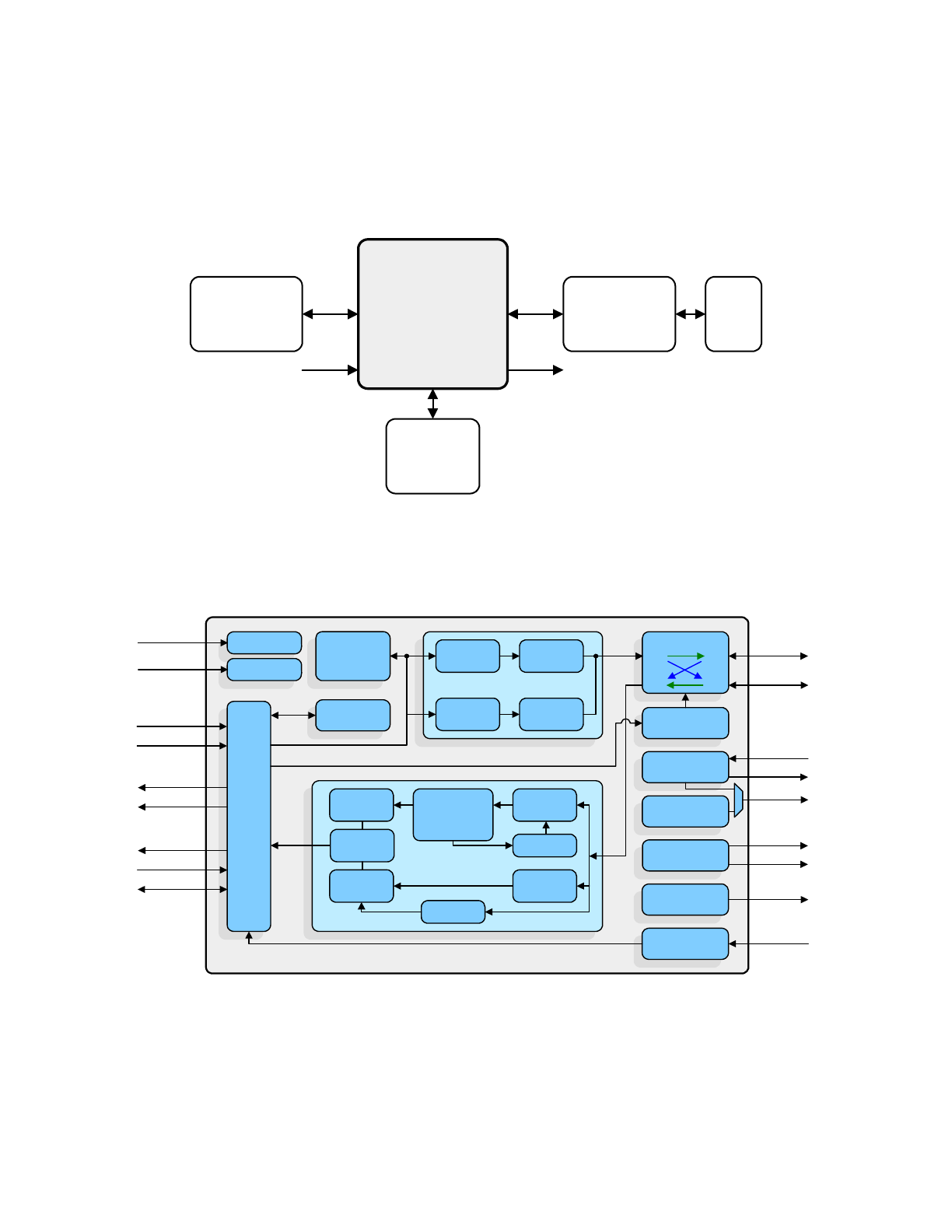
temperature range versions. A typical system application is shown in
Figure 1.1
.
Figure 1.2
provides
an internal block diagram of the device.
Figure 1.1 System Block Diagram
Figure 1.2 Architectural Overview
LAN8742A/
LAN8742Ai
10/100
Ethernet
MAC
RMII
Mode
LED
Transformer
Crystal or
Clock
Oscillator
MDI
RJ45
RM
II Lo
gi
c
Interrupt
Generator
LEDs
PLL
Receiver
DSP System:
Clock
Data Recovery
Equalizer
Squeltch
& Filters
Analog-to-
Digital
10M RX
Logic
100M RX
Logic
100M PLL
10M PLL
Transmitter
10M
Transmitter
100M
Transmitter
10M TX
Logic
100M TX
Logic
Central Bias
PHY Address
Latches
LAN8742A/LAN8742Ai
RBIAS
LED1
nINT/
REFCLKO
XTAL2
XTAL1/CLKIN
LED2
Management
Control
Mode Control
Reset Control
MDIX
Control
HP Auto-MDIX
RXP/RXN
TXP/TXN
TXD[0:1]
TXEN
RXD[0:1]
RXER
CRS_DV
MDC
MDIO
Auto-
Negotiation
nRST
MODE[0:2]
SMI
PHYAD0
WoL
Small Footprint RMII 10/100 Ethernet Transceiver with HP Auto-MDIX and flexPWR
®
Technology
Datasheet
Revision 1.1 (05-21-13)
10
SMSC LAN8742A/LAN8742Ai
DATASHEET
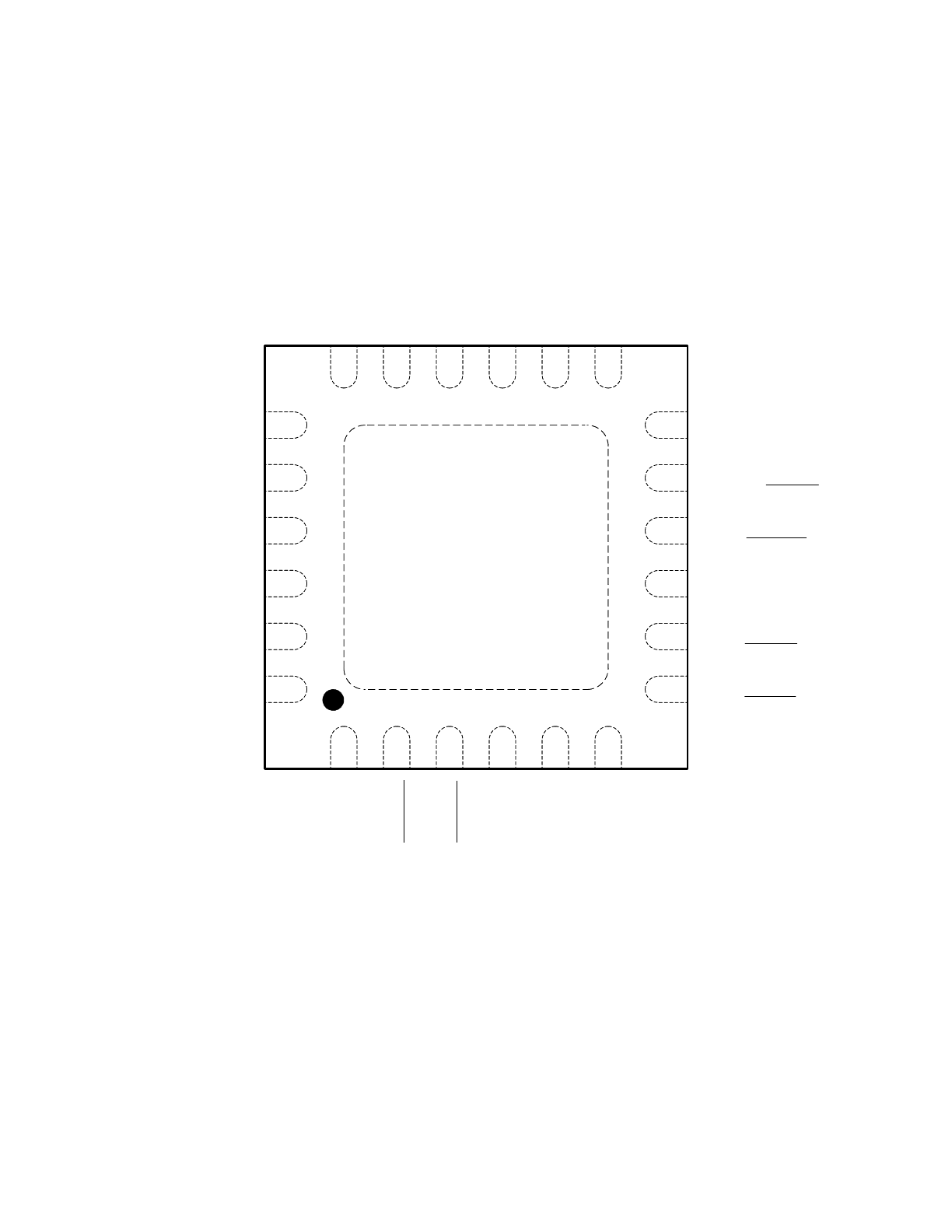
Chapter 2 Pin Description and Configuration
Note: When a lower case “n” is used at the beginning of the signal name, it indicates that the signal
is active low. For example, nRST indicates that the reset signal is active low.
Figure 2.1 24-SQFN Pin Assignments (TOP VIEW)
VSS
NOTE: Exposed pad (VSS) on bottom of package must be connected to ground
SMSC
LAN8742A/LAN8742Ai
24 PIN QFN
(TOP VIEW)
MDIO
1
2
3
4
5
6
7
8
9
10
11
12
18
17
16
15
14
13
24
23
22
21
20
19
VD
DC
R
XTAL1/
CLKI
N
XT
AL2
LED
1/
nIN
T/
nPME/REGOF
F
LE
D2/
nINT/nPME/nINTSEL
VD
D2
A
TXD
1
TX
D0
TX
EN
nR
ST
nI
NT
/RE
FCL
KO
MDC
VDD1A
TXN
TXP
RXN
RXP
RBIAS
CRS_DV/MODE2
RXER/PHYAD0
VDDIO
RXD0/MODE0
RXD1/MODE1