
2009-2012 Microchip Technology Inc.
DS22180C-page 1
RE46C144
Features
• Internal Power-On Reset
• Low Quiescent Current Consumption
• ESD Protection on all Pins
• Interconnect up to 40 Detectors
• 10 Minute Timer for Sensitivity Control
• 75% Duty Cycle Horn Pattern
• Internal Low Battery and Chamber Test
• Compatible with Allegro A5358
• UL Recognized per File S24036
General Description
The RE46C144 is a low-power, CMOS photoelectric-
type smoke detector IC. With minimal external
components, this circuit will provide all the required
features for a photoelectric-type smoke detector.
The design incorporates a gain selectable photo
amplifier for use with an infrared emitter/detector pair.
An internal oscillator strobes power to the smoke
detection circuitry for 100 µs every 10 seconds to keep
standby current to a minimum. If smoke is sensed, the
detection rate is increased to verify an Alarm condition.
A High Gain mode is available for push-button chamber
testing.
A check for a low-battery condition and chamber
integrity is performed every 43 seconds, when in
Standby. The alarm horn pattern utilizes a 75% duty
cycle.
An interconnect pin allows multiple detectors to be
connected such that when one units alarms, all units
will sound.
An internal 10 minute timer can be used for a reduced
sensitivity mode.
The RE46C144 device is recognized by
Underwriters Laboratories for use in smoke
detectors that comply with specification UL217 and
UL268.
Package Types
RE46C144
PDIP, SOIC, SOICN
C1
1
2
3
4
5
6
7
8
16
15
14
13
12
11
10
9
C2
DETECT
STROBE
V
DD
IRED
IO
HORNB
TEST
VSEN
V
SS
ROSC
COSC
LED
FEED
HORNS
CMOS Photoelectric Smoke Detector ASIC with Interconnect
and Timer Mode
RE46C144
DS22180C-page 2
2009-2012 Microchip Technology Inc.
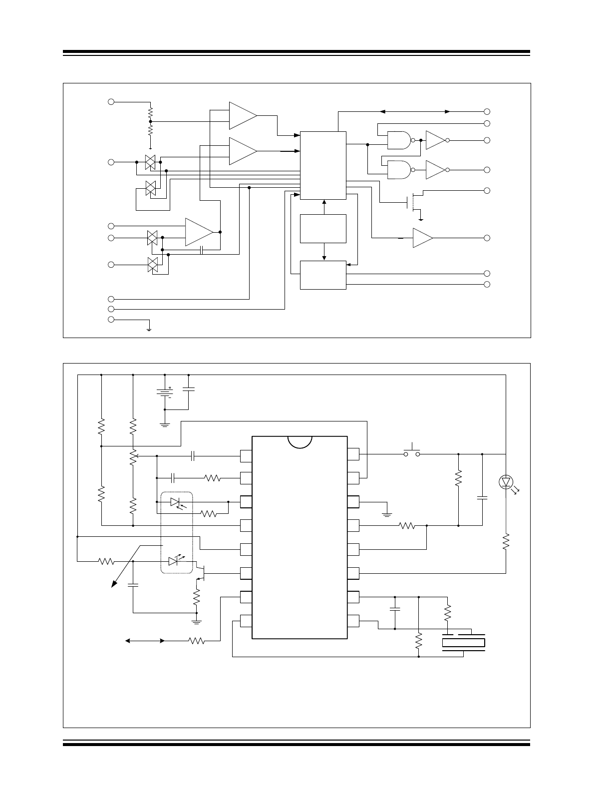
Functional Block Diagram
Typical Application
Logic and
Timing
Bias and
Power Reset
Oscillator
+
-
+
-
VDD (5)
VSEN (15)
C1 (1)
DETECT (3)
C2 (2)
TEST (16)
IO (7)
FEED (10)
HS (9)
LED (11)
IRED (6)
ROSC (13)
COSC (12)
HB (8)
+
-
PHOTOAMP
STROBE (4)
VSS (14)
V
DD
-3.5V
V
DD
-5V
Low Battery
Smoke Comparator
Horn Driver
Push-to-Test
C3
1 µF
C5
1.5nF
R12
10M
R9
100k
R13
330
D3
C6
1.0nF
R10
1.5M
R11
220k
R8
330
R7
22
C4
100 µF
D5
D6
R4
560
C2
4700 pF
C1
.047 µF
R1
4.7k
R2
5k
R3
8.2k
R
ADJ2
R
ADJ1
R6
1k
1
2
3
4
5
14
6
7
8
9
10
11
12
13
15
16
R5
250k
To Other Units
Q3
9v
Battery
Smoke Chamber
Note 1:
C3 should be located as close as possible to the device power pins.
2:
C3 is typical for an alkaline battery. This capacitance should be increased to 4.7 µF or greater for a carbon battery.
3:
R10, R11 and C6 are typical values and may be adjusted to maximize sound pressure.
2009-2012 Microchip Technology Inc.
DS22180C-page 3
RE46C144
1.0
ELECTRICAL
CHARACTERISTICS
1.1
Absolute Maximum Ratings†
V
DD
....................................................................................15V
Input Voltage Range Except FEED, IO .......... V
IN
= -.3V to V
DD
+.3V
FEED Input Voltage Range ..................... V
INFD
=-10 to +22V
IO Input Voltage Range................................. V
IO1
= -.3 to 15V
Input Current except FEED................................... I
IN
= 10 mA
Operating Temperature ................................T
A =
-25 to +75°C
Storage Temperature ............................T
STG
= -55 to +125°C
Maximum Junction Temperature......................... T
J
= +150°C
† Notice:
Stresses above those listed under “Maximum
ratings” may cause permanent damage to the device.
This is a stress rating only and functional operation of
the device at these or any other conditions above those
indicated in the operation listings of this specification is
not implied. Exposure to maximum rating conditions for
extended periods may affect device reliability.
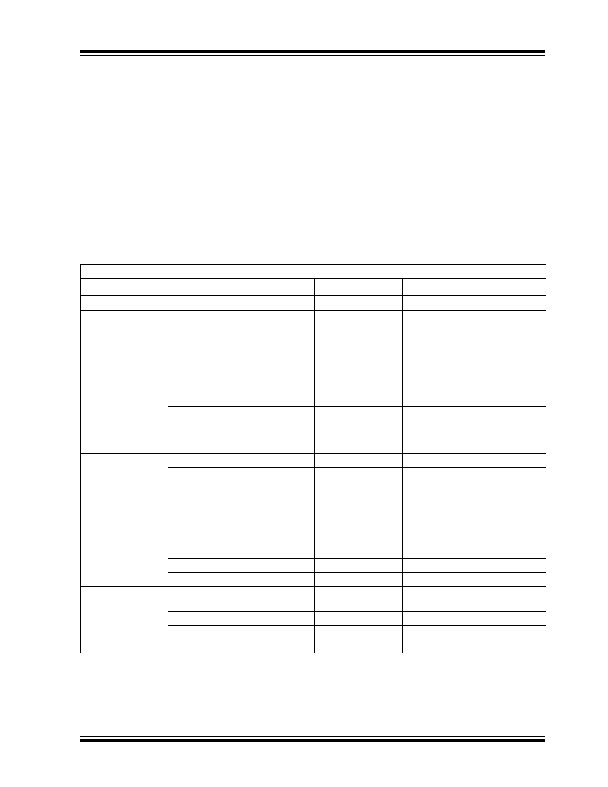
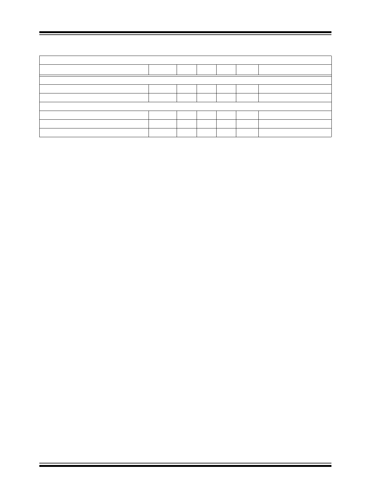
DC ELECTRICAL CHARACTERISTICS
DC Electrical Characteristics:
Unless otherwise indicated, all parameters apply at T
A
= -25°C to +75°C, V
DD
= 9V.
Parameter
Symbol
Test Pin
Min.
Typ.
Max.
Units
Conditions
Supply Voltage
V
DD
5
6
—
12
V
Operating
Supply Current
I
DD1
5
—
4
6
µA
Configured as in
Typical
Application
, COSC=V
SS
I
DD2
5
—
5.5
8
µA
Configured as in
Typical
Application
, V
DD
= 12V,
COSC = V
SS
I
DD3
5
—
—
2
mA
Configured as in
Typical
Application
, STROBE on,
IRED off, V
DD
= 12V
I
DD4
5
—
—
3
mA
Configured as in
Typical
Application
, STROBE on,
IRED on, V
DD
= 12V,
Note 1
Input Voltage High
V
IH1
10
6.2
—
—
V
FEED
V
IH2
7
3.2
—
—
V
No Local Alarm, IO as
input
V
IH3
15
1.6
—
—
V
V
SEN
V
IH4
16
8.5
—
—
V
TEST
Input Voltage Low
V
IL1
10
—
—
2.7
V
FEED
V
IL2
7
—
—
1.5
V
No Local Alarm, IO as
Input
V
IL3
15
—
—
.5
V
VSEN
V
IL4
16
—
—
7
V
TEST
Input Leakage Low
I
IL1
1, 2, 3
—
—
-100
nA
V
DD
= 12V, COSC = 12V,
STROBE active
I
IL2
10, 12
—
—
-100
nA
V
DD
= 12V, V
IN
= V
SS
I
IL3
15, 16
—
—
-1
µA
V
DD
= 12V, V
IN
= V
SS
I
IFD
10
—
—
-50
µA
FEED = -10V
Note 1:
Does not include Q3 emitter current.
2:
Not production tested.
3:
Typical values are for design information and are not ensured.
4:
Limits over the specified temperature range are not production tested and are based on characterization
data.

RE46C144
DS22180C-page 4
2009-2012 Microchip Technology Inc.
Input Leakage High
I
IH1
1, 2
—
—
100
nA
V
DD
= 12V, V
IN
= V
DD
,
STROBE active
I
IH2
3, 10, 12
—
—
100
nA
V
DD
= 12V, V
IN
= V
DD
I
HFD
10
—
—
50
µA
FEED = 22V
Input Pull Down
Current
I
PD1
16
.25
—
10
µA
V
IN
= V
DD
I
PD2
15
.1
.25
.5
µA
V
IN
= V
DD
I
PDIO1
7
20
—
80
µA
V
IN
= V
DD
I
PDIO2
7
—
—
140
µA
V
IN
= 15V, V
DD
= 12V
Output Leakage
Current Low
I
OZL1
11, 13
—
—
-1
µA
Output Off, Output = V
SS
Output Leakage
Current High
I
OZH1
11, 13
—
—
1
µA
Output Off, Output = V
DD
Output Voltage Low
V
OL1
8, 9
—
—
1
V
Iol = 16 mA, V
DD
= 6.5V
V
OL2
13
—
.5
—
V
Iol = 5 mA, V
DD
= 6.5V
V
OL3
11
—
—
.6
V
Iol = 10 mA, V
DD
= 6.5V
Output Voltage High
V
OH1
8, 9
5.5
—
V
Iol = -16 mA, V
DD
= 6.5V
Output Current
I
IOH1
7
-4
—
-16
mA
Alarm,
V
IO
= V
DD
- 2V or V
IO
= 0V
I
IODMP
7
5
—
—
mA
At Conclusion of Local
Alarm or Test, V
IO
= 1V
Low Battery
Alarm Voltage
V
LB
5
6.9
7.2
7.5
V
Output Voltage
V
STOF
4
V
DD
– .1
—
—
V
STROBE off, V
DD
=12V,
I
OUT
= -1 µA
V
STON
4
V
DD
– 5.25 V
DD
– 5 V
DD
- 4.75
V
STROBE on, V
DD
= 9V,
I
OUT
= 100 µA to 500 µA
V
IREDOF
6
—
—
.1
V
IRED off, V
DD
= 12V,
I
OUT
= 1 µA
V
IREDON
6
2.85
3.1
3.35
V
IRED on, V
DD
= 9V
I
OUT
= 0 to -6 mA,
T
A
= +25°C
Common Mode
Voltage
V
CM1
1, 2, 3
.5
—
V
DD
– 2
V
Local smoke,
Push-to-Test or Chamber
Test,
Note 2
Smoke Compare
Reference
V
REF
—
V
DD
– 3.7
—
V
DD
– 3.3
V
Internal Reference
Temperature
Coefficient
T
CST
4
—
.01
—
%/ºC V
DD
= 6V to 12V,
STROBE Output Voltage
T
CIRED
6
—
.3
—
%/ºC V
DD
= 6V to 12V,
IRED Output Voltage
Line Regulation
∆V
STON
4, 5
—
-50
—
dB
Active, V
DD
= 6V to 12V
∆V
IREDON
6, 5
—
-30
—
dB
Active, V
DD
= 6V to 12V
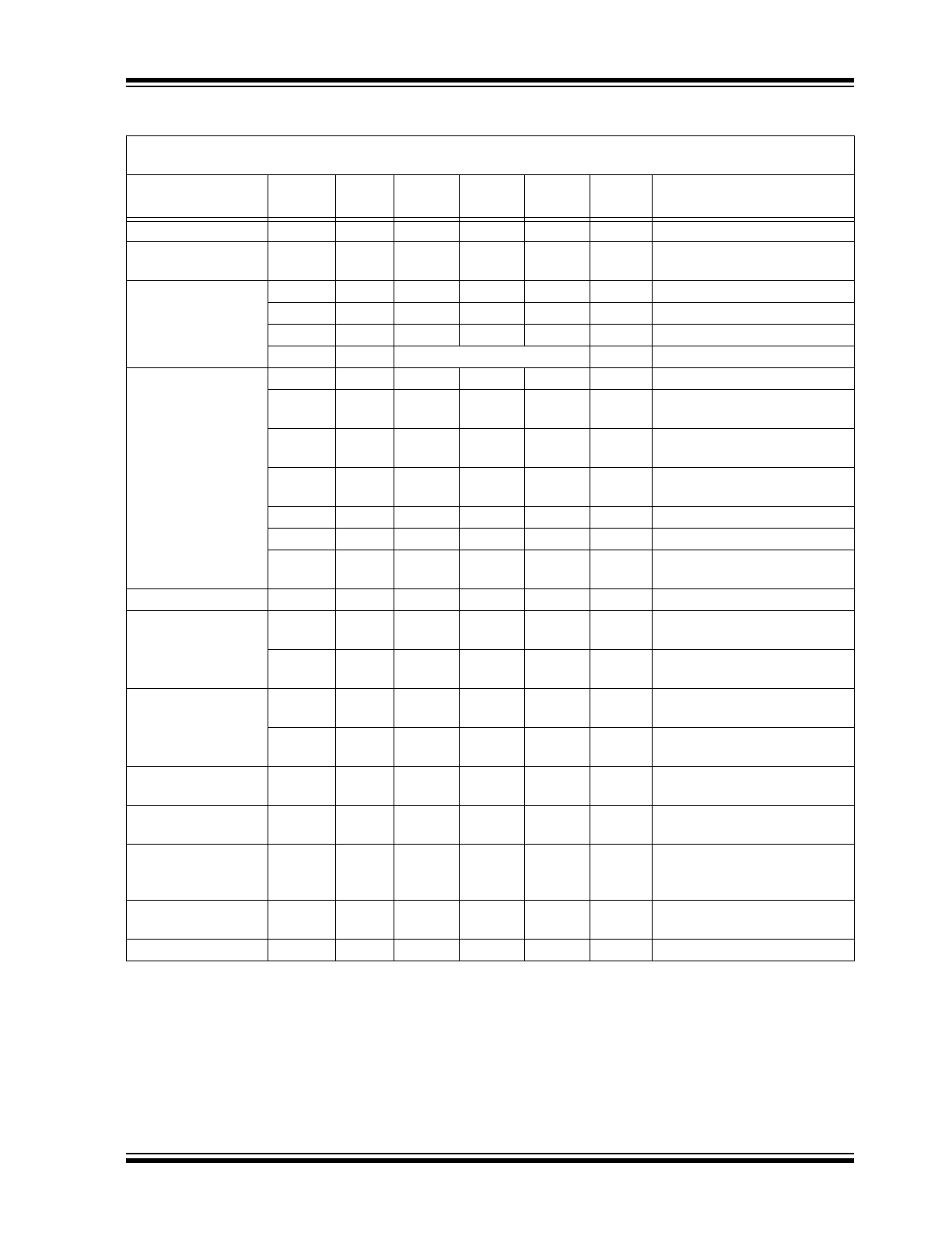
DC ELECTRICAL CHARACTERISTICS (CONTINUED)
DC Electrical Characteristics:
Unless otherwise indicated, all parameters apply at T
A
= -25°C to +75°C, V
DD
= 9V.
Parameter
Symbol
Test Pin
Min.
Typ.
Max.
Units
Conditions
Note 1:
Does not include Q3 emitter current.
2:
Not production tested.
3:
Typical values are for design information and are not ensured.
4:
Limits over the specified temperature range are not production tested and are based on characterization
data.
2009-2012 Microchip Technology Inc.
DS22180C-page 5
RE46C144
TABLE 1-1:
AC ELECTRICAL CHARACTERISTICS
AC Electrical Characteristics:
Unless otherwise indicated, all parameters apply at T
A
= -25°C to +75°C, V
DD
= 9V,
V
SS
= 0V, Component Values from
Typical Application
; R
9
= 100 K
, R
12
= 10 M
, C
5
= 1.5 nF.
Parameter
Symbol
Test
Pin
Min
Typ
Max
Units
Conditions
Oscillator Period
T
POSC
12
9.4
10.5
11.5
ms
No alarm condition
LED and
STROBE On Time
T
ON1
11, 4
9.4
10.5
11.5
ms
Operating
LED Period
T
PLED1
11
39
43
47
s
Standby, no alarm
T
PLED2
11
.6
.67
.74
s
Local alarm condition
T
PLED3
11
9.6
10.75
11.8
s
Timer mode, no local alarm
T
PLED4
11
LED IS NOT ON
s
Remote alarm only
STROBE and IRED
Pulse Period
T
PER1
4, 6
9.6
10.75
11.8
s
Standby, no alarm
T
PER1A
4, 6
2.42
2.7
2.96
s
Standby, after one valid smoke
sample
T
PER1B
4, 6
1.21
1.33
1.47
s
Standby, after two consecutive
valid smoke samples
T
PER2
4, 6
1.21
1.33
1.47
s
In Local Alarm (three consecu-
tive valid smoke samples)
T
PER3
4, 6
9.7
10.5
11.8
s
In Remote Alarm
T
PER4
4, 6
300
336
370
ms
Push-button Test
T
PER5
4, 6
39
47
s
Chamber Test or Low-battery
Test, no alarms
IRED On Time
T
ON2
6
94
104
115
µs
Operating
Horn On Time
T
HON1
8, 9
227
252
277
ms
Operating, alarm condition,
Note 1
T
HON2
8, 9
9.5
10.5
11.5
ms
Low Battery or Failed Chamber
Test, no alarm
Horn Off Time
T
HOF1
8, 9
76
84
92
ms
Operating, Alarm Condition,
Note 1
T
HOF3
8, 9
39
43
47
s
Low Battery or Failed Chamber
Test, no alarm
IO Charge Dump
Duration
T
IODMP
7
.91
1.46
s
At conclusion of local alarm or
test
IO Delay
T
IODLY1
7
0
s
From start of local alarm to IO
Active
IO Filter
T
IOFILT
7
600
ms
IO pulse-width ensured to be
filtered. IO as input, no local
alarm
Remote Alarm Delay
T
IODLY2
7
.75
1.65
s
No local alarm, from IO Active
to Horn Active
Timer Period
T
TPER
7
8.5
10
Min
No alarm condition,
Note 2
Note 1:
See timing diagram for Horn Temporal Pattern
2:
During the Timer mode, the LED period is 10.5 seconds. The LED period will return to 43 seconds at the
conclusion of the Timer mode.
3:
T
POSC
and T
ON2
are 100% production tested. All other timing is guaranteed by functional testing.
4:
Typical values are for design information and are not ensured.
5:
Limits over the specified temperature range are not production tested and are based on characterization
data.
RE46C144
DS22180C-page 6
2009-2012 Microchip Technology Inc.
TEMPERATURE CHARACTERISTICS
Electrical Specifications:
Unless otherwise indicated, V
DD
= 9V, V
SS
= 0V
Parameters
Symbol
Min.
Typ.
Max.
Units
Conditions
Temperature Ranges
Operating Temperature Range
T
A
-25
—
+75
°C
Storage Temperature Range
T
STG
-55
—
+125
°C
Thermal Package Resistances
Thermal Resistance, 16L-PDIP
θJ
A
—
70
—
°C/W
Thermal Resistance, 16L-SOIC (150 mil.)
θJ
A
—
86.1
—
°C/W
Thermal Resistance, 16L-SOIC (300 mil.)
θJ
A
—
80
—
°C/W
2009-2012 Microchip Technology Inc.
DS22180C-page 7
RE46C144
2.0
PIN DESCRIPTION
The descriptions of the pins are listed in .
2.1
High/Normal Gain Capacitor Pins
(C1, C2)
The capacitor connected to the C1 pin sets the photo
amplifier gain (high) for the push-to-test and chamber
sensitivity test. The size of this capacitor will depend on
the chamber background reflections. A = 1+(C1/10),
where C1 is expressed
in pF. The gain should be
<10000.
The capacitor connected to the C2 pin sets the photo
amplifier gain (normal) during Standby. The value of
this capacitor will depend on the smoke sensitivity
required. A = 1+(C2/10), where C2 is expressed
in pF.
2.2
Photo Diode Input (DETECT)
This input is normally connected to the cathode of an
external photo diode operated at zero bias.
2.3
Strobed Detection
Negative Supply (STROBE)
Regulated output voltage of V
DD
-5 which is active
during a test for smoke. This output is the negative side
of the photo amplifier reference circuitry.
2.4
Positive Power Supply (V
DD
)
The V
DD
pin is the device’s positive power supply input.
2.5
Infrared Emitting Diode Pin (IRED)
Provides a regulated pulsed output voltage pre-driver
for the infrared emitter. This output usually drives the
base of an NPN transistor.
2.6
Interconnect Pin (I/O)
This bidirectional pin provides the capability to
interconnect many detectors in a single system. This
pin has an internal pull-down device.
2.7
Horn Brass, Inverted Output (HB)
The HB pin is connected to the metal electrode of a
piezoelectric transducer.
2.8
Horn Silver Output Pin (HS)
The HS pin is a complementary output to HB and
connects to the ceramic electrode of the piezoelectric
transducer.
TABLE 2-1:
PIN FUNCTION TABLE
RE46C144
PDIP, SOIC, SOICN
Symbol
Function
1
C1
High Gain Capacitor Pin
2
C2
Normal Gain Capacitor Pin
3
DETECT
Photo Diode Input
4
STROBE
Strobed Detection Negative Supply
5
V
DD
Positive Power Supply
6
IRED
Infrared Emitting Diode Pin
7
IO
Interconnect Pin
8
HB
Horn Brass, Inverted Output
9
HS
Horn Silver Output
10
FEED
Horn Feedback Pin
11
LED
LED Driver Pin
12
COSC
Oscillator Capacitor Input
13
ROSC
Oscillator Resistor Drive Low
14
V
SS
Negative Power Supply
15
VSEN
HushTimer Sensitivity Pin
16
TEST
Test Pin

RE46C144
DS22180C-page 8
2009-2012 Microchip Technology Inc.
2.9
Horn Feedback Pin (FEED)
Usually this pin is connected to the feedback electrode
through a current limiting resistor. If not used, this pin
must be connected to V
DD
or V
SS
.
2.10
LED Driver Pin (LED)
This pin is an open drain NMOS output used to drive a
visible LED.
2.11
Oscillator Capacitor Input (COSC)
A capacitor connected to this pin, with a parallel
resistor, sets the internal clock low time, which is
approximately the clock period.
2.12
Oscillator Resistor Drive Low
(ROSC)
A resistor between this pin and COSC pin sets the
internal clock high time. This also sets the IRED pulse
width (100 - 200 µs).
2.13
Hush Timer Sensitivity Pin (VSEN)
In Timer mode, this input pin can be used to set an
external smoke comparator reference.
2.14
TEST Pin
This input is used to invoke two test modes and the
timer mode. This input has an internal pull-down.

2009-2012 Microchip Technology Inc.
DS22180C-page 9
RE46C144
3.0
DEVICE DESCRIPTION
3.1
Standby Internal Timing
With the external components specified in the
illustration
Typical Application
for ROSC and COSC,
the internal oscillator has a nominal period of 10 ms.
Normally the analog circuitry is powered down to
minimize standby current (typically 4 µA at 9V). Once
every 11 seconds, the detection circuitry (normal gain)
is powered up for 10 ms. Prior to completion of the
10 ms period, the IRED pulse is active for 100 µs. At
the conclusion of the 10 ms period, the photo amplifier
is compared to an internal reference to determine the
chamber status and latched. If a smoke condition is
present, the period to the next detection decreases and
additional checks are made. Three consecutive smoke
detections will cause the device to go into alarm, and
the horn circuit and interconnect will be active.
Once every 43 seconds, the status of the battery volt-
age is checked. This status is checked and latched at
the conclusion of the LED pulse. In addition, once
every 43 seconds the chamber is activated and, using
the high gain mode (capacitor C1), a check of the
chamber is made by amplifying background reflections.
If either the low battery or the photo chamber test fails,
the horn will chirp for 10 ms every 43 seconds.
The oscillator period is determined by the values of R9,
R12 and C5 (see
Typical Application
). The oscillator
period is as follows:
EQUATION 3-1:
3.2
Smoke Detection Circuitry
A comparator compares the photo amp output to an
internal reference voltage. If the required number of
consecutive smoke conditions is met, the device will go
into local alarm and the horn will be active. In local
alarm, the C2 gain is internally increased by
approximately 10% to provide alarm hysteresis.
3.3
Push-to-Test Operation
If the Test input pin is activated (V
IH
), after one internal
clock cycle, the smoke detection rate increases to once
every 330 ms. In this mode, the high-gain capacitor C1
is selected, and background reflections are used to
simulate a smoke condition. After the required
consecutive detections, the device will go into a local
alarm condition. When the Test input is deactivated
(V
IL
) and after one clock cycle, the normal gain
capacitor C1 is selected. The detection rate continues
at once every 330 ms until three consecutive no smoke
conditions are detected. At this point, the device
returns to standby timing.
3.4
LED Operation
In Standby, the LED is pulsed on for 10 ms every
43 seconds. In a local alarm condition or the push-to-
test alarm, the LED pulse frequency is increased to
once every .5 seconds. In the case of a remote alarm
the LED not active. In the Timer mode of operation, the
LED is pulsed on for 10 ms every 10 seconds.
3.5
Interconnect Operation
The bidirectional I/O pin allows for interconnection of
multiple detectors. In a local alarm condition, this pin is
driven high immediately through a constant current
source. Shorting this output to ground will not cause
excessive current. The I/O is ignored as an input during
a local alarm.
The I/O pin also has an NMOS discharge device that is
active for 1 second after the conclusion of any type of
local alarm. This device helps to quickly discharge any
capacitance associated with the interconnect line.
If a remote active high signal is detected, the device
goes into remote alarm and the horn will be active.
Internal protection circuitry allows for the signaling unit
to have a higher supply voltage than the signaled unit,
without excessive current draw.
The interconnect input has a 670 ms nominal digital
filter. This allows for interconnection to other types of
alarms (carbon monoxide, for example) that may have
a pulsed interconnect signal.
Note:
All timing references are nominal. See
electrical characteristics for limits.
T = T
R
+ T
F
Where:
T
R
= .693 x R12 x C5
T
F
= .693 x R9 x C5

RE46C144
DS22180C-page 10
2009-2012 Microchip Technology Inc.
3.6
Low Battery Detection
In Standby, an internal reference is compared to the
voltage divided V
DD
supply. A low battery status is
latched at the conclusion of the LED pulse. The horn
will chirp for 10 ms every 43 seconds, until the low
battery condition no longer exists. The low battery test
is not performed in a local or remote alarm condition.
The low battery notification does not sound in a local or
remote alarm condition.
3.7
Chamber Fail Detection
In Standby, a chamber test is also performed every
43 seconds, by switching to the high gain capacitor C1
and sensing the photo chamber background
reflections. Two consecutive chamber test failures will
also cause the horn to chirp for 10 ms every
43 seconds. The low battery chirp occurs just before
the LED pulse (see
Figure 3-1
). The chamber test and
chamber test failure chirp occurs approximately
21 seconds after the LED pulse. The chamber tests are
not performed in a local or remote alarm condition.
The chamber fail notification does not sound in a local
or remote alarm condition.
3.8
Timer Mode
If resistors R
ADJ1
and R
ADJ2
are in place and a high-to-
low transition occurs on the Test input, the device
enters a 10 minute timer mode. In this mode, the
smoke comparator reference is switched from the
internal V
DD
- 3.5V reference to the voltage that
appears on VSEN (pin 15). This allows the sensitivity to
be modified for the duration of the 10 minute timer
period. The chamber test is performed in Timer mode.
If VSEN is left unconnected or tied to V
SS
, the Timer
mode of operation is inhibited.
3.9
Diagnostic Mode
In addition to the normal function of the Test input, a
special diagnostic mode is available to calibrate and
test the smoke detector. Taking the Test pin below V
SS
and sourcing ~300 µA out of the pin for one clock cycle
will enable the diagnostic mode. In diagnostic mode,
some of the pin functions are redefined. Refer to
Table 3-1
for redefined pin functions in the diagnostic
mode. In addition, in this mode Strobe is always
enabled, and the IRED is pulsed at the clock rate of
10 ms nominal.
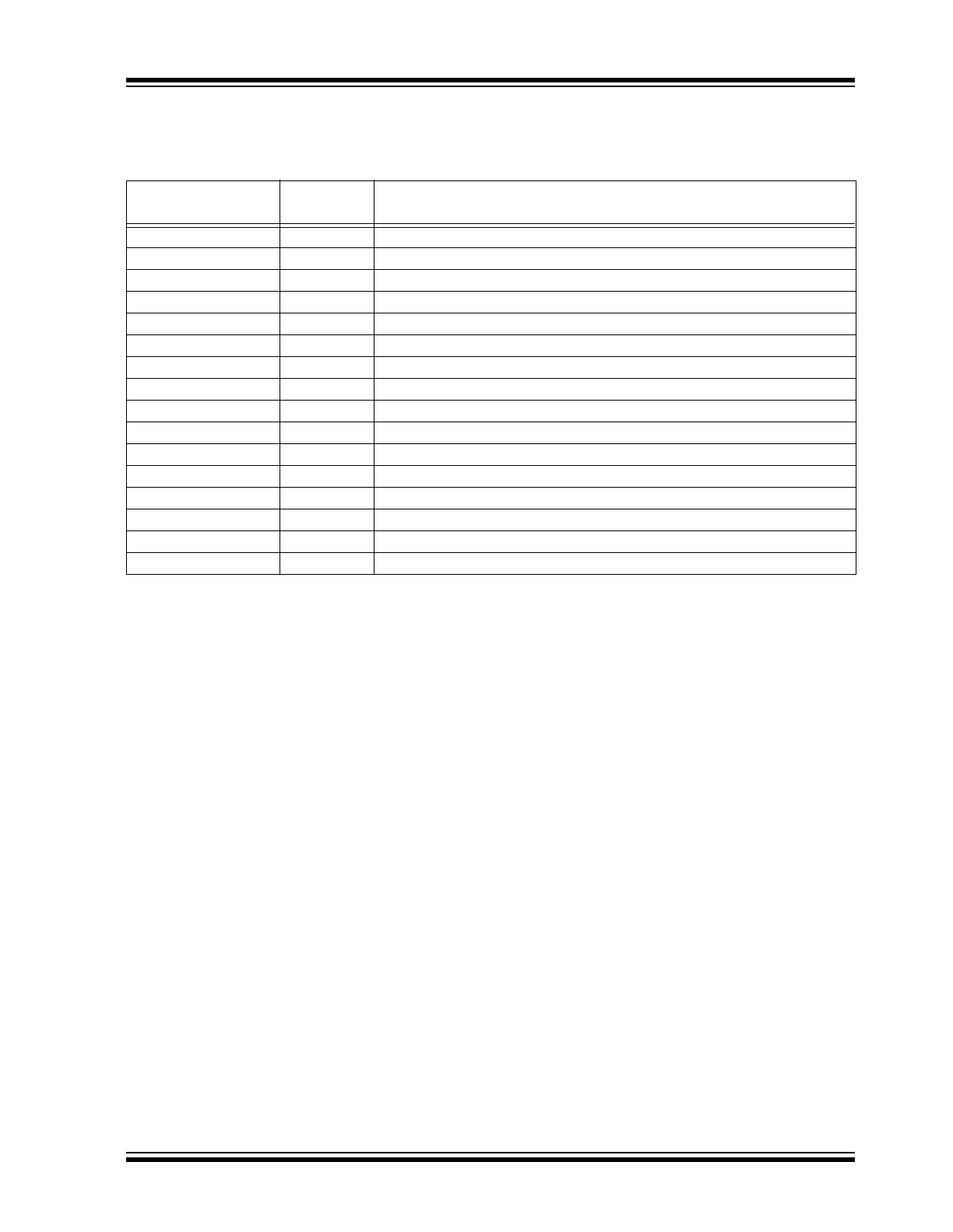
TABLE 3-1:
DIAGNOSTIC MODE PIN FUNCTION
Pin Name
Pin
Number
Function
IO
7
Disabled as an output. A high on this pin directs the photo amplifier output to pin C1 (1)
or C2 (2), determined by the level on VSEN (15). Amplification occurs during the IRED
active time.
VSEN
15
If IO is high, then this pin controls the gain capacitor that is used. If VSEN is low, the
normal gain is selected and the photo amplifier output appears on C1 (1). If VSEN is
high, high gain is selected and the photo amplifier output is on C2 (2).
FEED
10
If VSEN (15) is low, then taking this input high will enable hysteresis, which is a nominal
10% gain increase in normal gain mode.
COSC
12
If desired, this pin can be driven by an external clock.
HORNB
8
This pin becomes the smoke integrator output. A high level indicates that an alarm
condition has been detected.
LED
11
The LED pin is used as a low battery indicator. For V
DD
above the low battery thresh-
old, the open drain NMOS is off. If V
DD
falls below the threshold, the NMOS turns on.