
2004 Microchip Technology Inc.
DS21903A-page 1
PS5100
• PS501 tested, fully populated modules for
evaluation
• Designed to work with 6 to 12 series cell NiMH
and NiCD battery packs
• Performs all major Nickel battery management
functions including:
- Accurate capacity monitoring
- Optional external thermistor configuration for
accurate temperature monitoring
- Supports multiple full charge detection
methods – dT/dt, -dV, programmable
overcharge
• SOC display with four LEDs and a switch
• Fully compliant with industry standard Smart
Battery Data Specification v1.1a
• SMBus v1.1 communication with system host
• High accuracy measurement of charge/discharge
current, voltage and temperature with on-chip
16-bit integrating A/D
• Precise capacity reporting using Microchip
patented algorithms and 3D battery cell models
• 3D models and “learned” parameters stored in
integrated memory
• Extremely low-power operation:
- Run mode: < 170
µ
A typical
- Low-Voltage Sleep mode: < 45
µ
A typical
- Ultra Low-Power mode: < 1
µ
A typical
• Complete hardware and software development
tools available
• Overall mechanical dimensions:
- 0.339 W x 1.772 L (inches)
- 8.6 W x 45.0 L (millimeters)
Part
Number
Description
PS5100
Nickel Chemistry – 6 to 12 series cells
PS501 Nickel Chemistry Battery Manager Module
with LED SOC Display
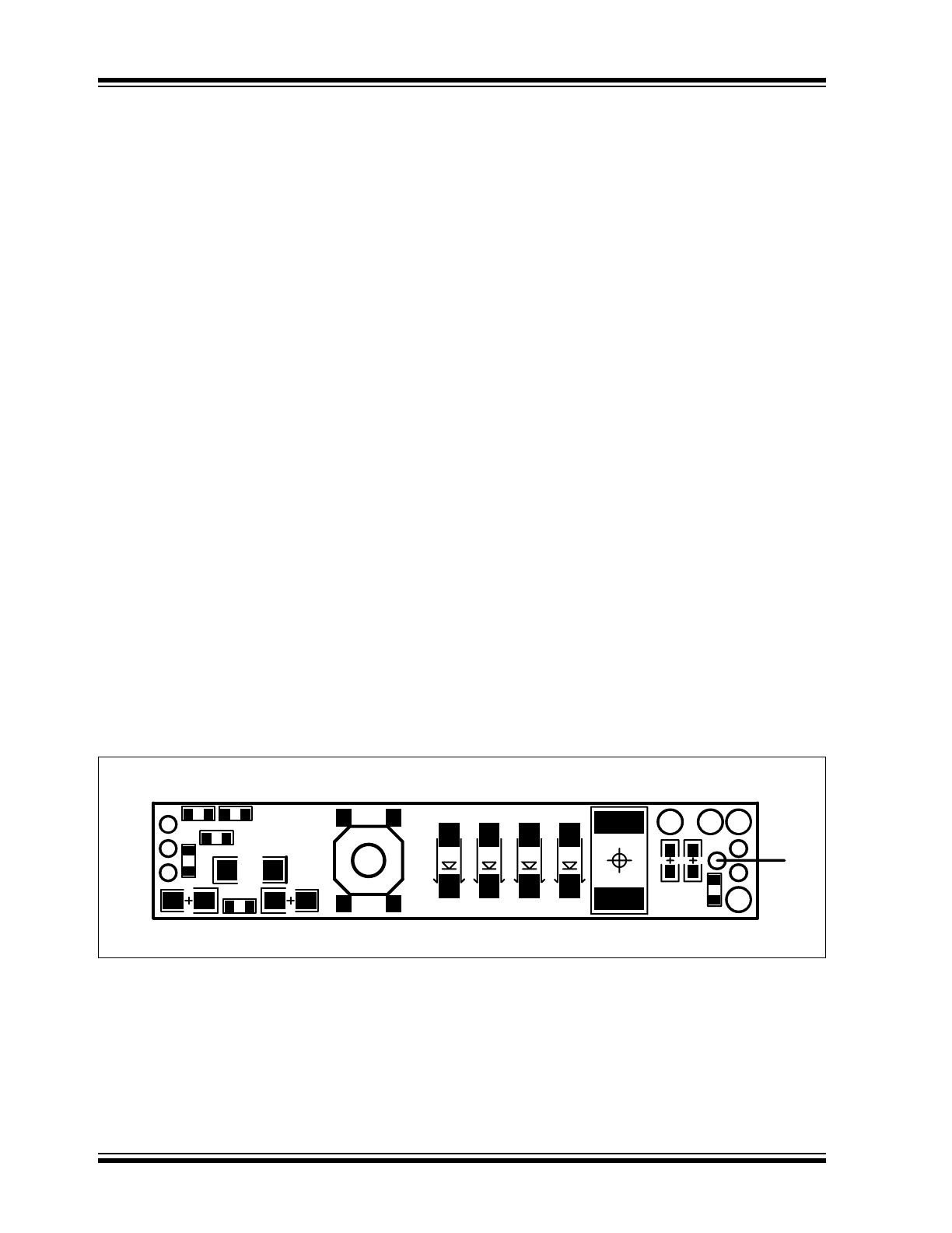
PS5100
DS21903A-page 2
2004 Microchip Technology Inc.
1.0
GENERAL DESCRIPTION
The PS5100 module is a complete Smart Battery
controller subsystem based on the Microchip PS501
battery manager with patented Accuron
®
technology.
The module is designed to operate in a battery pack
consisting of six (6) to twelve (12) series connected
Ni-based cells. The module consists of the Microchip
PS501 battery manager IC with a four LED SOC
display and an optional connection for an external
thermistor.
1.1
Quick Start – Pack Assembly
Follow these directions to assemble a pack with the
PS5100 module.
• Use standard precautions when handling static
sensitive devices.
• Modules should be connected to battery cells in
the order indicated below to insure proper start-up
and operation. Wires should be attached to the
modules first and then connected to the battery
cells as instructed.
• The connection sequence is critical to successful
use of the PS501 family of CMOS ASICs. The
pack positive should be securely connected to the
module first, followed by pack negative.
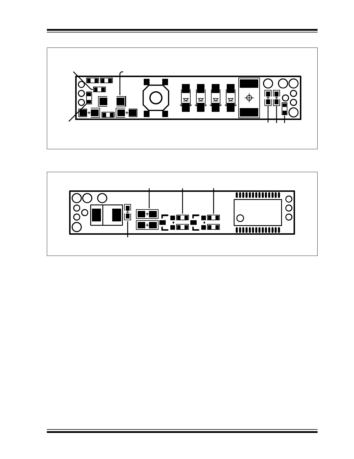
Step 1) Configure the module for optional external
thermistor use. PS5100 modules are
shipped configured to use the internal
temperature sensor only. To add an
external thermistor to the board, remove
resistor R16 and connect the thermistor
across via TN and TR. A parameter change
is required to enable the external thermistor
measurements. Bit 5 of Flags1 must be
cleared.
Step 2) Connect wires to module. Use large
diameter wire (18 AWG-20 AWG) for
current carrying lines from VR and V1. All
others are signal only lines (24 to 22 AWG).
Step 3) Connect V1 to the most positive point on
the battery cell stack.
Step 4) Connect VR to the most negative point on
the battery cell stack.
Step 5) Connect external connector to BN, T, C, D
and BP.
Step 6) Program the assembled pack using
Microchip’s PowerTool™ 500 software and
PowerCal™ 2 board or PowerInfo™ 2
board hardware. The module is shipped
with default configuration values for a six
series cell pack. The Configuration Wizard
guides the user through basic configuration
and initial download. All of the configuration
parameters can be changed at will using
the utilities on the Parameters page in the
PowerTool 500 software.
Step 7) Calibrate the pack using the PowerTool 500
software and PowerCal 2 board hardware.
The pack is now ready for use.
FIGURE 1-1:
CONNECTION POINTS (SIDE 1)
BP
C
T
D
BN
VR V1
VP
TN
TR
2004 Microchip Technology Inc.
DS21903A-page 3
PS5100
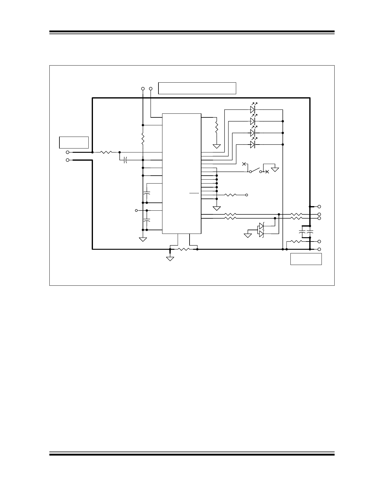
FIGURE 1-2:
BOARD ASSEMBLY (SIDE 1)
FIGURE 1-3:
BOARD ASSEMBLY (SIDE 2)
C17 C18 R35
LED0
LED1
LED2
LED3
SW1
C1
R29 R26
C5 R32 C7
R1
R16
R36
R10
R8
R6
U1
D3
C16
R9
D2 R7 D1 R5

PS5100
DS21903A-page 4
2004 Microchip Technology Inc.
2.0
FUNCTIONAL DESCRIPTION
2.1
PS501-0901 Fuel Gauge
The module fuel gauge provides State-Of-Charge
(SOC) and battery status data in accordance with the
SMBus standards version 1.1. The PS501-0901
monitors the pack voltage, battery temperature and
current to determine SOC and battery status. The
State-Of-Charge calculations compensate for cell self-
discharge and charge acceptance. The remaining time
calculation compensates for temperature and
discharge rate. The parameters for determining battery
status flags and alarm thresholds are all programmable
as is the battery design capacity and the battery perfor-
mance model data. Please refer to the data sheet
“PS501-0901, Single Chip Field Reprogrammable
Battery Manager – Nickel Chemistries” (DS21902) for
details on configuring the PS501-0901.
3.0
BOARD DESCRIPTION
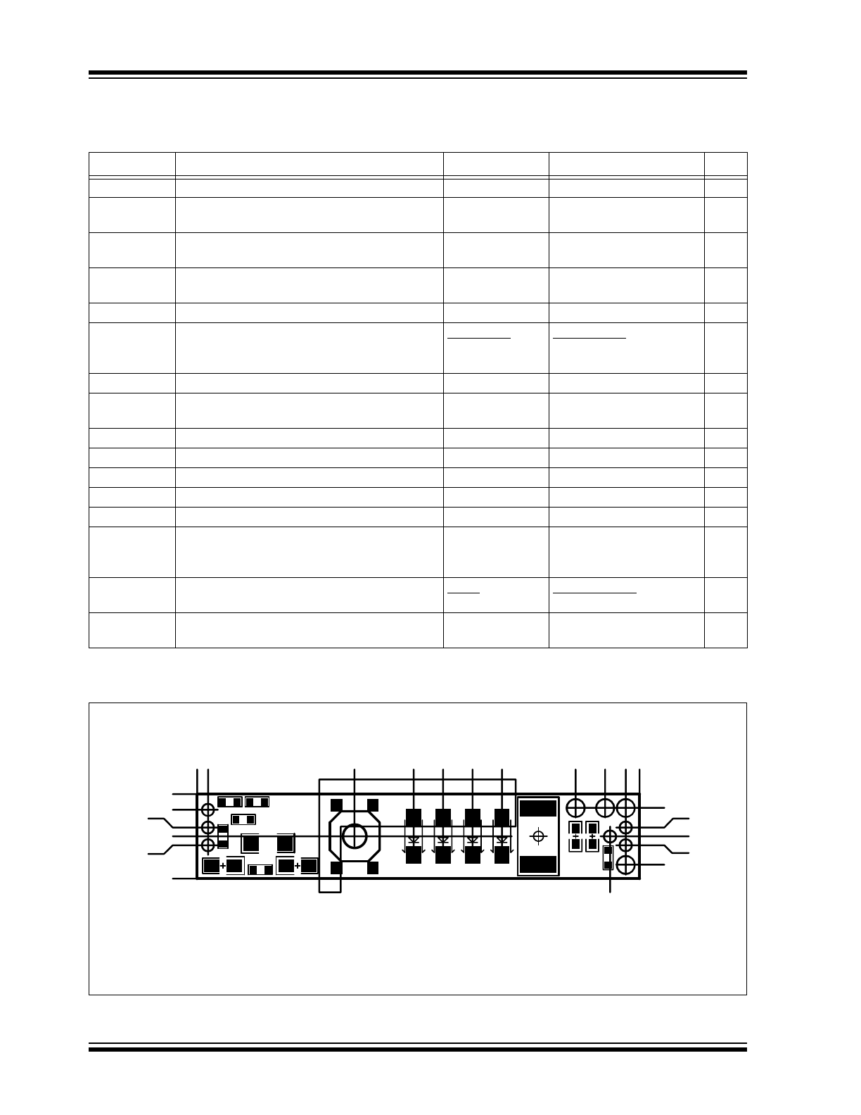
PCB schematics and bill of materials are included here for
completeness. To download full size schematic and BOM,
please visit the Microchip web site (www.microchip.com).
3.1
Mechanical Dimensions
Overall Dimensions: 1772 mils (L) x 339 mils (W).
2004 Microchip Technology Inc.
DS21903A-page 5
PS5100
3.2
Schematic
FIGURE 3-1:
PS5100 BOARD SCHEMATIC
CELL STRING
CONNECTION
TH1 THERMISTOR CONNECTIONS
(SEMITEC 103AT OR 103ETB -- 10K AT 25°C)
V1
VR
R16
221K
TR
TN
C11
330 nF
C15
330 nF
C10
330 nF
R10
0.020
R15
3.65K
GROUND PLANE
CONNECTION
C40
100 nF
PACK
CONNECTIONS
D
C
BP
BN
3
1
2
D40
AZ23C5V6
R42
20
R43
20
R40
240
R41
240
R11
20
V5
V5
R17
20K
V
DDD
1
GPIO(4)
2
GPIO(5)
3
GPIO(6)
4
GPIO(7)
5
SMB-CLK
6
SMB-DTA
7
VC(4)
8
VC(3)
9
VC(2)
10
VC(1)
11
V
DDA
12
V
SSA
13
RSHP
14
RSHN
15
V
NTC
16
V
REFT
17
R
OSC
18
GPIO(8)
19
GPIO(9)
20
GPIOHV1
21
MCLR
22
GPIOHV2
23
GPIO(0)
24
GPIO(1)
25
GPIO(2)
26
GPIO(3)
27
V
SSD
28
U1
PS501
LED0
LED1
LED2
LED3
SW1
T
C41
1.0 nF
R44
103KT16082P
PS5100
DS21903A-page 6
2004 Microchip Technology Inc.
3.3
Bill of Materials
TABLE 3-1:
PS5100 BILL OF MATERIALS
FIGURE 3-2:
PS5100 DIMENSION DETAILS
Symbols
Description
Manufacturer
Manufacturer PN
Qty.
Raw PCB, PS5210
Microchip
04-826192 Rev. 1.1
1
C41
Capacitor, Ceramic, 1.0 nF, 50V, +/-10%, X7R
dielectric, 0603
Panasonic
ECJ-1VB1H102K
1
C40
Capacitor, Ceramic, 100 nF, 25V, +80%/-20%,
Y5V dielectric, 0603
Panasonic
ECJ-1VF1E104Z
1
C10, C11,
C15
Capacitor, Ceramic, 330 nF, 25V, +80%/-20%,
Y5V dielectric, 0805
Panasonic
ECJ-2YF1E334Z
3
LED0-LED3
LED, clear green, 1206 package
Lumex
SML-LX1206GC-TR
4
D40
Dual Zener Diode, 5.6V, +/-5%, 300 mW,
common-anode, SOT-23
Diodes Inc.
General
Semiconductor
AZ23C5V6-7
AZ23-C5V6
1
R15
Resistor, film, 0603, 1%, 3.65 kOhms
Panasonic
ERJ-3EKF3651V
1
R16
Resistor, film, 0603, 1%, 221 kOhms, 25 ppm
TC
Susumu Co. Ltd. RR0816P-2213-D-34D
1
R42-R43
Resistor, film, 0603, 5%, 20 Ohms
Panasonic
ERJ-3GEYJ200V
2
R17
Resistor, film, 0603, 5%, 20 kOhms
Panasonic
ERJ-3GEYJ203V
1
R11
Resistor, film, 0805, 5%, 20 Ohms
Panasonic
ERJ-6GEYJ200V
1
R40-R41
Resistor, film, 0805, 5%, 240 Ohms
Panasonic
ERJ-6GEYJ241V
2
R10
Resistor, metal strip, 2512, 1%, 0.020 Ohms
Vishay
WSL2512-0.020-1%-R86
1
R44
Thermistor, 10 kOhms at 25°C, B value 3435,
-40°C to +125°C operating temperature range,
0603 SMT package
Semitec
103KT1608-2P
1
SW1
Switch, SPST-momentary, push button,
surface mount
ALPS
Fuk Hing Ind.
SKQGADE010
11871501
1
U1
IC, single chip Battery Manager, programmable,
-20°C to +85°C, SSOP-28
Microchip
PS501-I/ST
1
1.4 mm
3.4 mm
4.3 mm
5.2 mm
7.2 mm
0 1.1 mm
16.0 mm
22.0 mm
25.0 mm
28.0 mm
31.0 mm
32.4 mm
38.5 mm
41.5 mm
43.6 mm 45.0 mm
0
1.6 mm
3.4 mm
4.3 mm
5.2 mm
8.6 mm
12.4 mm
14.6 mm
42.0 mm
L-SHAPED BOX INDICATES
AREA CLEAR OF COMPONENTS
ON THE BOTTOM SIDE,
BEHIND THE LEDs AND SWITCH.
EDGE OF BOX UNDER LEDs IS
LOCATED 3.3 mm FROM UPPER EDGE OF PCB.

2004 Microchip Technology Inc.
DS21903A-page 7
PS5100
4.0
DEVELOPMENT TOOL
SUMMARY
Microchip provides all the necessary hardware and
software to enable easy tailoring of battery control algo-
rithm parameters and cell performance models to meet
specific application requirements and attain the highest
accuracy available anywhere. Table 4-1 summarizes
the development tool offering from Microchip to support
the PS5100. Please refer to the Microchip web site for
ordering information and design documentation
(including schematics) at www.microchip.com.
4.1
Reference Documents
This data sheet provides an overview of the PS5100
Battery Manager module. For further information on the
PS501-0901 and development tool operations, please
refer to the following documents available for download
at www.microchip.com.
TABLE 4-1:
MICROCHIP DEVELOPMENT TOOL SUMMARY
TABLE 4-2:
MICROCHIP REFERENCE DOCUMENTS
Development Tool
Use
PowerInfo™ 2 hardware with PowerTool™ 500
software (PS051)
Read and write Smart Battery data values, memory programming
PowerCal™ 2 hardware with PowerTool™ 500
software (PS052)
Read and write Smart Battery data values, memory programming,
pack calibration, pack test
Document
Number
Documents Available
DS21902
PS501-0901 Single Chip Field Reprogrammable Battery Manager – Nickel Chemistries
Data Sheet (IC Products)
DS21815
PS051 PowerInfo™ 2 Configuration Interface Data Sheet
DS21817
PS052 PowerCal™ 2 Calibration Platform Data Sheet

PS5100
DS21903A-page 8
2004 Microchip Technology Inc.
NOTES:

2004 Microchip Technology Inc.
DS21903A-page 9
PS5100
Information contained in this publication regarding device
applications and the like is intended through suggestion only
and may be superseded by updates. It is your responsibility to
ensure that your application meets with your specifications.
No representation or warranty is given and no liability is
assumed by Microchip Technology Incorporated with respect
to the accuracy or use of such information, or infringement of
patents or other intellectual property rights arising from such
use or otherwise. Use of Microchip’s products as critical com-
ponents in life support systems is not authorized except with
express written approval by Microchip. No licenses are con-
veyed, implicitly or otherwise, under any intellectual property
rights.
Trademarks
The Microchip name and logo, the Microchip logo, Accuron,
PIC, PICmicro, PowerSmart and SmartShunt are registered
trademarks of Microchip Technology Incorporated in the
U.S.A. and other countries.
SmartSensor is a registered trademark of Microchip
Technology Incorporated in the U.S.A.
PowerCal, PowerInfo, PowerMate, PowerTool and SmartTel
are trademarks of Microchip Technology Incorporated in the
U.S.A. and other countries.
All other trademarks mentioned herein are property of their
respective companies.
© 2004, Microchip Technology Incorporated. Printed in the
U.S.A., All Rights Reserved.
Printed on recycled paper.

DS21903A-page 10
2004 Microchip Technology Inc.
AMERICAS
Corporate Office
2355 West Chandler Blvd.
Chandler, AZ 85224-6199
Tel: 480-792-7200
Fax: 480-792-7277
Technical Support:
480-792-7627
Web Address:
www.microchip.com
Atlanta
Alpharetta, GA
Tel: 770-640-0034
Fax: 770-640-0307
Boston
Westford, MA
Tel: 978-692-3848
Fax: 978-692-3821
Chicago
Itasca, IL
Tel: 630-285-0071
Fax: 630-285-0075
Dallas
Addison, TX
Tel: 972-818-7423
Fax: 972-818-2924
Detroit
Farmington Hills, MI
Tel: 248-538-2250
Fax: 248-538-2260
Kokomo
Kokomo, IN
Tel: 765-864-8360
Fax: 765-864-8387
Los Angeles
Mission Viejo, CA
Tel: 949-462-9523
Fax: 949-462-9608
San Jose
Mountain View, CA
Tel: 650-215-1444
Fax: 650-961-0286
Toronto
Mississauga, Ontario,
Canada
Tel: 905-673-0699
Fax: 905-673-6509
ASIA/PACIFIC
Australia - Sydney
Tel: 61-2-9868-6733
Fax: 61-2-9868-6755
China - Beijing
Tel: 86-10-8528-2100
Fax: 86-10-8528-2104
China - Chengdu
Tel: 86-28-8676-6200
Fax: 86-28-8676-6599
China - Fuzhou
Tel: 86-591-750-3506
Fax: 86-591-750-3521
China - Hong Kong SAR
Tel: 852-2401-1200
Fax: 852-2401-3431
China - Shanghai
Tel: 86-21-6275-5700
Fax: 86-21-6275-5060
China - Shenzhen
Tel: 86-755-8290-1380
Fax: 86-755-8295-1393
China - Shunde
Tel: 86-757-2839-5507
Fax: 86-757-2839-5571
China - Qingdao
Tel: 86-532-502-7355
Fax: 86-532-502-7205
ASIA/PACIFIC
India - Bangalore
Tel: 91-80-2229-0061
Fax: 91-80-2229-0062
India - New Delhi
Tel: 91-11-5160-8632
Fax: 91-11-5160-8632
Japan - Kanagawa
Tel: 81-45-471- 6166
Fax: 81-45-471-6122
Korea - Seoul
Tel: 82-2-554-7200
Fax: 82-2-558-5932 or
82-2-558-5934
Singapore
Tel: 65-6334-8870
Fax: 65-6334-8850
Taiwan - Kaohsiung
Tel: 886-7-536-4816
Fax: 886-7-536-4817
Taiwan - Taipei
Tel: 886-2-2500-6610
Fax: 886-2-2508-0102
Taiwan - Hsinchu
Tel: 886-3-572-9526
Fax: 886-3-572-6459
EUROPE
Austria - Weis
Tel: 43-7242-2244-399
Fax: 43-7242-2244-393
Denmark - Ballerup
Tel: 45-4420-9895
Fax: 45-4420-9910
France - Massy
Tel: 33-1-69-53-63-20
Fax: 33-1-69-30-90-79
Germany - Ismaning
Tel: 49-89-627-144-0
Fax: 49-89-627-144-44
Italy - Milan
Tel: 39-0331-742611
Fax: 39-0331-466781
Netherlands - Drunen
Tel: 31-416-690399
Fax: 31-416-690340
England - Berkshire
Tel: 44-118-921-5869
Fax: 44-118-921-5820
W
ORLDWIDE
S
ALES
AND
S
ERVICE
08/24/04
