
2004 Microchip Technology Inc.
DS21815C-page 1
PS051
Features
• Hardware platform for configuration, verification
and test of Microchip PS70X and PS5XX ICs
• Operates under control of Windows
®
based
PowerMate™ (PS70X) software and
PowerTool™ 500 (PS5XX) software through an
RS-232 port or USB interface to the PC
• Directly connects to assembled PS70X or PS5XX
battery pack
• SMBus communication managed by onboard
processor
• Supports loading and verification of battery
configuration parameters and 3D cell models in
memory
• Pluggable battery connector for convenience and
flexibility
• Terminals for attachment to an external load or
charger
• Powered through USB port or by 12V DC external
supply (included) when connected to RS-232 port
• Production proven EMI/ESD protection
• Overall mechanical dimensions:
- 2.5 W x 4.0 L (inches)
- 63.5 W x 101.6 L (millimeters)
Ordering Information
Development/Test Software
Part No.
Description
PS051
PowerInfo™ 2 Interface Board
Part
No.
Description
PS070 PowerMate™ Software for use with PS70X
PS050 PowerTool™ 500 Software for use with PS5XX
PowerInfo™ 2 Configuration Interface
PS051
DS21815C-page 2
2004 Microchip Technology Inc.
1.0
PRODUCT OVERVIEW
The PowerInfo 2 board is a simple, easy to use hard-
ware interface that supports configuration, verification
and test of Microchip PS70X and PS5XX ICs. It operates
under the control of Microchip’s development/test
software interfaced to a Windows PC.
The PowerInfo 2 board facilitates serial or USB com-
munication between the PC and the SMBus battery
interface. If connected to the PC’s serial (RS-232) port,
the PowerInfo 2 board must be powered through an
external 12V DC power supply. If connected through a
USB port, no additional power is required.
2.0
GENERAL SETUP
The Microchip PowerInfo 2 interface facilitates commu-
nication between a battery containing a Microchip
PS5XX or PS70X IC and a PC running Microchip’s
development/test software. The information that
follows will guide you through the setup of the various
features available.
2.1
Connections
• P1 – Serial (RS-232)
• J1 – USB
• J2 – 12V DC power supply (used with serial
connection only)
• TB1 – Pluggable terminal block for device under
test. Looking into the connector on the board, the
pins from left to right are:
- V+ (VP): Battery pack positive
- C: SMBus clock
- D: SMBus data
- T: T-pin
- V- (VN): Battery pack negative
• TB2 – External charger or load connection
2.2
Jumpers
• ADR – Jumper for board address identification
2.3
USB Setup
The preferred method to connect PowerInfo 2 to the PC
is through the USB port. Connect the USB cable from
J1 on the PowerInfo 2 board to the USB port on the PC.
The board is now powered through the USB connec-
tion. Attach your battery to the TB1 connector and
launch the Microchip development/test software on the
PC.
2.4
RS-232 Setup
Connect the serial cable from P1 on the PowerInfo 2
board to the RS-232 port on the PC. Connect a 12V DC
power supply to J2 and plug it into the electrical outlet.
The board is now powered. Attach your battery to the
TB1 connector and launch the Microchip development/
test software on the PC.
2.5
Charger/Load Setup (Optional)
A battery charger or a load can be attached at TB2 to
exercise the device under test.
3.0
PS700Driver SETUP
The software driver for PS700 was developed for a
PIC
®
microcontroller and can be installed on the
PowerInfo 2 board when using a PS705X module
board or a PS7070 evaluation board. This software
driver is distributed on a PIC16F876 when a license
agreement has been executed.
3.1
Installing PS700Driver
Disconnect the PS051 from power and PC. Remove
the PIC microcontroller at location U1. Keep this IC in
a safe place as it must be replaced to operate the
PS051 with another PowerSmart
®
product, such as
PS501. Install the PS700Driver at location U1. The
PowerInfo 2 board can now be used with the PS700
development products.
3.2
Removing PS700Driver
To use the PS051 with another PowerSmart product,
such as PS501, the PS700Driver must be removed and
the PIC microcontroller originally located at U1
replaced. Disconnect the PS051 from power and PC.
Remove the PS700Driver at location U1. Install the
original PIC microcontroller and reconnect PC and
power connections.
Address
Jumper Position
2-3
1-4
0
X
X
1
X
O
2
O
X
3
O
O
Legend: O = open, X = connect
2004 Microchip Technology Inc.
DS21815C-page 3
PS051
4.0
MECHANICAL DESCRIPTION
PCB schematics and bill of materials are included here
for completeness. To download the full size schematic
and BOM, please visit the Microchip web site at
www.microchip.com.
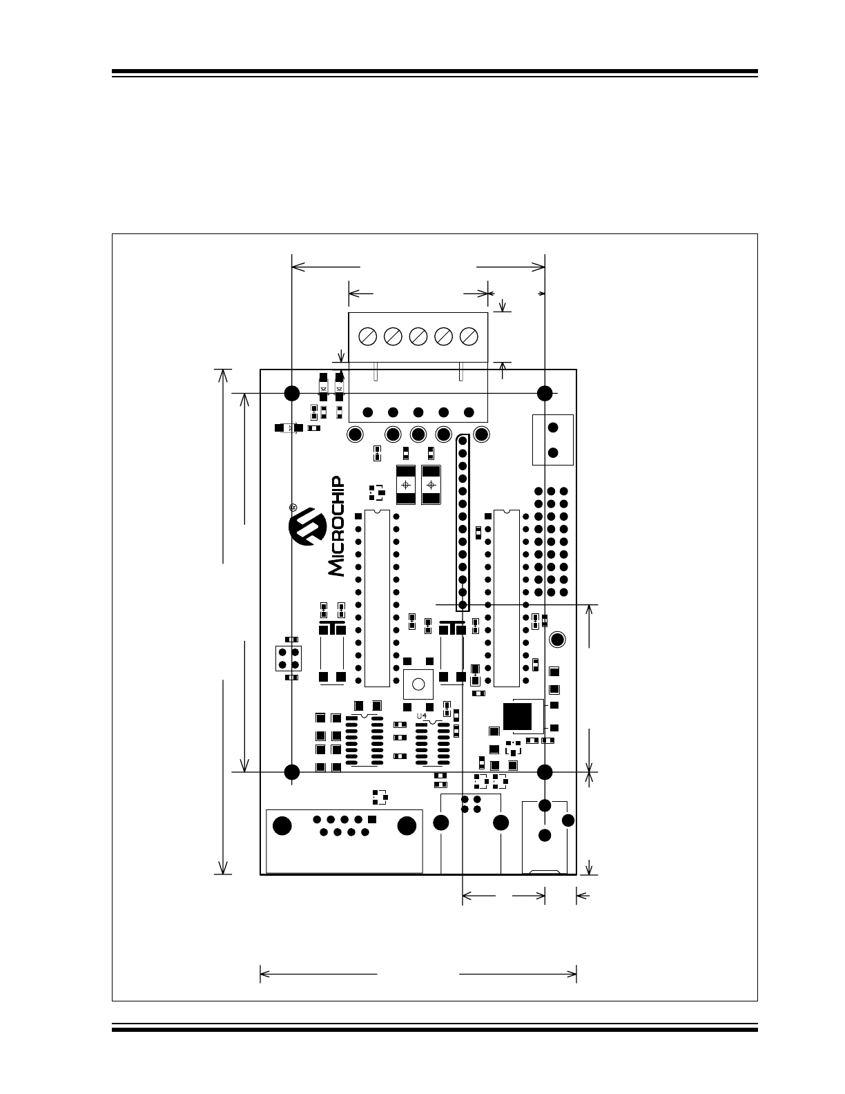
4.1
Mechanical Dimensions
Overall Dimensions: 2.5”W x 4.0”L.
FIGURE 4-1:
PS051 DIMENSION DETAILS
2000 (mil)
4000 (mil)
3000 (mil)
1100 (mil)
1325 (mil)
(1)
813 (mil)
NOTE 1: J3 Pin 1 location from 0, 0 (J3 is not installed in standard configuration).
650 (mil)
(1)
250 (mil)
2500 (mil)
C22
C21
Q3
U3
R10
R9
R2
C25
C24
C23
R3
R4
Y1
C10
C1
1
U1
C4
PWR
C3
R12
R1
1
R13
60 (mil)
400 (mil)
450 (mil)
TB1
TB2
V+
C
D
T
V-
LED2
LED1
R16
R17
R14
R15
D1
R7
U2
1
C19
C13
Y2
C26
C12
C17
R1
R23
C1
1
4
ADR
P1
J1
J2
U5
C2
C20
R5
R6
R22
R8
R18
R19
D2
C18
Q1
Q2
R20
R21
GND
0, 0
RST
PS051
DS21815C-page 4
2004 Microchip Technology Inc.
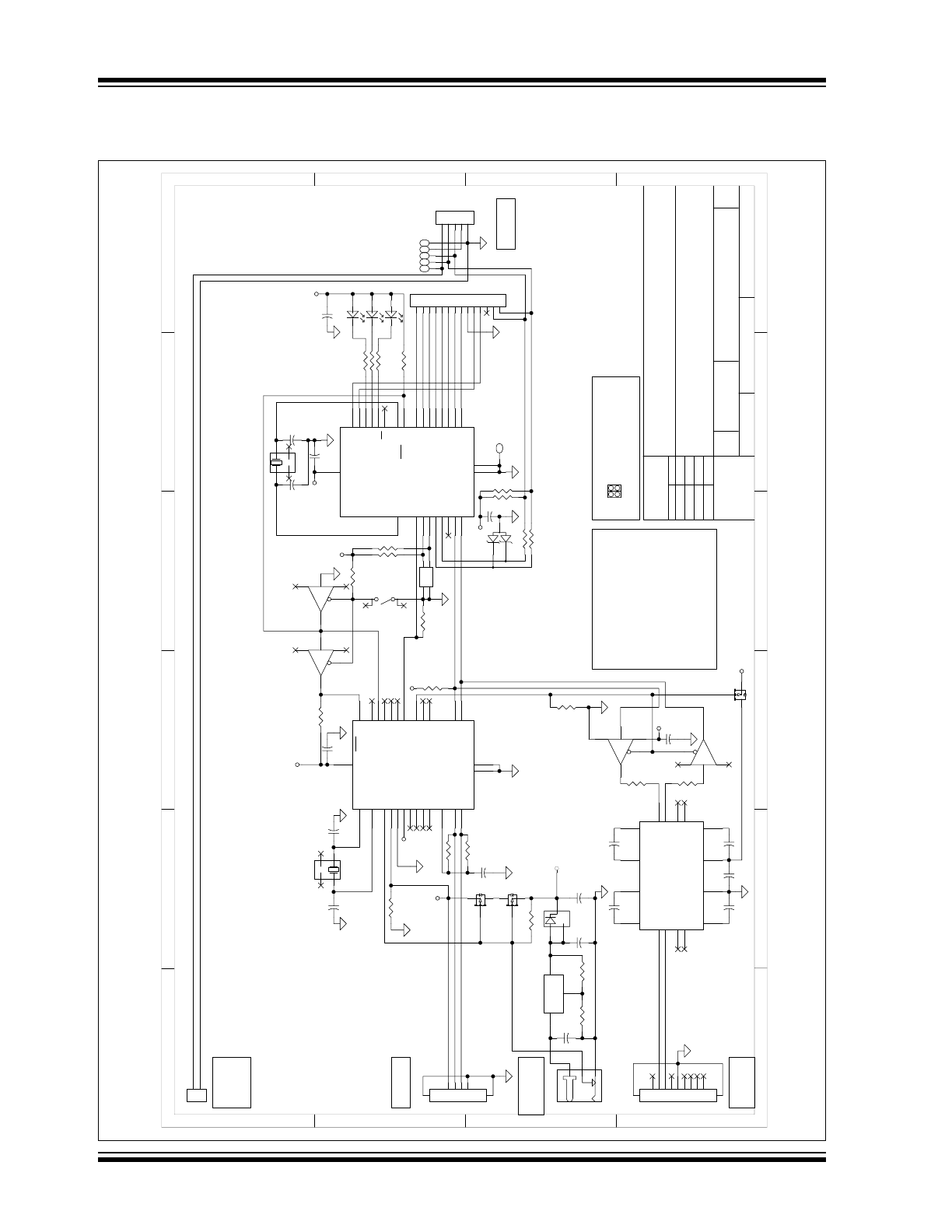
4.2
Schematic
FIGURE 4-2:
PS051 BOARD SCHEMATIC
1
2
3
4
56
A
B
C
D
6
5
4
3
2
1
D
C
B
A
1
Microchip Technology, Inc.
Pow
erSmart Products Group
2745 Dallas Parkw
ay
, Suite 400
Plano, T
X
75093
469-241-0087 Voice/469-241-0106 Fax
1
PowerInfo 2 PCB
03-826159
3.1
14-M
ay
-2003
15:48:30
03-826159 REV 3-1.sch
Sheet
of
*** CO
NFI
DENTI
AL
***
THI
S DOCU
M
ENT CONTA
IN
S
PROPRIE
TARY
IN
FORMAT
ION
THA
T I
S THE I
NTEL
LE
CTU
AL
PROPE
RT
Y OF MICROCHIP
TECHNOL
OGY, I
NC.
SIZE
DRAW
ING NO.
CODE IDENT
NO.
REV
B
FILE
SCALE
NONE
TI
TL
E
APPROVALS
DAT
E
CONT
RACT
NO.
h
tt
p
:/
/www.
m
ic
ro
c
h
ip
.c
o
m
12
DRA
W
N
CHE
CK
E
D
C21
1.0
µ
F
C24
1.0
µ
F
C22
1.0
µ
F
C23
1.0
µ
F
C25
1.0
µ
F
+5V
C19
100 nF
R16
6.8K
R17
6.8K
+5V
COMM-RX
COMM-T
X
SU
S
Sm
-D
Sm
-C
A0
A1
R3
47K
R4
47K
+5V
PW
R
R13
680
RA0/AN0
2
RA1/AN1
3
RA2/AN2/V
REF
-
4
RA3/AN3/V
REF
+
5
RA4/T
0CKI
6
RA5/AN4/SS
7
RB0/INT
21
RB1
22
RB2
23
RB3/PGM
24
RB4
25
RB5
26
RB6/PGC
27
RB7/PGD
28
RC1/T
1OSI/CCP2
12
RC0/T
1OSO/T
1CKI
11
RC2/CCP1
13
RC3/SCK/SCL
14
RC4/SDI/SDA
15
RC5/SDO
16
RC6/T
X/CK
17
RC7/RX/DT
18
V
SS
8
V
SS
19
M
C
LR/V
PP
1
OSC1/CLKIN
9
OSC2/CLKOUT
10
V
DD
20
U1
PIC16F876
1
2
3
4
5
6
7
8
9
G
G
P1
VCC
16
GND
15
D IN1
11
D IN2
10
D OUT
1
14
D OUT
2
7
R OUT
2
9
R IN1
13
R IN2
8
C 1-
3
C 2-
5
C 2+
4
C 1+
1
V+
2
V-
6
R OUT
1
12
U3
DS14C232
1
3
2
J2
R10
10K
3
1
2
D1
AZ23C5V6
1
2
TB
2
1
2
3
4
5
TB
1
+
C
D
T
-
BAT
T
E
RY
PACK
CONNECT
OR
+
-
EXT
ERNAL
CHARGER/
LOAD
CONNECT
ION
1-4
2-3
0
1
2
3
XX
X
X
O
O
OO
ADDRESS
X - CONNECT
O - OPEN
ADR
1
2
34
BOARD ADDRESS
LED1
LED2
R12
680
R11
680
+
-
( J3 IS OPTIONAL)
RST
TX
D
RXD
GND
EXT
. POW
ER
CONNECT
ION
(9-18Vdc, 70mA)
1
2
3
4
5
6
7
8
9
10
11
12
13
14
J3
R15
330
R14
330
5-Mar-2003
R
. C
ASEBO
L
T
+5V
1
2
3
4
ADR
RA0/AN0
2
RA1/AN1
3
RA2/AN2
4
RA3/AN3/V
REF
5
RA4/T
0CKI
6
RA5/AN4
7
RB0/INT
21
RB1
22
RB2
23
RB3
24
RB4
25
RB5
26
RB6
27
RB7
28
RC1/T
1OSI/CCP2
12
RC0/T
1OSO/T
1CKI
11
RC2/CCP1
13
V
USB
14
D-
15
D+
16
RC6/T
X/CK
17
RC7/RX/DT
18
V
SS
8
V
SS
19
MCLR/V
PP
1
OSC1/CLKIN
9
OSC2/CLKOUT
10
V
DD
20
U2
PIC16C745
+5V
C17
100 nF
R9
10K
C20
1.0
µ
F
10
9
8
14
7
U4C
13
12
11
14
7
U4D
T
C
74VHC125FN
1
2
3
14
7
U4A
4
5
6
14
7
U4B
C18
100 nF
+5V
C26
220NF
R8
1.5K
1
1
2
2
3
3
4
4
G1
5
G2
6
J1
+5V
USB
Q1
NDS356AP
Q2
NDS356AP
Q3
NDS356AP
R5
47K
+5V
4
1
3
2
Y2
6.000 MHz
C12
22 pF
C13
22 pF
R1
47K
R7
47K
4
1
3
2
Y1
20.0000 MHz
C10
22 pF
C11
22 pF
R6
47K
+5V
R2
47K
USB
CONNECT
ION
RS-232
CONNECT
ION
(DB-9)
USB COM
M
UNICAT
ION IS AUT
OM
AT
ICALLY
SELECT
ED W
H
ENEVER A USB CABLE IS
PLUGGED INT
O J1.
T
H
E Pow
erInfo 2 DRAW
S POW
ER
FROM
T
H
E USB PORT
, IF AN EXT
ERNAL
SUPPLY
IS NOT
PLUGGED INT
O J2.
NOT
E T
H
AT
T
H
E INSERT
ION OF T
H
E PLUG
INT
O J2 CUT
S OFF USB POW
ER T
O
T
H
E PCB,
W
H
ET
HER T
H
E EXT
ERNAL SUPPLY
IS ON
OR OFF -- SO DO NOT
INSERT
T
H
E PLUG
IF USB-POW
ERED OPERAT
ION IS INT
ENDED.
RS-232 COM
M
UNICAT
ION REQUIRES USE
OF T
H
E EXT
ERNAL 5VDC SUPPLY
,
PLUGGED INT
O J2.
+5V
V
IN
3
V
OUT
2
ADJ
1
U5
LM
317M
DT
3
1
2
D2
ZHCS500
C1
100 nF
C2
1.0
µ
F
R19
365
R18
1.18K
C3
100 nF
C4
100 nF
V+
C
D
T
V-
GND
R20
0
R21
0
R23
OPEN
R22
150K
+5V
TM
TM
FO
R
R
EV
IS
IO
N
H
IS
TO
R
Y,
R
EF
ER
T
O
826159 C
H
A
N
G
E L
O
G

2004 Microchip Technology Inc.
DS21815C-page 5
PS051
4.3
Bill of Materials
TABLE 4-1:
PS051 BILL OF MATERIALS
Symbols
Description
Manufacturer
Manufacturer PN
Qty.
Raw PCB, PowerInfo™ 2
Microchip
04-826159 Rev. 3.1
1
U1
Firmware Specification, PowerInfo™ 2 Main MCU
None
Document
Doc.
U2
Firmware Specification, PowerInfo™/PowerCal™ USB MCU
None
Document
Doc.
C10-C13
Capacitor, Ceramic, 22 pF, 50V, +/-5%, C0G dielectric, 0603
Panasonic
ECJ-1VC1H220J
4
C3-C4,
C17-C19
Capacitor, Ceramic, 100 nF, 25V, +80%/-20%, Y5V dielectric, 0603
Panasonic
ECJ-1VF1E104Z
5
C26
Capacitor, Ceramic, 220 nF, 25V, +/-10%, X7R dielectric, 0805
Panasonic
ECJ-2YB1E224K
1
C2, C20-C25 Capacitor, Ceramic, 1.0
µ
F, 25V, +/-10%, X7R dielectric, 1206
Panasonic
ECJ-3YB1E105K
7
C1
Capacitor, Ceramic, 100 nF, 50V, +/-10%, X7R dielectric, 1206
BC Components 1206B104K500BT
1
LED1-LED2,
PWR
LED, clear green, 1206 package
Lumex
SML-LX1206GC-TR
3
D2
Schottky Diode, 40V, 500 mA, SOT-23
Zetex
ZHCS500TA
1
D1
Dual Zener Diode, 5.6V +/- 5%, 300 mW, common-anode, SOT-23
Diodes Inc.
General Semi.
AZ23C5V6-7
AZ23-C5V6
1
ADR
Connector, shorting jumper, female, 2-position, 100 mil spacing, mates
with 25 mil square pins, 15-microinch gold over nickel
AMP
382811-6
2
TB1
Header, pluggable terminal block, 5.08 mm pitch x 5 positions,
12A/250V, right angle, closed end
Phoenix
1757271
1
U1, U2
IC socket, 28-pin DIP, 300 mil width
Mill-max
110-99-328-41-001
2
J2
Connector, coaxial power, female, 2.0 mm center pin x 6.5 mm
sleeve, right angle PCB mount
Cui Stack
PJ-102A
1
TB2
Terminal block, PCB, 5.08 mm pitch x 2 positions, 16A/250V
Phoenix
1729128
1
V-, GND
Test point, 0.125" OD, for 0.062" hole, black
Keystone
5011
2
V+
Test point, 0.125" OD, for 0.062" hole, red
Keystone
5010
1
C, D, T
Test point, 0.125" OD, for 0.062" hole, white
Keystone
5012
3
J1
Connector, USB type B, right angle PCB mount, shielded
Mill-max
Molex
897-30-004-90-000000
67068-0000
1
Bumper, hemispherical, 0.44"D x 0.20"H, transparent plastic
3M
SJ-5303 (CLEAR)
4
ADR
Connector, break-apart PCB header, straight, 2-row x 36-pin, 100 x
100 mil spacing, 235 mil/100 mil/145 mil length, 25 mil square pins,
10-microinch gold
3M
929665-09-36-I
1
TB1
Pluggable terminal block, 5.08 mm pitch x 5 positions, 12A/250V
Phoenix
1757048
1
P1
Connector, DB9 right angle PCB mount, female sockets
Norcomp
182-009-212-531
1
Q1-Q3
MOSFET, P-channel, -30V, -1.1A, 0.2 ohms, SOT-23
Fairchild Semi.
NDS356AP
3
R18
Resistor, film, 0603, 1%, 1.18 kOhms
Panasonic
ERJ-3EKF1181V
1
R19
Resistor, film, 0603, 1%, 365 ohms
Panasonic
ERJ-3EKF3650V
1
R20-R21
Resistor, 0603, zero ohm
Panasonic
ERJ-3GEY0R00V
2
R8
Resistor, film, 0603, 5%, 1.5 kOhms
Panasonic
ERJ-3GEYJ152V
1
R9-R10
Resistor, film, 0603, 5%, 10 kOhms
Panasonic
ERJ-3GEYJ103V
2
R22
Resistor, film, 0603, 5%, 150 kOhms
Panasonic
ERJ-3GEYJ154V
1
R1-R7
Resistor, film, 0603, 5%, 47 kOhms
Panasonic
ERJ-3GEYJ473V
7
R16-R17
Resistor, film, 0603, 5%, 6.8 kOhms
Panasonic
ERJ-3GEYJ682V
2
R11-R13
Resistor, film, 0603, 5%, 680 ohms
Panasonic
ERJ-3GEYJ681V
3
R14-R15
Resistor, film, 2512, 5%, 330 ohms
Panasonic
ERJ-1TYJ331U
2
RST
Switch, SPST momentary tact, surface mount, 6 mm square,
4.3 mm high, 260 G-force
E-Switch
TL3301NF260QG
1
U1
IC, Microcontroller, 20 MHz, with Flash EEPROM, 28-pin/300 mil DIP,
0°C to 70°C
Microchip
PIC16F876-20/SP
1
U2
IC, Microcontroller, 24 MHz, with USB Interface, 28-pin/300 mil DIP,
-40°C to +85°C
Microchip
PIC16C745-I/SP
1
U4
IC, quad buffer with tri-state outputs, VHCMOS, SO-14, -40°C to +85°C Toshiba
TC74VHC125FN
1
U3
IC, RS-232 transceiver, SO-16, 0°C to 70°C
National Semi.
DS14C232CM
1
U5
IC, Linear Voltage Regulator, adjustable 1.2 - 37V output, 500 mA,
TO-252 package, 0°C to 125°C
National Semi.
LM317MDT
1
Y1
Crystal, 20.0000 MHz, 18 pF load capacitance, surface mount.
Citizen
CM309S20.000MABJTR
1
Y2
Crystal, 6.0000 MHz, 18 pF load capacitance, surface mount.
Citizen
CM309S6.000MABJTR
1
PS051
DS21815C-page 6
2004 Microchip Technology Inc.
5.0
DEVELOPMENT TOOL
SUMMARY
Microchip provides all the necessary hardware and
software to enable easy tailoring of battery control
algorithm parameters and cell performance models to
meet specific application requirements and attain the
highest accuracy available anywhere. Table 5-1 sum-
marizes the development tool offering from Microchip
to support the PS5XX and PS70X products. Please
refer to the Microchip web site for ordering information
and design documentation (including schematics) at
www.microchip.com.
5.1
Reference Documents
This data sheet provides an overview of the PS051
Configuration Interface. For further information on
other products and development tool operations,
please refer to the following documents available for
download at www.microchip.com.
TABLE 5-2:
MICROCHIP REFERENCE DOCUMENTS
TABLE 5-1:
MICROCHIP DEVELOPMENT TOOL SUMMARY
Development Tool
Use
PowerInfo™ 2 hardware with
Development/Test software (PS051)
Read and write battery registers and memory, pack test
PowerCal™ 2 hardware with
Development/Test software (PS052)
Read and write battery registers and memory, pack calibration,
pack test
Document Number
Documents Available
DS21774
PS070 PowerMate™ Development Software Data Sheet
DS21885
PS050 PowerTool™ 500 Development Software User’s Guide

2004 Microchip Technology Inc.
DS21815C-page 7
PS051
Information contained in this publication regarding device
applications and the like is intended through suggestion only
and may be superseded by updates. It is your responsibility to
ensure that your application meets with your specifications.
No representation or warranty is given and no liability is
assumed by Microchip Technology Incorporated with respect
to the accuracy or use of such information, or infringement of
patents or other intellectual property rights arising from such
use or otherwise. Use of Microchip’s products as critical com-
ponents in life support systems is not authorized except with
express written approval by Microchip. No licenses are con-
veyed, implicitly or otherwise, under any intellectual property
rights.
Trademarks
The Microchip name and logo, the Microchip logo, Accuron,
PIC, PICmicro, PowerSmart and SmartShunt are registered
trademarks of Microchip Technology Incorporated in the
U.S.A. and other countries.
SmartSensor is a registered trademark of Microchip
Technology Incorporated in the U.S.A.
PowerCal, PowerInfo, PowerMate, PowerTool and SmartTel
are trademarks of Microchip Technology Incorporated in the
U.S.A. and other countries.
All other trademarks mentioned herein are property of their
respective companies.
© 2004, Microchip Technology Incorporated. Printed in the
U.S.A., All Rights Reserved.
Printed on recycled paper.

DS21815C-page 8
2004 Microchip Technology Inc.
AMERICAS
Corporate Office
2355 West Chandler Blvd.
Chandler, AZ 85224-6199
Tel: 480-792-7200
Fax: 480-792-7277
Technical Support:
480-792-7627
Web Address:
www.microchip.com
Atlanta
Alpharetta, GA
Tel: 770-640-0034
Fax: 770-640-0307
Boston
Westford, MA
Tel: 978-692-3848
Fax: 978-692-3821
Chicago
Itasca, IL
Tel: 630-285-0071
Fax: 630-285-0075
Dallas
Addison, TX
Tel: 972-818-7423
Fax: 972-818-2924
Detroit
Farmington Hills, MI
Tel: 248-538-2250
Fax: 248-538-2260
Kokomo
Kokomo, IN
Tel: 765-864-8360
Fax: 765-864-8387
Los Angeles
Mission Viejo, CA
Tel: 949-462-9523
Fax: 949-462-9608
San Jose
Mountain View, CA
Tel: 650-215-1444
Fax: 650-961-0286
Toronto
Mississauga, Ontario,
Canada
Tel: 905-673-0699
Fax: 905-673-6509
ASIA/PACIFIC
Australia - Sydney
Tel: 61-2-9868-6733
Fax: 61-2-9868-6755
China - Beijing
Tel: 86-10-8528-2100
Fax: 86-10-8528-2104
China - Chengdu
Tel: 86-28-8676-6200
Fax: 86-28-8676-6599
China - Fuzhou
Tel: 86-591-750-3506
Fax: 86-591-750-3521
China - Hong Kong SAR
Tel: 852-2401-1200
Fax: 852-2401-3431
China - Shanghai
Tel: 86-21-6275-5700
Fax: 86-21-6275-5060
China - Shenzhen
Tel: 86-755-8290-1380
Fax: 86-755-8295-1393
China - Shunde
Tel: 86-757-2839-5507
Fax: 86-757-2839-5571
China - Qingdao
Tel: 86-532-502-7355
Fax: 86-532-502-7205
ASIA/PACIFIC
India - Bangalore
Tel: 91-80-2229-0061
Fax: 91-80-2229-0062
India - New Delhi
Tel: 91-11-5160-8632
Fax: 91-11-5160-8632
Japan - Kanagawa
Tel: 81-45-471- 6166
Fax: 81-45-471-6122
Korea - Seoul
Tel: 82-2-554-7200
Fax: 82-2-558-5932 or
82-2-558-5934
Singapore
Tel: 65-6334-8870
Fax: 65-6334-8850
Taiwan - Kaohsiung
Tel: 886-7-536-4816
Fax: 886-7-536-4817
Taiwan - Taipei
Tel: 886-2-2500-6610
Fax: 886-2-2508-0102
Taiwan - Hsinchu
Tel: 886-3-572-9526
Fax: 886-3-572-6459
EUROPE
Austria - Weis
Tel: 43-7242-2244-399
Fax: 43-7242-2244-393
Denmark - Ballerup
Tel: 45-4420-9895
Fax: 45-4420-9910
France - Massy
Tel: 33-1-69-53-63-20
Fax: 33-1-69-30-90-79
Germany - Ismaning
Tel: 49-89-627-144-0
Fax: 49-89-627-144-44
Italy - Milan
Tel: 39-0331-742611
Fax: 39-0331-466781
Netherlands - Drunen
Tel: 31-416-690399
Fax: 31-416-690340
England - Berkshire
Tel: 44-118-921-5869
Fax: 44-118-921-5820
W
ORLDWIDE
S
ALES
AND
S
ERVICE
08/24/04