

2012 Microchip Technology Inc.
Preliminary Information
DS70686B-page 1
MRF24WG0MA/MB
Features:
• IEEE 802.11-compliant RF transceiver
• Serialized unique MAC address
• Data rate: 1 to 11 Mbps for 802.11b / 6 to 54 Mbps
for 802.11g
• Compatible with IEEE 802.11b/g/n networks
• Small size: 21 mm x 31 mm 36-pin Surface Mount
module
• Integrated PCB antenna (MRF24WG0MA)
• External antenna option (MRF24WG0MB) with
ultra-miniature coaxial (U.FL) connector
• Easy integration into final product – accelerates
product development, provides quicker time to
market
• Radio regulation certification for United States
(FCC), Canada (IC), and Europe (ETSI)
• Designed for use with Microchip microcontroller
families (PIC18, PIC24, dsPIC33, and PIC32) with
downloadable Microchip TCP/IP Stack
Operational:
• Single operating voltage: 2.8V to 3.6V (3.3V typical)
• Temperature range: -40°C to +85°C
• Simple, four-wire SPI interface with interrupt
• Low-current consumption:
- RX mode – 156 mA (typical)
- TX mode – 240 mA (+18 dBm typical)
- PS mode – 4 mA (typical)
- Hibernate mode – 0.1 mA (typical)
RF/Analog Features:
• ISM Band 2.400 to 2.484 GHz operation
• Channels 1-11
• DSSS/OFDM modulation
• Application throughput: 4500 kbps
• -95 dBm Typical sensitivity at 1 Mbps
• +18 dBm Typical 802.11b TX power with control
• +16 dBm Typical 802.11g TX power with control
• Integrated low phase noise VCO, RF frequency
synthesizer, PLL loop filter and PA
• Integrated RSSI ADC and I/Q DACs, RSSI
readings available to host
MAC/Baseband Features:
• Hardware CSMA/CA access control, automatic
ACK, and FCS creation and checking
• Automatic MAC packet retransmit
• Hardware Security Engine for AES and
RC4-based ciphers
• Supports 802.1x, 802.1i security: WEP,
WPA-PSK, and WPA-2-PSK.
• Supports Infrastructure, Adhoc, Wi-Fi
®
Direct
Client
• Implements Wi-Fi Protected Setup (WPS), and
SoftAP for easy product commissioning
Applications:
• Utility and Smart Energy:
- Thermostats
- Smart Meters
- White Goods
- HVAC
• Consumer Electronics:
- Remote Control
- Internet Radio
- Home Security
- Toys
• Industrial Controls:
- Chemical Sensors
- HVAC
- Security Systems
- M2M Communication
• Remote Device Management:
- Location and Asset Tracking
- Automotive
- Code Update
• Retail:
- POS Terminals
- Wireless Price Tags
- Digital Remote
• Medical, Fitness, and Health Care:
- Glucose Meters
- Fitness Equipment
- Patient Asset Tracking
MRF24WG0MA/MB Data Sheet
2.4 GHz IEEE 802.11b/g™
MRF24WG0MA/MB
DS70686B-page 2
Preliminary Information
2012 Microchip Technology Inc.
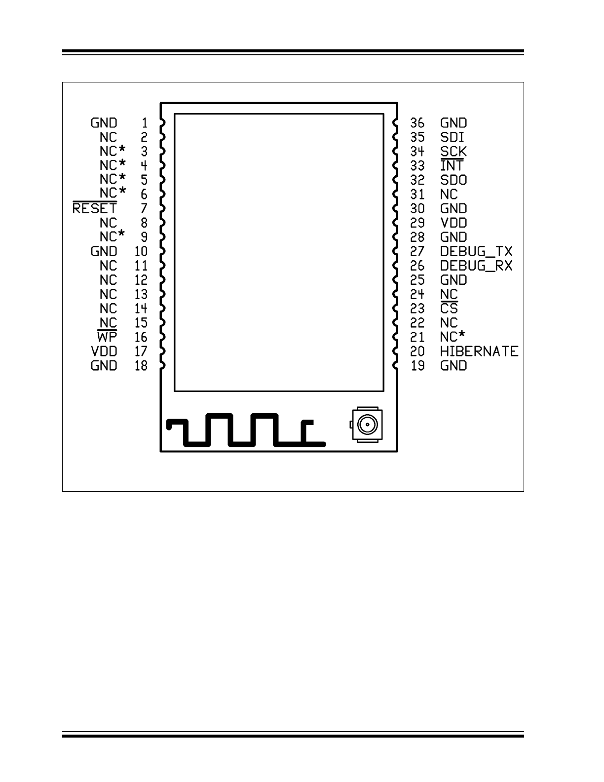
Pin Diagram
Note:
Antenna connector on MRF24WG0MB only.

2012 Microchip Technology Inc.
Preliminary Information
DS70686B-page 3
MRF24WG0MA/MB
Table of Contents
1.0
Device Overview .......................................................................................................................................................................... 5
2.0
Circuit Description ...................................................................................................................................................................... 11
3.0
Regulatory Approval................................................................................................................................................................... 21
4.0
Electrical Characteristics ............................................................................................................................................................ 27
Appendix A: Revision History............................................................................................................................................................... 31
The Microchip Web Site ....................................................................................................................................................................... 33
Customer Change Notification Service ................................................................................................................................................ 33
Customer Support ................................................................................................................................................................................ 33
Reader Response ................................................................................................................................................................................ 34
Product Identification System .............................................................................................................................................................. 35
TO OUR VALUED CUSTOMERS
It is our intention to provide our valued customers with the best documentation possible to ensure successful use of your Microchip
products. To this end, we will continue to improve our publications to better suit your needs. Our publications will be refined and
enhanced as new volumes and updates are introduced.
If you have any questions or comments regarding this publication, please contact the Marketing Communications Department via
E-mail at
docerrors@microchip.com
or fax the Reader Response Form in the back of this data sheet to (480) 792-4150. We
welcome your feedback.
Most Current Data Sheet
To obtain the most up-to-date version of this data sheet, please register at our Worldwide Web site at:
http://www.microchip.com
You can determine the version of a data sheet by examining its literature number found on the bottom outside corner of any page.
The last character of the literature number is the version number, (e.g., DS30000A is version A of document DS30000).
Errata
An errata sheet, describing minor operational differences from the data sheet and recommended workarounds, may exist for current
devices. As device/documentation issues become known to us, we will publish an errata sheet. The errata will specify the revision
of silicon and revision of document to which it applies.
To determine if an errata sheet exists for a particular device, please check with one of the following:
• Microchip’s Worldwide Web site;
http://www.microchip.com
• Your local Microchip sales office (see last page)
When contacting a sales office, please specify which device, revision of silicon and data sheet (include literature number) you are
using.
Customer Notification System
Register on our web site at
www.microchip.com
to receive the most current information on all of our products.

MRF24WG0MA/MB
DS70686B-page 4
Preliminary Information
2012 Microchip Technology Inc.
NOTES:

2012 Microchip Technology Inc.
Preliminary Information
DS70686B-page 5
MRF24WG0MA/MB
1.0
DEVICE OVERVIEW
The MRF24WG0MA and MRF24WG0MB are low-
power, 2.4 GHz, IEEE 802.11-compliant, surface
mount modules with all associated RF components –
crystal oscillator, bypass and bias passives with inte-
grated MAC, baseband, RF and power amplifier, and
built-in hardware support for AES, and TKIP (WEP,
WPA, WPA2 security). The modules also provide
acceleration for hosts running WPA-EAP application
security. The integrated module design frees the
designer from RF and antenna design tasks and regu-
latory compliance testing, ultimately providing quicker
time to market.
The MRF24WG0MA module is approved for use with
the integrated PCB meander antenna.
The MRF24WG0MB module comes with an ultra-
miniature coaxial connector (U.FL) and is approved
for use with a list of antenna types that are certified
with the module. See Section 2.7 “External
Antenna” for specific recommendations.
The MRF24WG0MA/MB modules are designed to be
used with Microchip’s TCP/IP software stack. The soft-
ware stack has an integrated driver that implements the
API that is used in the modules for command and control,
and for management and data packet traffic.
The Microchip TCP/IP software stack is available in the
free
Microchip Application Libraries download
(including example applications and source code) from
the Microchip web site,
http://www.microchip.com/
wireless
.
The combination of the module and a PIC running the
TCP/IP stack results in support for IEEE Standard
802.11 and IP services. For example, this allows the
immediate implementation of a wireless web server
and e-mail clients.
The MRF24WG0MA/MB modules have received regu-
latory approvals for modular devices in the United
States (FCC), Canada (IC), and Europe (ETSI). The
modular approval removes the need for expensive RF
and antenna design, and allows the end user to place
the modules inside a finished product and not require
regulatory testing for an intentional radiator (RF trans-
mitter). See
Section 3.0 “Regulatory Approval”
, for
the specific requirements that should be adhered to by
the integrator.
1.1
Interface Description
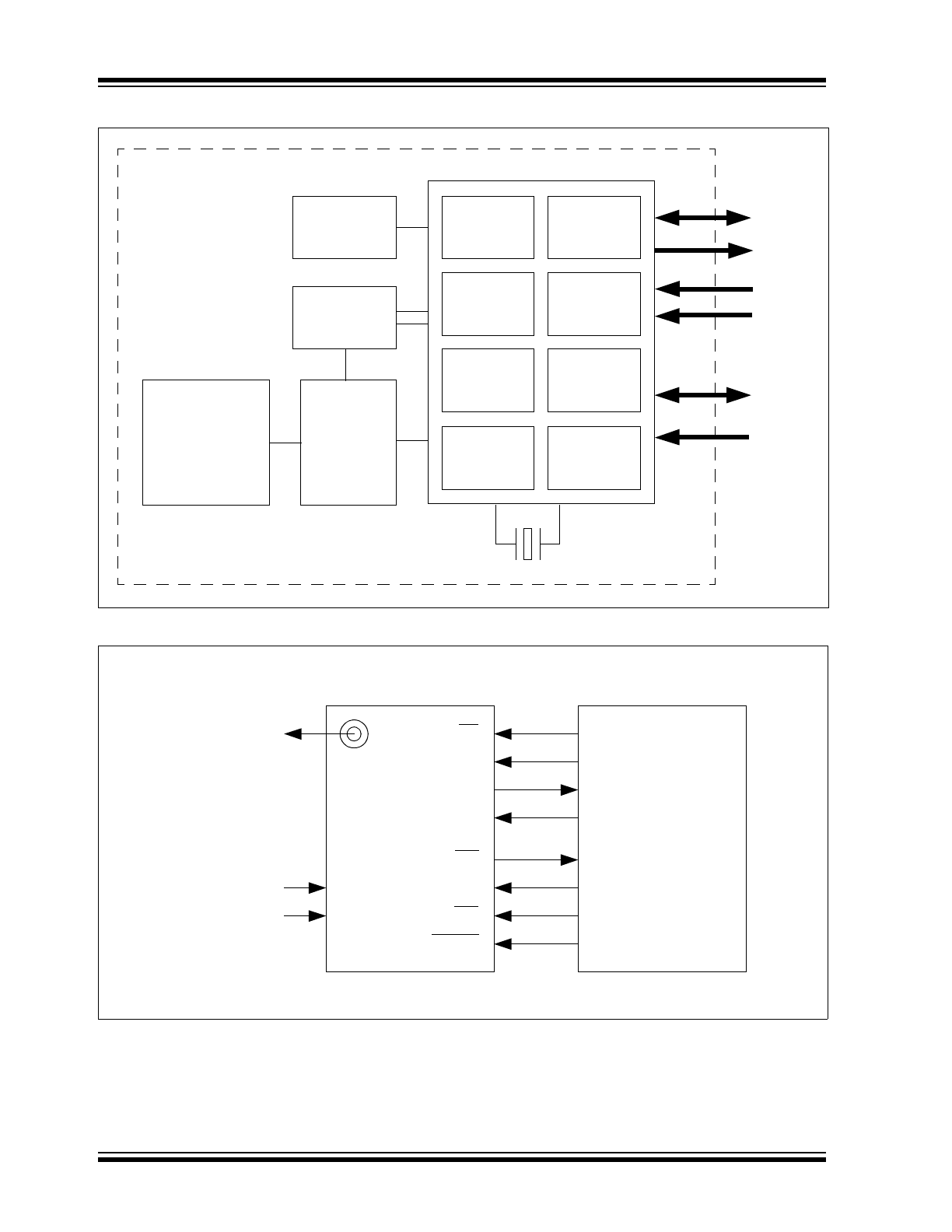
The block diagram in
Figure 1-1
represents a
MRF24WG0MA/MB module. It interfaces to Microchip
PIC18, PIC24, dsPIC33, or PIC32 microcontrollers
through a four-wire serial slave SPI interface –
interrupt, hibernate, reset, power and ground signals.
The module runs on a single supply voltage of
nominally 3.3V. The serial trace port operates at 3.3V
and requires a level shifter for operation with RS-232
devices. This port provides a serial output of module
status messages and is helpful for debugging
purposes.
Figure 1-2
shows a simplified example
connection between a Microchip PIC
®
MCU and the
module.
Table 1-1
lists the pin descriptions.
Data communications with the MRF24WG0MA/MB are
through the SPI interface that is detailed in Section 2.0
“Circuit Description”. The Microchip PIC microcon-
troller communicates with the module through a com-
mand API from within the Microchip TCP/IP stack. The
command API is detailed in the Microchip TCP/IP stack
online Help that is included in the free Microchip
Application Libraries download.
MRF24WG0MA/MB
DS70686B-page 6
Preliminary Information
2012 Microchip Technology Inc.
FIGURE 1-1:
MRF24WG0MA/MB BLOCK DIAGRAM
FIGURE 1-2:
MICROCONTROLLER TO MRF24WG0MA/MB INTERFACE
Slave SPI
Power
Encryption
Interface
802.1x (EAP)
Accelerator
RAM
ROM
SPI Flash
Interrupt
Trace
Reset
Hibernate
Matching
Circuitry
Antenna
PHY
IEEE 802.11b/g
WPA Engine
AES, TKIP
MRF24WG0MA/MB 2.4 GHz IEEE 802.11b/g Module
MRF24WG0MA
PCB
Internal
MAC/LLC
IEEE 802.11b/g
2.4 GHz
Transceiver/PA
Regulators
PIC
®
Microcontroller
MRF24WG0Mx
GND
VDD
External Antenna
(MRF24WG0MB)
I/O
CS
SDO
SDI
SCK
SDI
SDO
SCK
INTx
INT
I/O
HIBERNATE
I/O
WP
I/O
RESET
+3.3V (Typ)
GND

2012 Microchip Technology Inc.
Preliminary Information
DS70686B-page 7
MRF24WG0MA/MB
TABLE 1-1:
Pin Description
Pin
Symbol
Type
Description
1
GND
P
Ground
2
NC*
NC*
No connect
(3)
3
NC*
NC*
No connect
(3)
4
NC*
NC*
No connect
(4)
5
NC*
NC*
No connect
(3)
6
NC*
NC*
No connect
(3)
7
RESET
I: Constant
(1)
Module Reset input
8
NC
NC
Do not connect
9
NC*
NC*
No connect
(3)
10
GND
P
Ground
11
NC
NC
Do not connect
12
NC
NC
Do not connect
13
NC
NC
Do not connect
14
NC
NC
Do not connect
15
NC
NC
Do not connect
16
WP
(2)
I
Write protect (this pin is used to enable FLASH update)
17
V
DD
P
Power
18
GND
P
Ground
19
GND
P
Ground
20
HIBERNATE
I
Hibernate mode enable (high input will disable the module)
21
NC*
NC*
No connect
(3)
22
NC
NC
Do not connect
23
CS
I: Constant
(1)
SPI Chip Select input, constant drive or pull-up required
24
NC
NC
Do not connect
25
GND
P
Ground
26
DEBUG
RX
I
Serial debug port input (see Section 2.0 “Circuit Description”)
27
DEBUG
TX
O
Serial debug port output (see Section 2.0 “Circuit Description”)
28
GND
P
Ground
29
V
DD
P
Power
30
GND
P
Ground
31
NC
NC
Do not connect
32
SDO
O
SPI data out
33
INT
O
Interrupt output (open drain – requires a pull-up)
34
SCK
I
SPI clock input
35
SDI
I
SPI data in
36
GND
P
Ground
Legend: Pin type abbreviation: P = Power Input, I = Input, O = Output, NC = Do Not Connect, NC* = No Connect
Note 1:
Signals of Type “I: Constant” must either be constantly driven by the host or have a pull-up or pull-down (in
case the host is likely to tri-state the signal during power down modes). The constant drive is used to
ensure defined operation of the part and to minimize leakage current during low power modes.
2:
WP is used as write-protect for the internal module SPI Flash. For production use, this pin should be
pulled low. This pin can be controlled by the host microcontroller to enable in field Flash updates.
3:
Signals of Type “NC*” were JTAG function pins on previous family devices. Signals on these pins will have
no functional affect and will not impact the operation of this device.
4:
This signal should be left floating or pulled high only to support lowest 802.11PS power mode.
MRF24WG0MA/MB
DS70686B-page 8
Preliminary Information
2012 Microchip Technology Inc.
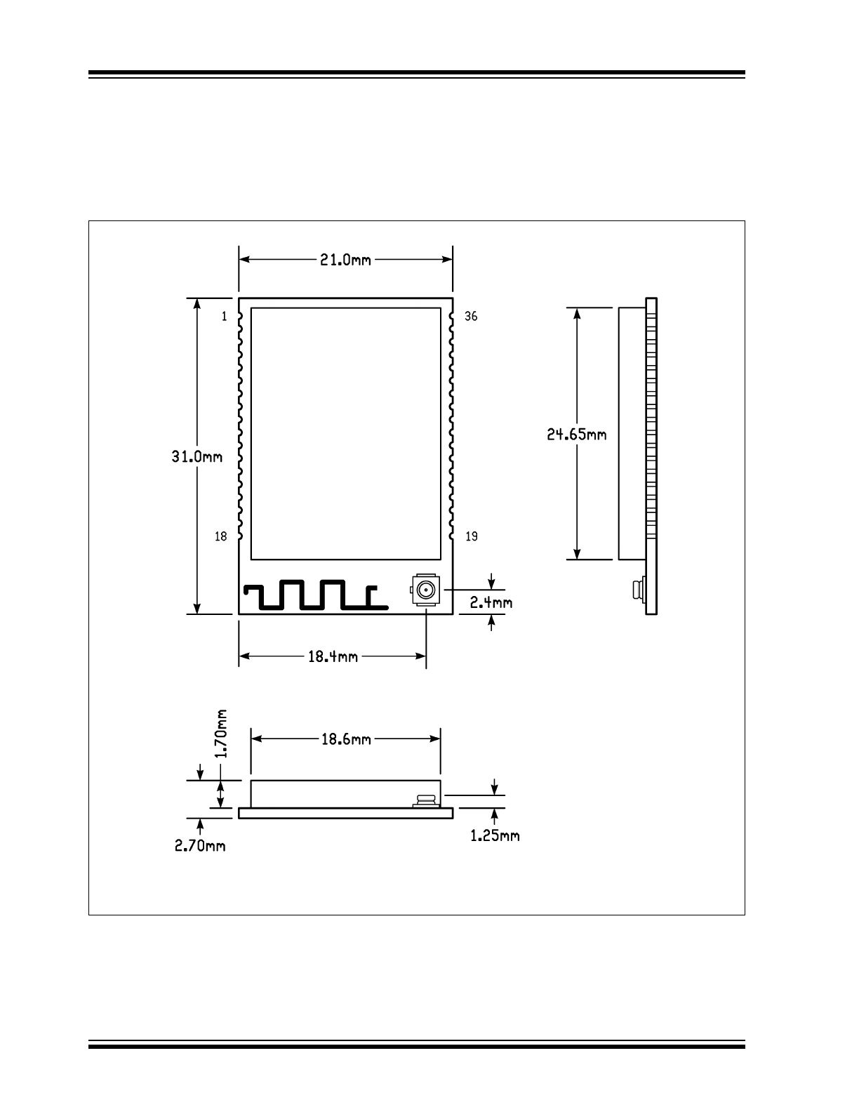
1.2
Mounting Details
The MRF24WG0MA/MB is a surface mountable mod-
ule. Module dimensions are shown in
Figure 1-3
. The
module Printed Circuit Board (PCB) is 1 mm thick with
castellated mounting points on two sides.
FIGURE 1-3:
MRF24WG0MA/MB MODULE PHYSICAL DIMENSIONS
Note:
Antenna connector on MRF24WG0MB only.
2012 Microchip Technology Inc.
Preliminary Information
DS70686B-page 9
MRF24WG0MA/MB
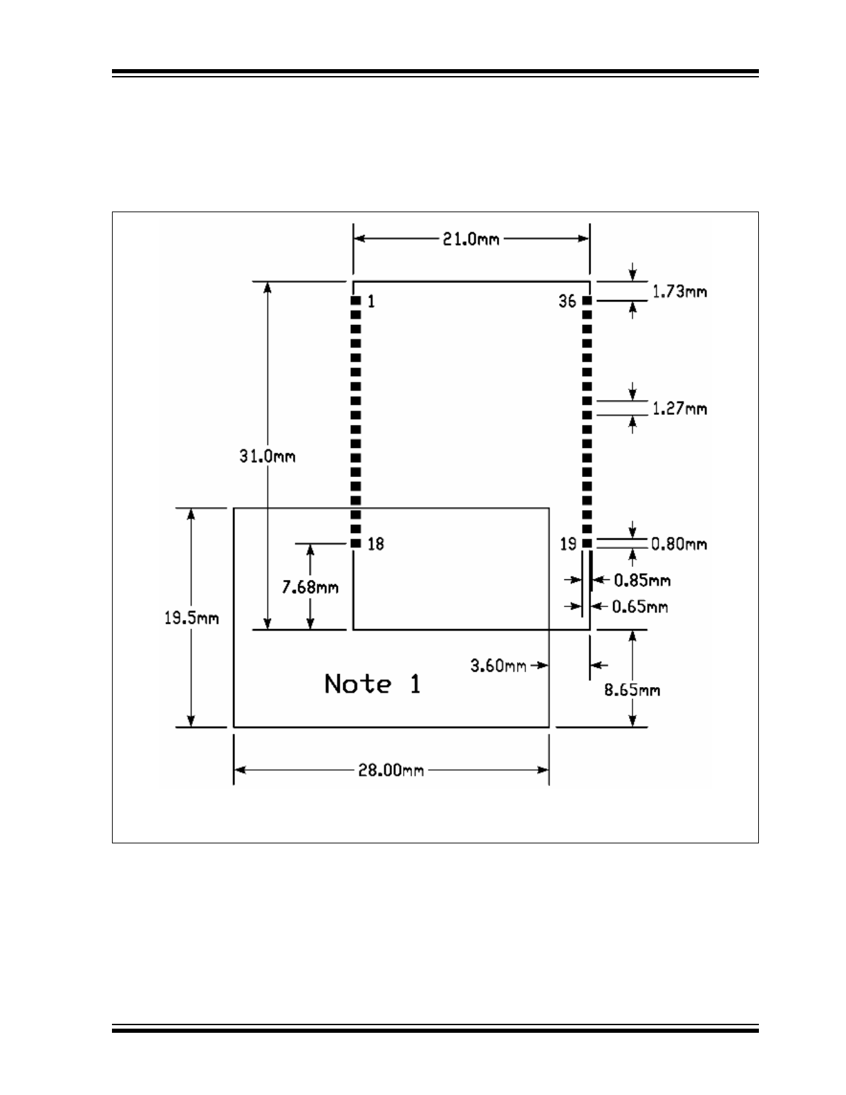
Figure 1-4
shows the recommended host PCB footprint
for the module.
The MRF24WG0MA has an integrated PCB antenna.
For best performance, follow the mounting details
shown in
Figure 1-4
.
For best performance, mount the module on the PCB
without metal obstructions in the keep out area of
Figure 1-4
. The antenna is tuned to have FR4 PCB
material underneath the module. Do not “cut-out” host
PCB material under the antenna.
FIGURE 1-4:
RECOMMENDED HOST PCB FOOTPRINT
Note 1: The “Note 1” demarcation specifies the host PCB copper plane keep-out area on underlying
board layers. It is permissible to route surface escape traces in this area.
MRF24WG0MA/MB
DS70686B-page 10
Preliminary Information
2012 Microchip Technology Inc.
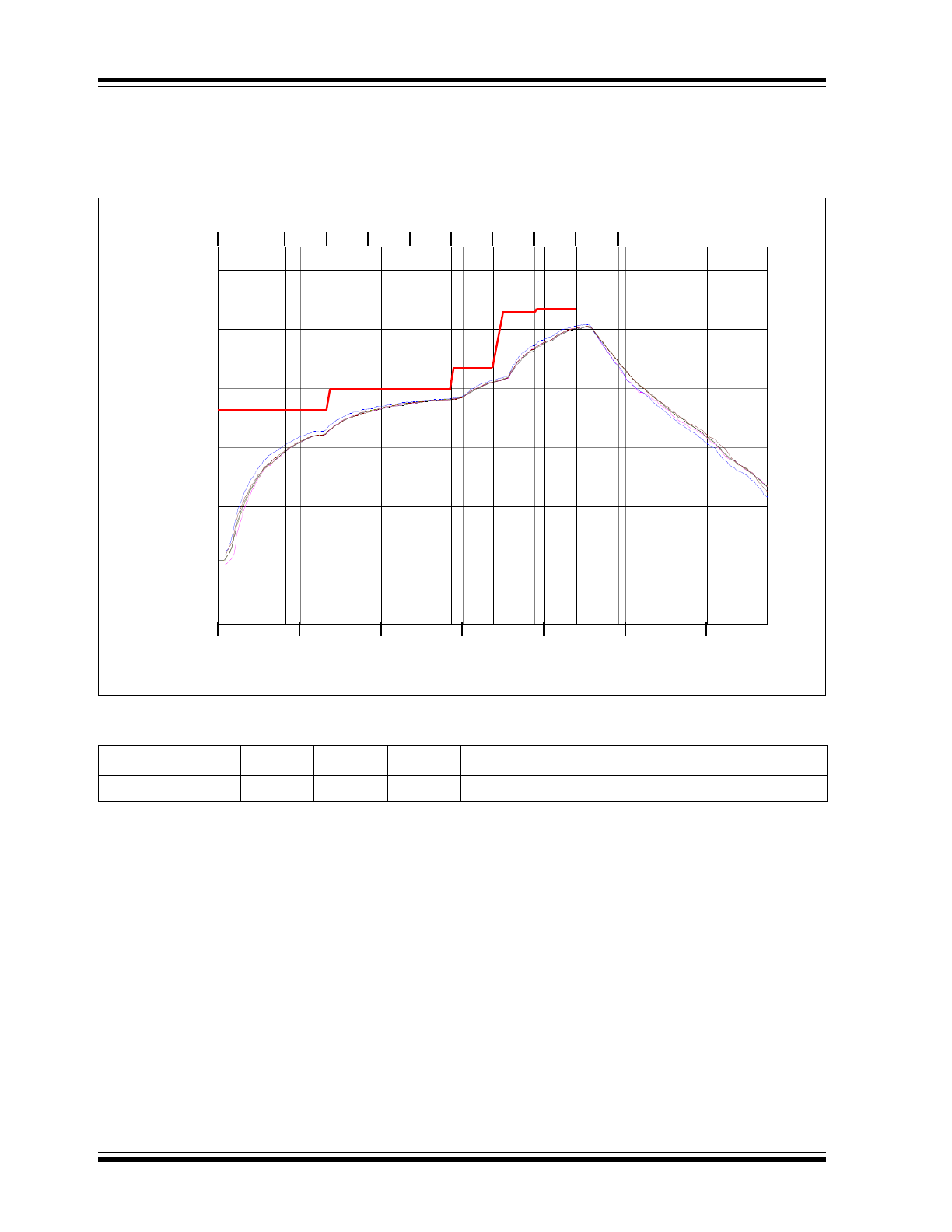
Figure 1-5
illustrates the module reflow profile that is
recommended for mounting the device onto the host
PCB.
FIGURE 1-5:
PRELIMINARY MODULE REFLOW PROFILE AND SETPOINTS
300
250
200
150
100
50
0
T
e
m
p
er
a
tu
re (
°C
)
Time (Seconds)
0
50
100
1
2
150
200
250
300
3
4
5
6
7
8
Zones
TABLE 1-2:
MODULE REFLOW PROFILE
(1)
Zone
1
2
3
4
5
6
7
8
Temperature (°C)
180°
180°
200°
200°
200°
220°
265°
270°
Note 1:
Conveyor Speed: 90 cm/min