

2015 - 2016 Microchip Technology Inc.
DS00001888B-page 1
Product Features
• High Performance 32-bit Embedded Controller
• Cost effective solution
• Small form factor ideal for embedded applications
• Low power; 13.25mA in active mode
• System in deep sleep consumes 70µA
• Host interface via I
2
C
• 3.3-Volt I/O
• Package
- 17mm x 17mm, 16-pin module
Sensor Firmware
• Sensor fusion firmware features include:
- Self-contained 9-axis sensor fusion
- Sensor data pass-through
- Fast in-use background calibration of all sen-
sors and calibration monitor
- Magnetic immunity: Enhanced magnetic dis-
tortion, detection and suppression
- Gyroscope drift cancellation
- Fully calibrated
• Easy to implement complete turnkey sensor
fusion solution
• Sensor power management
• Sensors Supported
- Bosch BMC150 Geomagnetic Sensor/Accel-
erometer
- Bosch BMG160 Gyroscope
Hardware Features
The hardware features in the MM7150 module include
the following:
• I
2
C Controller
- Supports I
2
C bus speeds to 400kHz
- Host Interface Supports Slave Operation
• Low Power Modes
Target Markets
• Internet of Things Applications
• Remote Controls, Gaming
• Fitness Monitoring
• Applications requiring data from an accelerome-
ter, magnetometer and gyroscope
Temperature Ranges Available
• Industrial (-40°C to +85°C)
• Commercial (0°C to +70°C)
Description
The MM7150 Motion Module is a simple, cost-effective
solution for integrating motion and positioning data into
a wide range of applications. The module contains the
SSC7150 motion coprocessor with integrated 9-axis
sensor fusion as well as high performance MEMS tech-
nology including a 3-axis accelerometer, gyroscope
and magnetometer. All components are integrated, cal-
ibrated and available on the module for PCB mounting.
MM7150
Motion Module

MM7150
DS00001888B-page 2
2015 - 2016 Microchip Technology Inc.
TO OUR VALUED CUSTOMERS
It is our intention to provide our valued customers with the best documentation possible to ensure successful use of
your Microchip products. To this end, we will continue to improve our publications to better suit your needs. Our pub-
lications will be refined and enhanced as new volumes and updates are introduced.
If you have any questions or comments regarding this publication, please contact the Marketing Communications
Department via E-mail at
docerrors@microchip.com
. We welcome your feedback.
Most Current Data Sheet
To obtain the most up-to-date version of this data sheet, please register at our Worldwide Web site at:
http://www.microchip.com
You can determine the version of a data sheet by examining its literature number found on the bottom outside corner
of any page. The last character of the literature number is the version number, (e.g., DS30000000A is version A of
document DS30000000).
Errata
An errata sheet, describing minor operational differences from the data sheet and recommended workarounds, may
exist for current devices. As device/documentation issues become known to us, we will publish an errata sheet. The
errata will specify the revision of silicon and revision of document to which it applies.
To determine if an errata sheet exists for a particular device, please check with one of the following:
• Microchip’s Worldwide Web site;
http://www.microchip.com
• Your local Microchip sales office (see last page)
When contacting a sales office, please specify which device, revision of silicon and data sheet (include -literature
number) you are using.
Customer Notification System
Register on our web site at
www.microchip.com
to receive the most current information on all of our products.

2015 - 2016 Microchip Technology Inc.
DS00001888B-page 3
MM7150
Table of Contents
1.0 MM7150 Pinout ............................................................................................................................................................................... 4
2.0 MM7150 Module ............................................................................................................................................................................. 7
3.0 MM7150 HID Functions .................................................................................................................................................................. 8
4.0 MM7150 Host Interface ................................................................................................................................................................. 12
5.0 MM7150 Firmware Update ........................................................................................................................................................... 13
6.0 MM7150 References ..................................................................................................................................................................... 14
7.0 MM7150 Performance .................................................................................................................................................................. 15
8.0 Electrical Characteristics ............................................................................................................................................................... 16
Appendix A: Revision History .............................................................................................................................................................. 24
The Microchip Web Site ...................................................................................................................................................................... 25
Customer Change Notification Service ............................................................................................................................................... 25
Customer Support ............................................................................................................................................................................... 25
Product Identification System ............................................................................................................................................................. 26
MM7150
DS00001888B-page 4
2015 - 2016 Microchip Technology Inc.
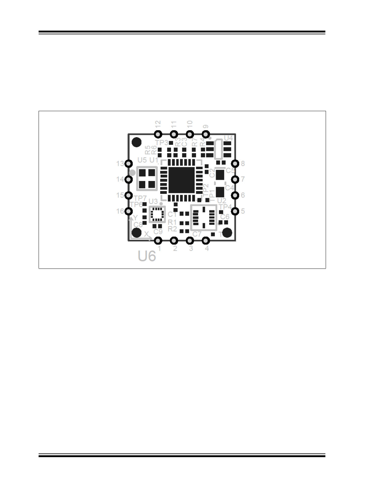
1.0
MM7150 PINOUT
The pinout of the MM7150 Motion
Module is shown in the assembly drawing.
1.1
Assembly Drawing
The assembly drawing is shown in
Figure 1-1
.
FIGURE 1-1:
ASSEMBLY DRAWING
2015 - 2016 Microchip Technology Inc.
DS00001888B-page 5
MM7150
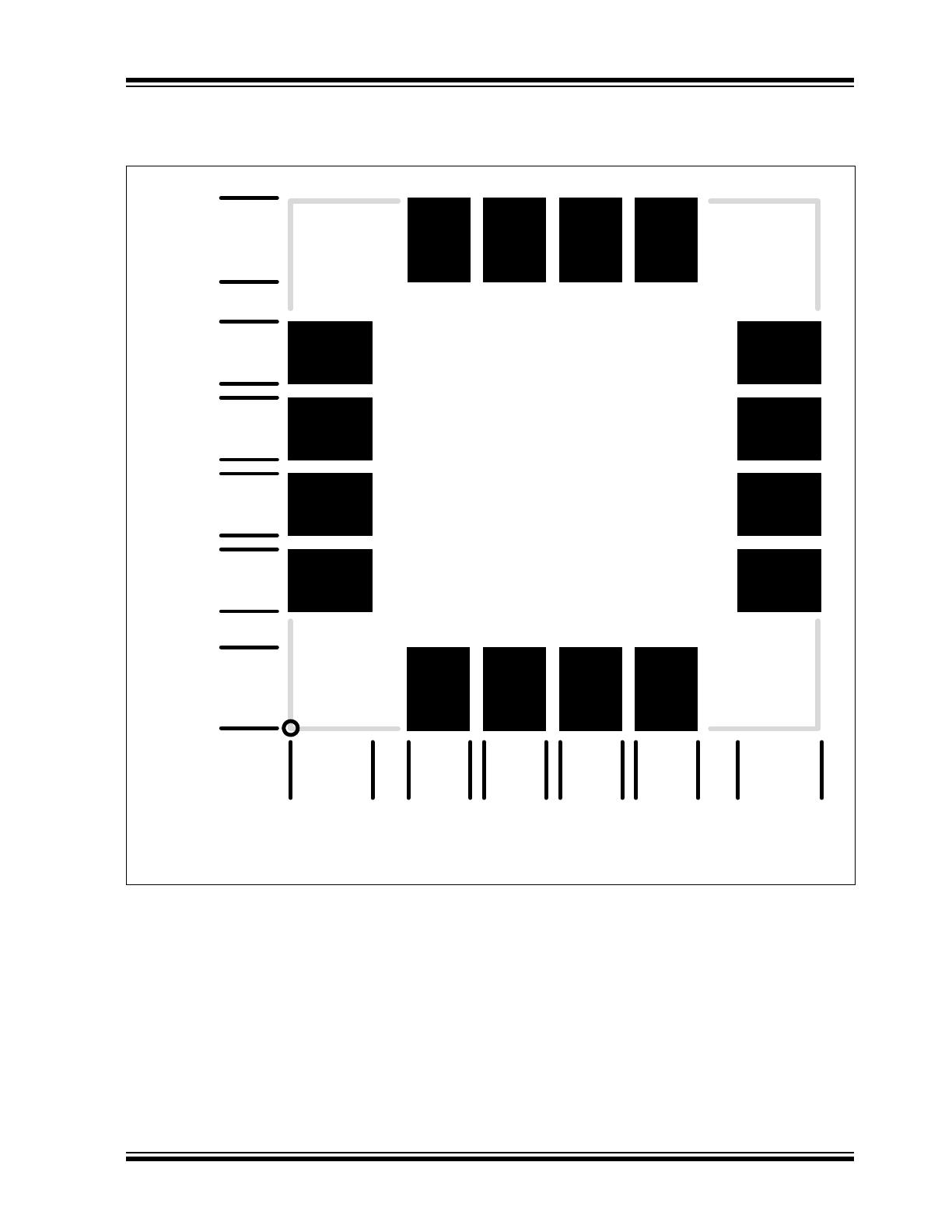
1.2
Recommended Land Pattern
0.00mm
1
16
2.80mm
4.00mm
6.08mm
6.53mm
8.61mm
9.08mm
11.16mm
11.62mm
13.70mm
15.04mm
17.84mm
0.0
0
mm
2.8
0
mm
4.0
0
mm
6.0
8
mm
6.5
3
mm
8.6
1
mm
9.0
8
mm
11
.1
6
m
m
11
.6
2
m
m
13
.7
0
m
m
15
.0
4
m
m
17
.8
4
m
m

MM7150
DS00001888B-page 6
2015 - 2016 Microchip Technology Inc.
1.3
Pin Descriptions
The pin descriptions are provided in
Table 1-1
.
TABLE 1-1:
PIN DESCRIPTIONS
Pin
Number
Name
Type
Description
1
HOST_TO_SH_WAKE
I
Used to wake Motion Module from a Sleep state. This signal must
be driven high at least 11ms prior to sending any I
2
C traffic to the
Motion Module. Active high input.
This pin should be connected to VDD through a 100KΩ
resistor.
11
HOST_TO_SH_RESET
I
Reset input. Used to reset the host I
2
C interface.
This pin should be connected to VDD through a 100KΩ
resistor.
4
HIDI2C_HOST_INT
O
Alert Interrupt signal from Motion Module to Host. Used to tell
Host data from Motion Module is ready to be sent out. Active low
output.
15
HIDI2C_HOST_CLK
IOD
I
2
C Controller Clock to Host Interface
16
HIDI2C_HOST_DAT
IOD
I
2
C Controller Data to Host Interface
10
NC1
-
This pin should be left unconnected
2
NC2
-
This pin should be left unconnected
9
NC3
-
This pin should be left unconnected
12
NC4
-
This pin should be left unconnected
13
NC5
-
This pin should be left unconnected
14
NC6
-
This pin should be left unconnected
3
NC7
-
This pin should be left unconnected
5
NC8
-
This pin should be left unconnected
6
NC9
-
This pin should be left unconnected
7
VDD
PWR
VDD supply
8
VSS
GND
VDD associated ground
2015 - 2016 Microchip Technology Inc.
DS00001888B-page 7
MM7150
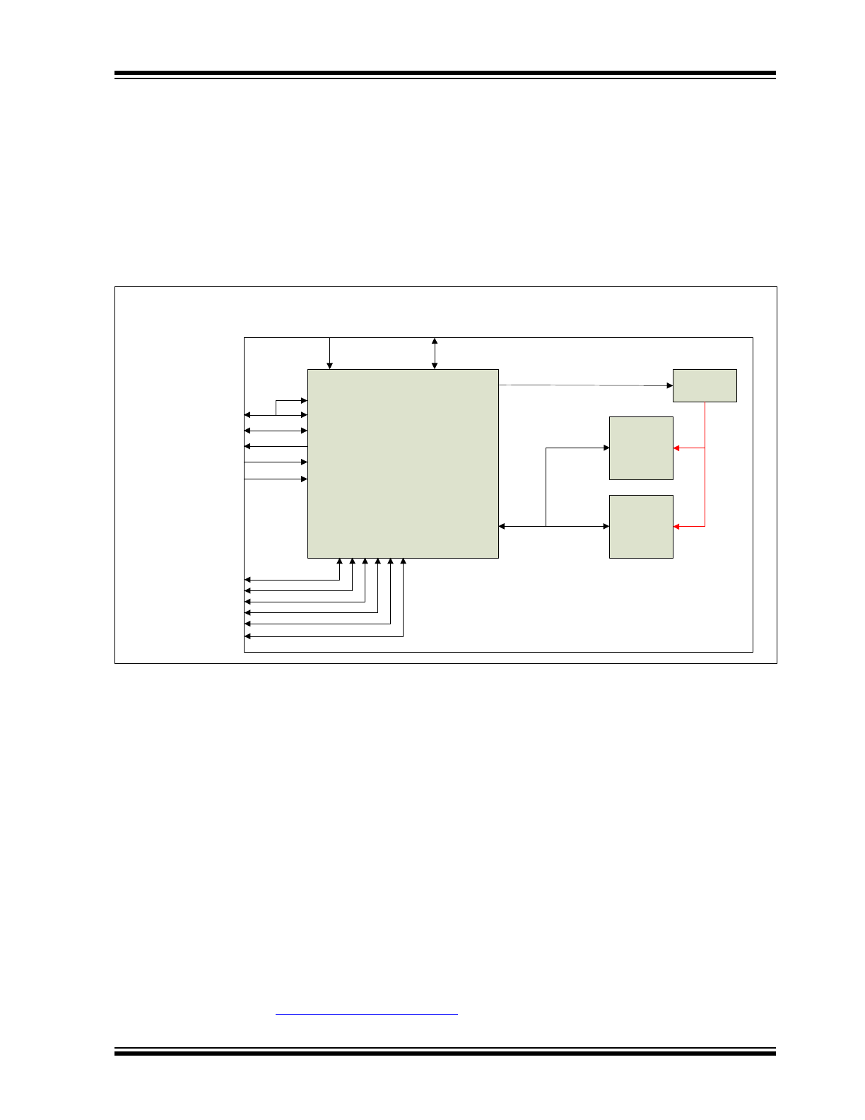
2.0
MM7150 MODULE
The MM7150 Motion Module provides 9-axis sensor fusion that includes a 3-axis accelerometer, a 3-axis gyroscope
and a 3-axis magnetometer. The module has an I
2
C interface to the host, and supports HID over I
2
C. The module
includes the Bosch BMC150 Geomagnetic Sensor/Accelerometer and Bosch BMG160 Gyroscope.
2.1
Module Block Diagram
The block diagram of the module is shown in
Figure 2-1
.
2.2
Module Features
The MM7150 Motion Module provides self-contained 9-axis sensor fusion. It supports fast in-use background calibration
of all sensors and calibration monitor. Magnetic immunity features provide enhanced magnetic distortion detection and
suppression. The module also provides gyroscope drift cancellation.
2.3
Calibration Requirements
User calibration is not required. The MM7150 Motion Module supports fast in-use background calibration of all sensors
and calibration monitor.
2.4
Other Information
To obtain the most recent and complete documentation for this module, including:
- User's Guide
- Board Description
- Board Schematics
- Source Code
- Application Examples
- Links to Web Seminars
Please refer to the web site:
www.microchip.com/motion
.
FIGURE 2-1:
MM7150 MODULE BLOCK DIAGRAM
Microchip
SSC7150
Motion Coprocessor
Bosch
BMG160
(Gyro)
Bosch
BMC150
(A+M)
TPS22929
Power Load
VSENSOR
HIDI2C_DEVICE_CLK
HIDI2C_DEVICE_DAT
HIDI2C_HOST_DAT
HIDI2C_HOST_CLK
HIDI2C_HOST_INT
HOST_TO_SH_WAKE
D2_WAKE_UP
+3
.3
V
GN
D
VDD
VSS (x2)
AVSS
HOST_TO_SH_RESET
NC1
NC2
NC3
NC4
NC5
NC6

MM7150
DS00001888B-page 8
2015 - 2016 Microchip Technology Inc.
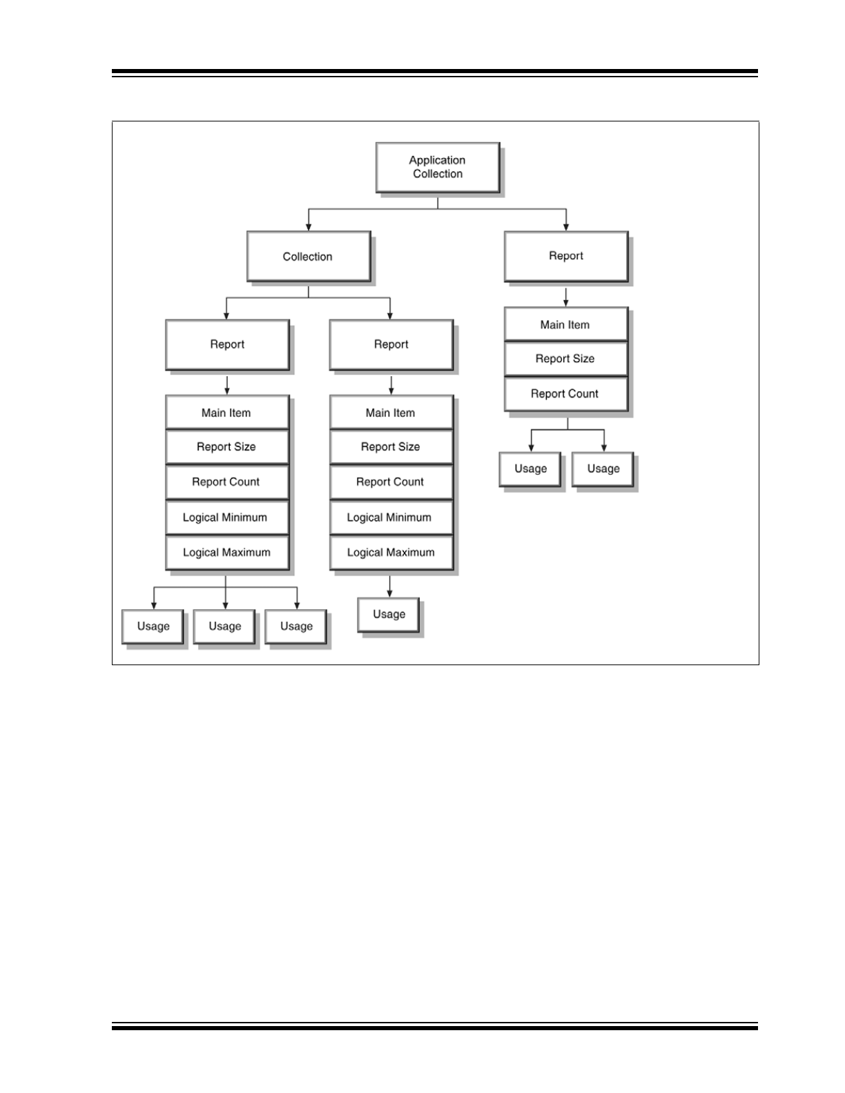
3.0
MM7150 HID FUNCTIONS
The MM7150 responds to the standard HID protocol for sensors when used over I
2
C, defined in References [
1
] and [
2
].
The hierarchy of descriptors used in the HID protocol is as follows:
The following sections described the descriptors required for communicating with the MM7150:
3.1
HID Descriptor
3.2
Report Descriptors
Report descriptors are composed of pieces of information. Each piece of information is called an Item.
The HID class driver contains a parser used to analyze items found in the Report descriptor. The parser extracts infor-
mation from the descriptor in a linear fashion.
The parser collects the state of each known item as it walks through the descriptor, and stores them in an item state
table. The item state table contains the state of individual items. From the parser's point of view, a HID class device looks
like the following.
TABLE 3-1:
HID DESCRIPTOR FORMAT (I
2
C)
Field
Description
Size
Value
wHIDDescLength
Length of HID Descriptor
UINT 16
0x001E
bcdVersion
Version compliance. Compliant with Version 1.00
UINT 16
0x0100
wReportDescLength
Report Descriptor Length (3213 bytes)
UINT 16
0x0C8D
wReportDescRegister
Identifier to read Report Descriptor
UINT 16
0x0002
wInputRegister
Identifier to read Input Report
UINT 16
0x0003
wMaxInputLength
Input Report is 13 Bytes + 2 Bytes length field
UINT 16
0x000D
wOutputRegistert
Identifier to read Output Report
UINT 16
0x0000
wMaxOutputLength
No Output Report
UINT 16
0x0000
wCommandRegister
Identifier for Command Register
UINT 16
0x0005
wDataRegister
Identifier for Data Register
UINT 16
0x0006
wVendorID
Vendor ID
UINT 16
0x04D8
wProductID
Product ID
UINT 16
0x0F01
wVersionID
Version
UINT 16
0x7150
RESERVED
Reserved
UINT 32
0x0
2015 - 2016 Microchip Technology Inc.
DS00001888B-page 9
MM7150
The Report descriptor is unlike other descriptors in that it is not simply a table of values. The length and content of a
Report descriptor vary depending on the number of data fields required for the device’s report or reports. The Report
descriptor is made up of items that provide information about the device.
The HID report for each sensor has two sections Feature Report and Input Report. The feature report for all the sen-
sors is same. The following sections describe the Feature Report and all Input Reports returned by the Motion Module.

MM7150
DS00001888B-page 10
2015 - 2016 Microchip Technology Inc.
3.2.1
FEATURE REPORT
3.2.2
3D ACCELEROMETER INPUT REPORT
3.2.3
COMPASS INPUT REPORT
TABLE 3-2:
FEATURE REPORT FORMAT
Field
Description
Size
ucReportID
Report ID
UINT 8
ucConnectionType
Connection Type
UINT 8
ucReportingState
Reporting State
UINT 8
ucPowerState
Power On State
UINT 8
ucSensorState
Sensor State
UINT 8
uIReportInterval
Reporting Interval
UINT 16
usAccuracy
Accuracy
UINT 16
usResolution
Resolution
UINT 16
usChangeSensitivity
Change Sensitivity
UINT 16
sMaximum
Maximum range
INT 16
sMinimum
Minimum range
INT 16
minimumReportInterval
Minimum report interval supported
UINT16
sensorDesc[6]
Sensor description, initialized “MCHPSF”
INT16
TABLE 3-3:
3D ACCELEROMETER REPORT FORMAT
Field
Description
Size
ucReportID
Report ID
UINT 8
ucSensorState
Sensor State
UINT 8
ucEventType
Event Type
UINT 8
sAccelXValue
Accelerometer X axis value
INT 16
sAccelYValue
Accelerometer Y axis value
INT 16
sAccelZValue
Accelerometer Z axis value
INT 16
ucShakeDetectState
Shake event detection
UINT 8
TABLE 3-4:
COMPASS REPORT FORMAT
Field
Description
Size
ucReportID
Report ID
UINT 8
ucSensorState
Sensor State
UINT 8
ucEventType
Event Type
UINT 8
sHeadingCompensatedMag-
neticNorthValue
Magnetic north value
INT 16
sFluxXValue
Magnetic field strength, X axis value
INT16
sFluxYValue
Magnetic field strength, Y axis value
INT16
sFluxZValue
Magnetic field strength, Z axis value
INT16
2015 - 2016 Microchip Technology Inc.
DS00001888B-page 1
Product Features
• High Performance 32-bit Embedded Controller
• Cost effective solution
• Small form factor ideal for embedded applications
• Low power; 13.25mA in active mode
• System in deep sleep consumes 70µA
• Host interface via I
2
C
• 3.3-Volt I/O
• Package
- 17mm x 17mm, 16-pin module
Sensor Firmware
• Sensor fusion firmware features include:
- Self-contained 9-axis sensor fusion
- Sensor data pass-through
- Fast in-use background calibration of all sen-
sors and calibration monitor
- Magnetic immunity: Enhanced magnetic dis-
tortion, detection and suppression
- Gyroscope drift cancellation
- Fully calibrated
• Easy to implement complete turnkey sensor
fusion solution
• Sensor power management
• Sensors Supported
- Bosch BMC150 Geomagnetic Sensor/Accel-
erometer
- Bosch BMG160 Gyroscope
Hardware Features
The hardware features in the MM7150 module include
the following:
• I
2
C Controller
- Supports I
2
C bus speeds to 400kHz
- Host Interface Supports Slave Operation
• Low Power Modes
Target Markets
• Internet of Things Applications
• Remote Controls, Gaming
• Fitness Monitoring
• Applications requiring data from an accelerome-
ter, magnetometer and gyroscope
Temperature Ranges Available
• Industrial (-40°C to +85°C)
• Commercial (0°C to +70°C)
Description
The MM7150 Motion Module is a simple, cost-effective
solution for integrating motion and positioning data into
a wide range of applications. The module contains the
SSC7150 motion coprocessor with integrated 9-axis
sensor fusion as well as high performance MEMS tech-
nology including a 3-axis accelerometer, gyroscope
and magnetometer. All components are integrated, cal-
ibrated and available on the module for PCB mounting.
MM7150
Motion Module
MM7150
DS00001888B-page 2
2015 - 2016 Microchip Technology Inc.
TO OUR VALUED CUSTOMERS
It is our intention to provide our valued customers with the best documentation possible to ensure successful use of
your Microchip products. To this end, we will continue to improve our publications to better suit your needs. Our pub-
lications will be refined and enhanced as new volumes and updates are introduced.
If you have any questions or comments regarding this publication, please contact the Marketing Communications
Department via E-mail at
docerrors@microchip.com
. We welcome your feedback.
Most Current Data Sheet
To obtain the most up-to-date version of this data sheet, please register at our Worldwide Web site at:
http://www.microchip.com
You can determine the version of a data sheet by examining its literature number found on the bottom outside corner
of any page. The last character of the literature number is the version number, (e.g., DS30000000A is version A of
document DS30000000).
Errata
An errata sheet, describing minor operational differences from the data sheet and recommended workarounds, may
exist for current devices. As device/documentation issues become known to us, we will publish an errata sheet. The
errata will specify the revision of silicon and revision of document to which it applies.
To determine if an errata sheet exists for a particular device, please check with one of the following:
• Microchip’s Worldwide Web site;
http://www.microchip.com
• Your local Microchip sales office (see last page)
When contacting a sales office, please specify which device, revision of silicon and data sheet (include -literature
number) you are using.
Customer Notification System
Register on our web site at
www.microchip.com
to receive the most current information on all of our products.
2015 - 2016 Microchip Technology Inc.
DS00001888B-page 3
MM7150
Table of Contents
1.0 MM7150 Pinout ............................................................................................................................................................................... 4
2.0 MM7150 Module ............................................................................................................................................................................. 7
3.0 MM7150 HID Functions .................................................................................................................................................................. 8
4.0 MM7150 Host Interface ................................................................................................................................................................. 12
5.0 MM7150 Firmware Update ........................................................................................................................................................... 13
6.0 MM7150 References ..................................................................................................................................................................... 14
7.0 MM7150 Performance .................................................................................................................................................................. 15
8.0 Electrical Characteristics ............................................................................................................................................................... 16
Appendix A: Revision History .............................................................................................................................................................. 24
The Microchip Web Site ...................................................................................................................................................................... 25
Customer Change Notification Service ............................................................................................................................................... 25
Customer Support ............................................................................................................................................................................... 25
Product Identification System ............................................................................................................................................................. 26
MM7150
DS00001888B-page 4
2015 - 2016 Microchip Technology Inc.
1.0
MM7150 PINOUT
The pinout of the MM7150 Motion
Module is shown in the assembly drawing.
1.1
Assembly Drawing
The assembly drawing is shown in
Figure 1-1
.
FIGURE 1-1:
ASSEMBLY DRAWING
2015 - 2016 Microchip Technology Inc.
DS00001888B-page 5
MM7150
1.2
Recommended Land Pattern
0.00mm
1
16
2.80mm
4.00mm
6.08mm
6.53mm
8.61mm
9.08mm
11.16mm
11.62mm
13.70mm
15.04mm
17.84mm
0.0
0
mm
2.8
0
mm
4.0
0
mm
6.0
8
mm
6.5
3
mm
8.6
1
mm
9.0
8
mm
11
.1
6
m
m
11
.6
2
m
m
13
.7
0
m
m
15
.0
4
m
m
17
.8
4
m
m
MM7150
DS00001888B-page 6
2015 - 2016 Microchip Technology Inc.
1.3
Pin Descriptions
The pin descriptions are provided in
Table 1-1
.
TABLE 1-1:
PIN DESCRIPTIONS
Pin
Number
Name
Type
Description
1
HOST_TO_SH_WAKE
I
Used to wake Motion Module from a Sleep state. This signal must
be driven high at least 11ms prior to sending any I
2
C traffic to the
Motion Module. Active high input.
This pin should be connected to VDD through a 100KΩ
resistor.
11
HOST_TO_SH_RESET
I
Reset input. Used to reset the host I
2
C interface.
This pin should be connected to VDD through a 100KΩ
resistor.
4
HIDI2C_HOST_INT
O
Alert Interrupt signal from Motion Module to Host. Used to tell
Host data from Motion Module is ready to be sent out. Active low
output.
15
HIDI2C_HOST_CLK
IOD
I
2
C Controller Clock to Host Interface
16
HIDI2C_HOST_DAT
IOD
I
2
C Controller Data to Host Interface
10
NC1
-
This pin should be left unconnected
2
NC2
-
This pin should be left unconnected
9
NC3
-
This pin should be left unconnected
12
NC4
-
This pin should be left unconnected
13
NC5
-
This pin should be left unconnected
14
NC6
-
This pin should be left unconnected
3
NC7
-
This pin should be left unconnected
5
NC8
-
This pin should be left unconnected
6
NC9
-
This pin should be left unconnected
7
VDD
PWR
VDD supply
8
VSS
GND
VDD associated ground
2015 - 2016 Microchip Technology Inc.
DS00001888B-page 7
MM7150
2.0
MM7150 MODULE
The MM7150 Motion Module provides 9-axis sensor fusion that includes a 3-axis accelerometer, a 3-axis gyroscope
and a 3-axis magnetometer. The module has an I
2
C interface to the host, and supports HID over I
2
C. The module
includes the Bosch BMC150 Geomagnetic Sensor/Accelerometer and Bosch BMG160 Gyroscope.
2.1
Module Block Diagram
The block diagram of the module is shown in
Figure 2-1
.
2.2
Module Features
The MM7150 Motion Module provides self-contained 9-axis sensor fusion. It supports fast in-use background calibration
of all sensors and calibration monitor. Magnetic immunity features provide enhanced magnetic distortion detection and
suppression. The module also provides gyroscope drift cancellation.
2.3
Calibration Requirements
User calibration is not required. The MM7150 Motion Module supports fast in-use background calibration of all sensors
and calibration monitor.
2.4
Other Information
To obtain the most recent and complete documentation for this module, including:
- User's Guide
- Board Description
- Board Schematics
- Source Code
- Application Examples
- Links to Web Seminars
Please refer to the web site:
www.microchip.com/motion
.
FIGURE 2-1:
MM7150 MODULE BLOCK DIAGRAM
Microchip
SSC7150
Motion Coprocessor
Bosch
BMG160
(Gyro)
Bosch
BMC150
(A+M)
TPS22929
Power Load
VSENSOR
HIDI2C_DEVICE_CLK
HIDI2C_DEVICE_DAT
HIDI2C_HOST_DAT
HIDI2C_HOST_CLK
HIDI2C_HOST_INT
HOST_TO_SH_WAKE
D2_WAKE_UP
+3
.3
V
GN
D
VDD
VSS (x2)
AVSS
HOST_TO_SH_RESET
NC1
NC2
NC3
NC4
NC5
NC6
MM7150
DS00001888B-page 8
2015 - 2016 Microchip Technology Inc.
3.0
MM7150 HID FUNCTIONS
The MM7150 responds to the standard HID protocol for sensors when used over I
2
C, defined in References [
1
] and [
2
].
The hierarchy of descriptors used in the HID protocol is as follows:
The following sections described the descriptors required for communicating with the MM7150:
3.1
HID Descriptor
3.2
Report Descriptors
Report descriptors are composed of pieces of information. Each piece of information is called an Item.
The HID class driver contains a parser used to analyze items found in the Report descriptor. The parser extracts infor-
mation from the descriptor in a linear fashion.
The parser collects the state of each known item as it walks through the descriptor, and stores them in an item state
table. The item state table contains the state of individual items. From the parser's point of view, a HID class device looks
like the following.
TABLE 3-1:
HID DESCRIPTOR FORMAT (I
2
C)
Field
Description
Size
Value
wHIDDescLength
Length of HID Descriptor
UINT 16
0x001E
bcdVersion
Version compliance. Compliant with Version 1.00
UINT 16
0x0100
wReportDescLength
Report Descriptor Length (3213 bytes)
UINT 16
0x0C8D
wReportDescRegister
Identifier to read Report Descriptor
UINT 16
0x0002
wInputRegister
Identifier to read Input Report
UINT 16
0x0003
wMaxInputLength
Input Report is 13 Bytes + 2 Bytes length field
UINT 16
0x000D
wOutputRegistert
Identifier to read Output Report
UINT 16
0x0000
wMaxOutputLength
No Output Report
UINT 16
0x0000
wCommandRegister
Identifier for Command Register
UINT 16
0x0005
wDataRegister
Identifier for Data Register
UINT 16
0x0006
wVendorID
Vendor ID
UINT 16
0x04D8
wProductID
Product ID
UINT 16
0x0F01
wVersionID
Version
UINT 16
0x7150
RESERVED
Reserved
UINT 32
0x0
2015 - 2016 Microchip Technology Inc.
DS00001888B-page 9
MM7150
The Report descriptor is unlike other descriptors in that it is not simply a table of values. The length and content of a
Report descriptor vary depending on the number of data fields required for the device’s report or reports. The Report
descriptor is made up of items that provide information about the device.
The HID report for each sensor has two sections Feature Report and Input Report. The feature report for all the sen-
sors is same. The following sections describe the Feature Report and all Input Reports returned by the Motion Module.
MM7150
DS00001888B-page 10
2015 - 2016 Microchip Technology Inc.
3.2.1
FEATURE REPORT
3.2.2
3D ACCELEROMETER INPUT REPORT
3.2.3
COMPASS INPUT REPORT
TABLE 3-2:
FEATURE REPORT FORMAT
Field
Description
Size
ucReportID
Report ID
UINT 8
ucConnectionType
Connection Type
UINT 8
ucReportingState
Reporting State
UINT 8
ucPowerState
Power On State
UINT 8
ucSensorState
Sensor State
UINT 8
uIReportInterval
Reporting Interval
UINT 16
usAccuracy
Accuracy
UINT 16
usResolution
Resolution
UINT 16
usChangeSensitivity
Change Sensitivity
UINT 16
sMaximum
Maximum range
INT 16
sMinimum
Minimum range
INT 16
minimumReportInterval
Minimum report interval supported
UINT16
sensorDesc[6]
Sensor description, initialized “MCHPSF”
INT16
TABLE 3-3:
3D ACCELEROMETER REPORT FORMAT
Field
Description
Size
ucReportID
Report ID
UINT 8
ucSensorState
Sensor State
UINT 8
ucEventType
Event Type
UINT 8
sAccelXValue
Accelerometer X axis value
INT 16
sAccelYValue
Accelerometer Y axis value
INT 16
sAccelZValue
Accelerometer Z axis value
INT 16
ucShakeDetectState
Shake event detection
UINT 8
TABLE 3-4:
COMPASS REPORT FORMAT
Field
Description
Size
ucReportID
Report ID
UINT 8
ucSensorState
Sensor State
UINT 8
ucEventType
Event Type
UINT 8
sHeadingCompensatedMag-
neticNorthValue
Magnetic north value
INT 16
sFluxXValue
Magnetic field strength, X axis value
INT16
sFluxYValue
Magnetic field strength, Y axis value
INT16
sFluxZValue
Magnetic field strength, Z axis value
INT16