
© 2011 Microchip Technology Inc.
DS51932B
MCP47X6
PICtail™ Plus
Daughter Board
User’s Guide
DS51932B-page 2
© 2011 Microchip Technology Inc.
Information contained in this publication regarding device
applications and the like is provided only for your convenience
and may be superseded by updates. It is your responsibility to
ensure that your application meets with your specifications.
MICROCHIP MAKES NO REPRESENTATIONS OR
WARRANTIES OF ANY KIND WHETHER EXPRESS OR
IMPLIED, WRITTEN OR ORAL, STATUTORY OR
OTHERWISE, RELATED TO THE INFORMATION,
INCLUDING BUT NOT LIMITED TO ITS CONDITION,
QUALITY, PERFORMANCE, MERCHANTABILITY OR
FITNESS FOR PURPOSE. Microchip disclaims all liability
arising from this information and its use. Use of Microchip
devices in life support and/or safety applications is entirely at
the buyer’s risk, and the buyer agrees to defend, indemnify and
hold harmless Microchip from any and all damages, claims,
suits, or expenses resulting from such use. No licenses are
conveyed, implicitly or otherwise, under any Microchip
intellectual property rights.
Trademarks
The Microchip name and logo, the Microchip logo, dsPIC,
K
EE
L
OQ
, K
EE
L
OQ
logo, MPLAB, PIC, PICmicro, PICSTART,
PIC
32
logo, rfPIC and UNI/O are registered trademarks of
Microchip Technology Incorporated in the U.S.A. and other
countries.
FilterLab, Hampshire, HI-TECH C, Linear Active Thermistor,
MXDEV, MXLAB, SEEVAL and The Embedded Control
Solutions Company are registered trademarks of Microchip
Technology Incorporated in the U.S.A.
Analog-for-the-Digital Age, Application Maestro, chipKIT,
chipKIT logo, CodeGuard, dsPICDEM, dsPICDEM.net,
dsPICworks, dsSPEAK, ECAN, ECONOMONITOR,
FanSense, HI-TIDE, In-Circuit Serial Programming, ICSP,
Mindi, MiWi, MPASM, MPLAB Certified logo, MPLIB,
MPLINK, mTouch, Omniscient Code Generation, PICC,
PICC-18, PICDEM, PICDEM.net, PICkit, PICtail, REAL ICE,
rfLAB, Select Mode, Total Endurance, TSHARC,
UniWinDriver, WiperLock and ZENA are trademarks of
Microchip Technology Incorporated in the U.S.A. and other
countries.
SQTP is a service mark of Microchip Technology Incorporated
in the U.S.A.
All other trademarks mentioned herein are property of their
respective companies.
© 2011, Microchip Technology Incorporated, Printed in the
U.S.A., All Rights Reserved.
Printed on recycled paper.
ISBN: 978-1-61341-709-6
Note the following details of the code protection feature on Microchip devices:
•
Microchip products meet the specification contained in their particular Microchip Data Sheet.
•
Microchip believes that its family of products is one of the most secure families of its kind on the market today, when used in the
intended manner and under normal conditions.
•
There are dishonest and possibly illegal methods used to breach the code protection feature. All of these methods, to our
knowledge, require using the Microchip products in a manner outside the operating specifications contained in Microchip’s Data
Sheets. Most likely, the person doing so is engaged in theft of intellectual property.
•
Microchip is willing to work with the customer who is concerned about the integrity of their code.
•
Neither Microchip nor any other semiconductor manufacturer can guarantee the security of their code. Code protection does not
mean that we are guaranteeing the product as “unbreakable.”
Code protection is constantly evolving. We at Microchip are committed to continuously improving the code protection features of our
products. Attempts to break Microchip’s code protection feature may be a violation of the Digital Millennium Copyright Act. If such acts
allow unauthorized access to your software or other copyrighted work, you may have a right to sue for relief under that Act.
Microchip received ISO/TS-16949:2009 certification for its worldwide
headquarters, design and wafer fabrication facilities in Chandler and
Tempe, Arizona; Gresham, Oregon and design centers in California
and India. The Company’s quality system processes and procedures
are for its PIC
®
MCUs and dsPIC
®
DSCs, K
EE
L
OQ
®
code hopping
devices, Serial EEPROMs, microperipherals, nonvolatile memory and
analog products. In addition, Microchip’s quality system for the design
and manufacture of development systems is ISO 9001:2000 certified.
MCP47X6 PICtail™ PLUS DAUGHTER
BOARD USER’S GUIDE
© 2011 Microchip Technology Inc.
DS51932B-page 3
Table of Contents
Preface ........................................................................................................................... 5
Introduction............................................................................................................ 5
Document Layout .................................................................................................. 5
Conventions Used in this Guide ............................................................................ 6
Recommended Reading........................................................................................ 7
The Microchip Web Site ........................................................................................ 7
Customer Support ................................................................................................. 7
Document Revision History ................................................................................... 8
Chapter 1. Quick Start Instructions
1.1 Introduction ..................................................................................................... 9
1.2 Description of the MCP47X6 PICtail™ Plus Daughter Board ........................ 9
1.3 I2C Address Byte for Each Device ............................................................... 11
1.4 Getting Started With the Explorer 16 Development Board ........................... 12
1.5 Connecting to the Explorer 16 Starter Kit ..................................................... 13
1.6 Getting Started with PICkit™ Serial Analyzer .............................................. 20
1.7 Examples for Other Devices (MCP4706, MCP4716) ................................... 30
1.8 Programming Example using the PICkit™ Serial Analyzer .......................... 31
Appendix A. Schematic and Layouts
A.1 Introduction .................................................................................................. 33
A.2 Board – Schematic ....................................................................................... 34
A.3 Board – Top Silk and Pads .......................................................................... 35
A.4 Board – Top Copper, Top Pads and Top Silk .............................................. 36
A.5 Board – Bottom Silk and Pads .................................................................... 37
A.6 Board – Bottom Copper, Bottom Pads and Silk ........................................... 38
Appendix B. Bill Of Materials (BOM)
Worldwide Sales and Service .................................................................................... 40

MCP47X6 PICtail™ Plus Daughter Board User’s Guide
DS51932B-page 4
© 2011 Microchip Technology Inc.
MCP47X6 PICtail™ PLUS DAUGHTER
BOARD USER’S GUIDE
© 2011 Microchip Technology Inc.
DS51932B-page 5
Preface
INTRODUCTION
This chapter contains general information that will be useful to know before using the
MCP47X6 PICtail™ Plus Daughter Board. Items discussed in this chapter include:
• Document Layout
• Conventions Used in this Guide
• Recommended Reading
• The Microchip Web Site
• Customer Support
• Document Revision History
DOCUMENT LAYOUT
This document describes how to use the MCP47X6 PICtail™ Plus Daughter Board as
a development tool to emulate and debug firmware on a target board. The manual lay-
out is as follows:
•
Chapter 1. “Quick Start Instructions”
– this chapter provides an overview of the
MCP47X6 PICtail™ Plus Daughter Board and instructions on how to program the
DAC register and EEPROM of the MCP4706/MCP4716/MCP4726 devices.
•
Appendix A. “Schematic and Layouts”
– shows the schematic and layout
diagrams for the MCP47X6 PICtail™ Plus Daughter Board.
•
Appendix B. “Bill Of Materials (BOM)”
– lists the parts used to build the
MCP47X6 PICtail™ Plus Daughter Board.
NOTICE TO CUSTOMERS
All documentation becomes dated, and this manual is no exception. Microchip tools and
documentation are constantly evolving to meet customer needs, so some actual dialogs
and/or tool descriptions may differ from those in this document. Please refer to our web site
(www.microchip.com) to obtain the latest documentation available.
Documents are identified with a “DS” number. This number is located on the bottom of each
page, in front of the page number. The numbering convention for the DS number is
“DSXXXXXA”, where “XXXXX” is the document number and “A” is the revision level of the
document.
For the most up-to-date information on development tools, see the MPLAB
®
IDE online help.
Select the Help menu, and then Topics to open a list of available online help files.
MCP47X6 PICtail™ Plus Daughter Board User’s Guide
DS51932B-page 6
© 2011 Microchip Technology Inc.
CONVENTIONS USED IN THIS GUIDE
This manual uses the following documentation conventions:
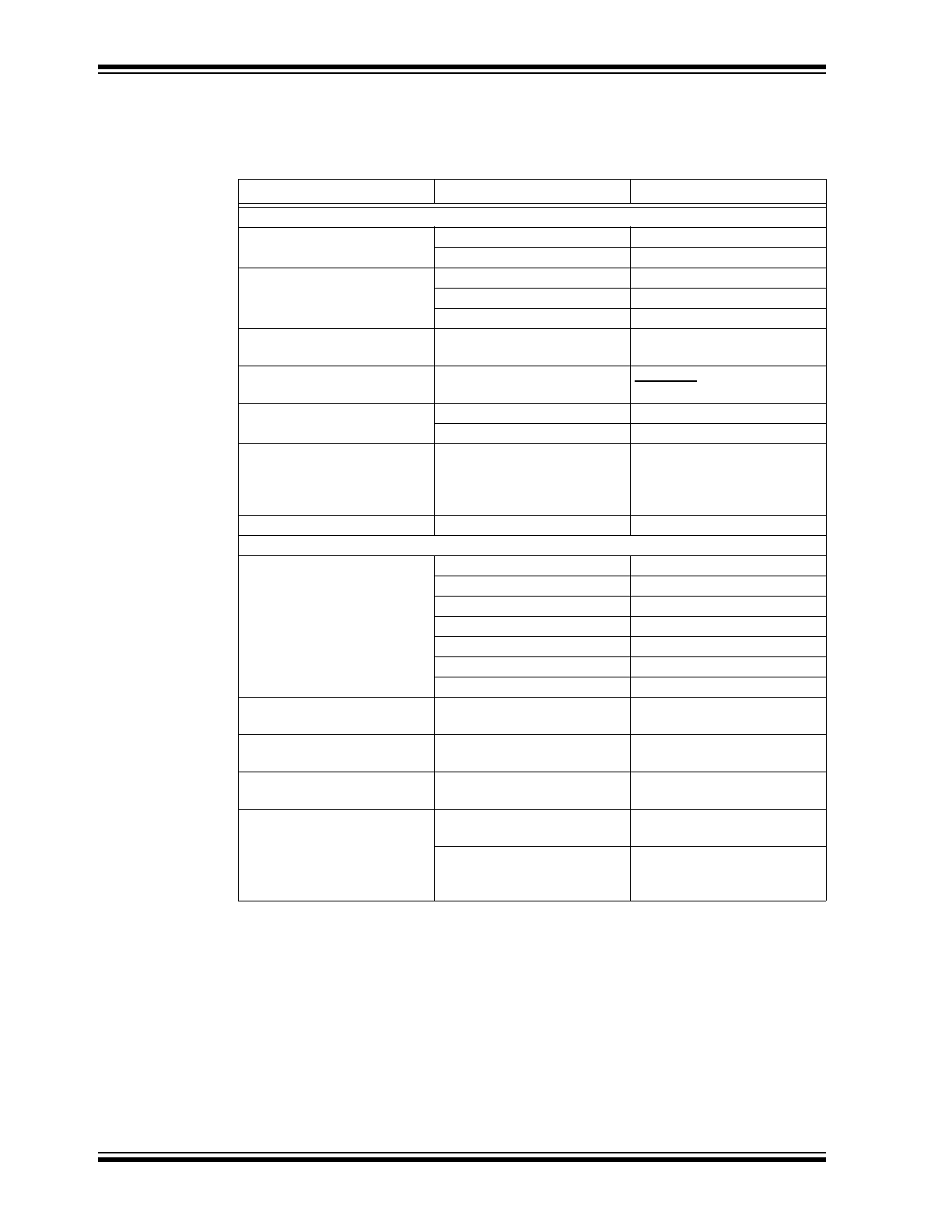
DOCUMENTATION CONVENTIONS
Description
Represents
Examples
Arial font:
Italic characters
Referenced books
MPLAB
®
IDE User’s Guide
Emphasized text
...is the only compiler...
Initial caps
A window
the Output window
A dialog
the Settings dialog
A menu selection
select Enable Programmer
Quotes
A field name in a window or
dialog
“Save project before build”
Underlined, italic text with
right angle bracket
A menu path
File>Save
Bold characters
A dialog button
Click OK
A tab
Click the Power tab
N‘Rnnnn
A number in verilog format,
where N is the total number of
digits, R is the radix and n is a
digit.
4‘b0010, 2‘hF1
Text in angle brackets < >
A key on the keyboard
Press <Enter>, <F1>
Courier New font:
Plain Courier New
Sample source code
#define START
Filenames
autoexec.bat
File paths
c:\mcc18\h
Keywords
_asm, _endasm, static
Command-line options
-Opa+, -Opa-
Bit values
0, 1
Constants
0xFF, ‘A’
Italic Courier New
A variable argument
file.o
, where file can be
any valid filename
Square brackets [ ]
Optional arguments
mcc18 [options] file
[options]
Curly brackets and pipe
character: { | }
Choice of mutually exclusive
arguments; an OR selection
errorlevel {0|1}
Ellipses...
Replaces repeated text
var_name [,
var_name...]
Represents code supplied by
user
void main (void)
{ ...
}

Preface
© 2011 Microchip Technology Inc.
DS51932B-page 7
RECOMMENDED READING
This user's guide describes how to use MCP47X6 PICtail™ Plus Daughter Board. The
following Microchip documents are available and recommended as supplemental
reference resources.
PICkit™ Serial Analyzer User’s Guide (DS51647)
Consult this document for instructions on how to use the PICkit™ Serial Analyzer
hardware and software.
MCP4706/MCP4716/MCP4726 Data Sheet, “8-/10-/12-Bit Voltage Output
Digital-to-Analog Converter with EEPROM Memory” (DS22272)
This data sheet provides detailed information regarding the MCP47x6 product family.
PIC24FJ128GA010 Family Data Sheet (DS39747)
Explorer 16 Development Board User’s Guide (DS51589)
AN1079, “Using the C30 Compiler and the I2C Peripheral to Interface Serial
EEPROMs with dsPIC33F” (DS01079)
THE MICROCHIP WEB SITE
Microchip provides online support via our web site at
www.microchip.com
. This web
site is used as a means to make files and information easily available to customers.
Accessible by using your favorite Internet browser, the web site contains the following
information:
• Product Support – Data sheets and errata, application notes and sample
programs, design resources, user’s guides and hardware support documents,
latest software releases and archived software
• General Technical Support – Frequently Asked Questions (FAQs), technical
support requests, online discussion groups, Microchip consultant program
member listing
• Business of Microchip – Product selector and ordering guides, latest Microchip
press releases, listing of seminars and events, listings of Microchip sales offices,
distributors and factory representatives
CUSTOMER SUPPORT
Users of Microchip products can receive assistance through several channels:
• Distributor or Representative
• Local Sales Office
• Field Application Engineer (FAE)
• Technical Support
Customers should contact their distributor, representative or field application engineer
(FAE) for support. Local sales offices are also available to help customers. A listing of
sales offices and locations is included in the back of this document.
Technical support is available through the web site at:
http://support.microchip.com
.

MCP47X6 PICtail™ Plus Daughter Board User’s Guide
DS51932B-page 8
© 2011 Microchip Technology Inc.
DOCUMENT REVISION HISTORY
Revision B (October 2011)
• Replaced the front and back views of the board with updated photos for
Figure
1-1: “Front and Back Views of the MCP47X6 PICtail™ Plus Daughter Board.”
• Added buzzer information to
Appendix B. “Bill Of Materials (BOM)”
.
Revision A (May 2011)
• Initial Release of this Document.
MCP47X6 PICtail™ PLUS DAUGHTER
BOARD USER’S GUIDE
© 2011 Microchip Technology Inc.
DS51932B-page 9
Chapter 1. Quick Start Instructions
1.1
INTRODUCTION
The following sections provide an overview of the MCP47X6 PICtail™ Plus Daughter
Board and demonstrate how to: (a) use these devices in a 16-bit MCU environment and
(b) evaluate these device’s features using the PICkit™ Serial Analyzer (P/N:
DV164122). The MCP47X6 PICtail™ Plus Daughter Board is designed to work with
both the Explorer 16 Development Board (P/N: DV164033) and the PICkit
™
Serial
Analyzer (P/N: DV164122).
The following topics are covered:
• Description of the MCP47X6 PICtail™ Plus Daughter Board.
• How to use the MCP47X6 PICtail™ Plus Daughter Board with the Explorer 16
Starter Kit.
• How to use MCP47X6 PICtail™ Plus Daughter Board with the PICkit
™
Serial
Analyzer.
1.2
DESCRIPTION OF THE MCP47X6 PICtail™ PLUS DAUGHTER BOARD
The MCP47X6 PICtail™ Plus Daughter Board (P/N ADM00317) contains the
MCP4706 (8-bit DAC), MCP4716 (10-bit DAC), and MCP4726 (12-bit DAC) devices.
These DAC devices are communicating with the external Master device (MCU) using
I
2
C serial interface communication. The MCP47X6 PICtail™ Plus Daughter Board
does not include the Master device (MCU), but it has two interface connectors that can
be used for the external device, which has the Master device (MCU) to communicate
with this board. The two interfaces are:
(a) Connector (J3) for Explorer 16 Starter Kit (P/N: DV164033) for 16-bit MCU
environment. The firmware for the 16-bit MCU is provided with this board.
(b) 6-pin connector (J1) for PICkit™ Serial Analyzer (P/N: DV164122) for reading and
writing the DAC registers using the PICkit™ Serial Analyzer PC software.
The user can connect the MCP47X6 PICtail™ Plus Daughter Board to one of the above
tools and perform their own experiments.
These two external devices are used to control the DAC devices on the daughter
board. The user can choose one of these tools to use along with the daughter board.
The MCP47X6 PICtail™ Plus Daughter Board has test points for SCL and SDA, and
V
OUT
pads for each device. By connecting an oscilloscope to these test points (to SCL,
SDA, V
OUT
) or a digital multimeter to the V
OUT
pads, the user can examine the data
communications through the I
2
C
™
bus line and observe the resulting DAC output
(V
OUT
). Refer to
Appendix A. “Schematic and Layouts”
.
Note 1:
If you use the PIC Explorer 16, you need Sections 1.4
—
1.5 only.
2:
If you use the PICkit
™
Serial Analyzer, you need Sections 1.6
—
1.8 only.
Note:
The user can also control the DAC devices on the MCP47X6 PICtail™ Plus
Daughter Board by providing I
2
C commands through the interface
communication terminals on the daughter board, without using the Explorer
16 Development Board or the PICkit
TM
Serial Analyzer.
MCP47X6 PICtail™ Plus Daughter Board User’s Guide
DS51932B-page 10
© 2011 Microchip Technology Inc.
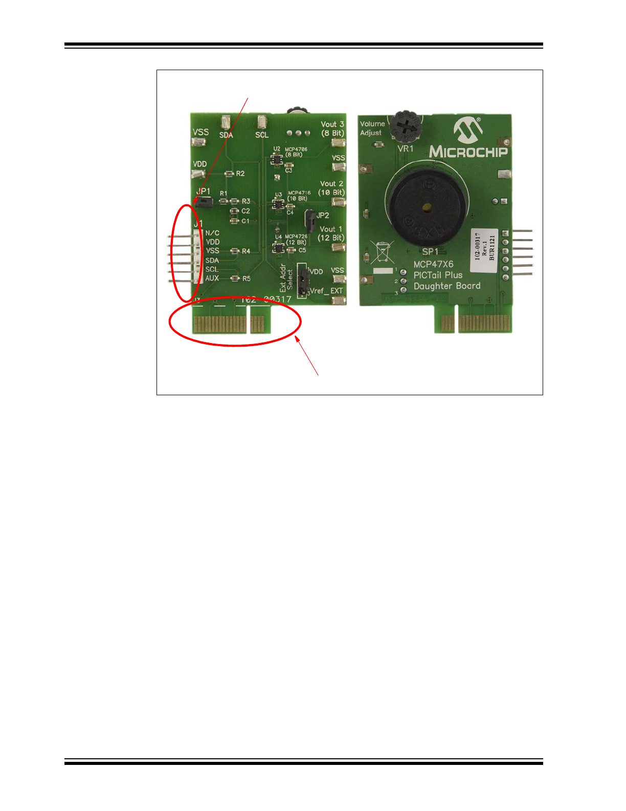
FIGURE 1-1:
Front and Back Views of the MCP47X6 PICtail™ Plus Daughter
Board.
Connector for Explorer 16 Development Board
Connector for PICkit
TM
Serial Analyzer
104-00317-R1
(a) Front View
(b) Back View