

2008-2016 Microchip Technology Inc.
DS00002308A-page 1
Highlights
• Up to 200Mbps via Turbo MII Interface
• High performance, full featured 3 port switch with
VLAN, QoS packet prioritization, Rate Limiting,
IGMP monitoring and management functions
• Serial management via I
2
C or SMI
• Unique Virtual PHY feature simplifies software
development by mimicking the multiple switch
ports as a single port PHY
Target Applications
• Cable, satellite, and IP set-top boxes
• Digital televisions
• Digital video recorders
• VoIP/Video phone systems
• Home gateways
• Test/Measurement equipment
• Industrial automation systems
Key Benefits
• Ethernet Switch Fabric
- 32K buffer RAM
- 512 entry forwarding table
- Port based IEEE 802.1Q VLAN support (16
groups)
–Programmable IEEE 802.1Q tag insertion/removal
- IEEE 802.1D spanning tree protocol support
- 4 separate transmit queues available per port
- Fixed or weighted egress priority servicing
- QoS/CoS Packet prioritization
–Input priority determined by VLAN tag, DA lookup,
TOS, DIFFSERV or port default value
–Programmable Traffic Class map based on input
priority on per port basis
–Remapping of 802.1Q priority field on per port basis
–Programmable rate limiting at the ingress with
coloring and random early discard, per port /
priority
–Programmable rate limiting at the egress with leaky
bucket algorithm, per port / priority
- IGMP v1/v2/v3 monitoring for Multicast
packet filtering
- Programmable broadcast storm protection
with global % control and enable per port
- Programmable buffer usage limits
- Dynamic queues on internal memory
- Programmable filter by MAC address
• Switch Management
- Port mirroring/monitoring/sniffing: ingress
and/or egress traffic on any port or port pair
- Fully compliant statistics (MIB) gathering
counters
- Control registers configurable on-the-fly
• Ports
- Port 0 - MII MAC, MII PHY, RMII PHY modes
- 2 internal 10/100 PHYs with HP Auto-MDIX
support
- 200Mbps Turbo MII (PHY or MAC mode)
- Fully compliant with IEEE 802.3 standards
- 10BASE-T and 100BASE-TX support
- Full and half duplex support
- Full duplex flow control
- Backpressure (forced collision) half duplex
flow control
- Automatic flow control based on programma-
ble levels
- Automatic 32-bit CRC generation & checking
- 2K Jumbo packet support
- Programmable interframe gap, flow control
pause value
- Full transmit/receive statistics
- Full LED support per port
- Auto-negotiation
- Automatic polarity correction
- Automatic MDI/MDI-X
- Loop-back mode
• Serial Management
- I
2
C (slave) access to all internal registers
- MIIM (MDIO) access to PHY related registers
- SMI (extended MIIM) access to all internal
registers
• Other Features
- General Purpose Timer
- I
2
C Serial EEPROM interface
- Programmable GPIOs/LEDs
• Single 3.3V power supply
• ESD Protection Levels
- ±8kV HBM without External Protection
Devices
- ±8kV contact mode (IEC61000-4-2)
- ±15kV air-gap discharge mode
(IEC61000-4-2)
• Latch-up exceeds ±150mA per EIA/JESD 78
• 56-pin QFN (8x8mm) RoHS Compliant Pkg.
• Available in Commercial & Industrial Temp.
Ranges
LAN9303/LAN9303i
Small Form Factor Three Port 10/100 Managed
Ethernet Switch with Single MII/RMII/Turbo MII

LAN9303/LAN9303i
DS00002308A-page 2
2008-2016 Microchip Technology Inc.
TO OUR VALUED CUSTOMERS
It is our intention to provide our valued customers with the best documentation possible to ensure successful use of your Microchip
products. To this end, we will continue to improve our publications to better suit your needs. Our publications will be refined and
enhanced as new volumes and updates are introduced.
If you have any questions or comments regarding this publication, please contact the Marketing Communications Department via
E-mail at
docerrors@microchip.com
. We welcome your feedback.
Most Current Data Sheet
To obtain the most up-to-date version of this data sheet, please register at our Worldwide Web site at:
http://www.microchip.com
You can determine the version of a data sheet by examining its literature number found on the bottom outside corner of any page.
The last character of the literature number is the version number, (e.g., DS30000000A is version A of document DS30000000).
Errata
An errata sheet, describing minor operational differences from the data sheet and recommended workarounds, may exist for cur-
rent devices. As device/documentation issues become known to us, we will publish an errata sheet. The errata will specify the
revision of silicon and revision of document to which it applies.
To determine if an errata sheet exists for a particular device, please check with one of the following:
• Microchip’s Worldwide Web site;
http://www.microchip.com
• Your local Microchip sales office (see last page)
When contacting a sales office, please specify which device, revision of silicon and data sheet (include -literature number) you are
using.
Customer Notification System
Register on our web site at
www.microchip.com
to receive the most current information on all of our products.

2008-2016 Microchip Technology Inc.
DS00002308A-page 3
LAN9303/LAN9303i
Table of Contents
1.0 Preface ............................................................................................................................................................................................ 4
2.0 Introduction ..................................................................................................................................................................................... 6
3.0 Pin Description and Configuration ................................................................................................................................................ 13
4.0 Clocking, Resets, and Power Management .................................................................................................................................. 30
5.0 System Interrupts .......................................................................................................................................................................... 41
6.0 Switch Fabric ................................................................................................................................................................................ 45
7.0 Ethernet PHYs .............................................................................................................................................................................. 70
8.0 Serial Management ....................................................................................................................................................................... 85
9.0 MII Data Interface ....................................................................................................................................................................... 100
10.0 MII Management ....................................................................................................................................................................... 103
11.0 General Purpose Timer & Free-Running Clock ........................................................................................................................ 110
12.0 GPIO/LED Controller ................................................................................................................................................................ 111
13.0 Register Descriptions ................................................................................................................................................................ 114
14.0 Operational Characteristics ....................................................................................................................................................... 239
15.0 Package Outlines ...................................................................................................................................................................... 258
Appendix A: Data sheet Revision History ......................................................................................................................................... 260
The Microchip Web Site .................................................................................................................................................................... 261
Customer Change Notification Service ............................................................................................................................................. 261
Customer Support ............................................................................................................................................................................. 261
Product Identification System ........................................................................................................................................................... 262

LAN9303/LAN9303i
DS00002308A-page 4
2008-2016 Microchip Technology Inc.
1.0
PREFACE
1.1
General Terms
10BASE-T
10BASE-T (10Mbps Ethernet, IEEE 802.3)
100BASE-TX
100BASE-TX (100Mbps Fast Ethernet, IEEE 802.3u)
ADC
Analog-to-Digital Converter
ALR
Address Logic Resolution
BLW
Baseline Wander
BM
Buffer Manager - Part of the switch fabric
BPDU
Bridge Protocol Data Unit - Messages which carry the Spanning Tree
Protocol information
Byte
8-bits
CSMA/CD
Carrier Sense Multiple Access / Collision Detect
CSR
Control and Status Registers
CTR
Counter
DA
Destination Address
DWORD
32-bits
EPC
EEPROM Controller
FCS
Frame Check Sequence - The extra checksum characters added to the end
of an Ethernet frame, used for error detection and correction.
FIFO
First In First Out buffer
FSM
Finite State Machine
GPIO
General Purpose I/O
Host
External system (Includes processor, application software, etc.)
IGMP
Internet Group Management Protocol
Inbound
Refers to data input to the device from the host
Level-Triggered Sticky Bit
This type of status bit is set whenever the condition that it represents is
asserted. The bit remains set until the condition is no longer true, and the
status bit is cleared by writing a zero.
lsb
Least Significant Bit
LSB
Least Significant Byte
MDI
Medium Dependant Interface
MDIX
Media Independent Interface with Crossover
MII
Media Independent Interface
MIIM
Media Independent Interface Management
MIL
MAC Interface Layer
MLT-3
Multi-Level Transmission Encoding (3-Levels). A tri-level encoding method
where a change in the logic level represents a code bit “1” and the logic
output remaining at the same level represents a code bit “0”.
msb
Most Significant Bit
MSB
Most Significant Byte
NRZI
Non Return to Zero Inverted. This encoding method inverts the signal for a
“1” and leaves the signal unchanged for a “0”
N/A
Not Applicable
NC
No Connect
OUI
Organizationally Unique Identifier
Outbound
Refers to data output from the device to the host
PISO
Parallel In Serial Out

2008-2016 Microchip Technology Inc.
DS00002308A-page 5
LAN9303/LAN9303i
PLL
Phase Locked Loop
PTP
Precision Time Protocol
RESERVED
Refers to a reserved bit field or address. Unless otherwise noted, reserved
bits must always be zero for write operations. Unless otherwise noted, values
are not ensured when reading reserved bits. Unless otherwise noted, do not
read or write to reserved addresses.
RTC
Real-Time Clock
SA
Source Address
SFD
Start of Frame Delimiter - The 8-bit value indicating the end of the preamble
of an Ethernet frame.
SIPO
Serial In Parallel Out
SMI
Serial Management Interface
SQE
Signal Quality Error (also known as “heartbeat”)
SSD
Start of Stream Delimiter
UDP
User Datagram Protocol - A connectionless protocol run on top of IP
networks
UUID
Universally Unique IDentifier
WORD
16-bits

LAN9303/LAN9303i
DS00002308A-page 6
2008-2016 Microchip Technology Inc.
2.0
INTRODUCTION
2.1
General Description
The LAN9303/LAN9303i is a full featured, 3 port 10/100 managed Ethernet switch designed for embedded applications
where performance, flexibility, ease of integration and system cost control are required. The LAN9303/LAN9303i com-
bines all the functions of a 10/100 switch system, including the Switch Fabric, packet buffers, Buffer Manager, Media
Access Controllers (MACs), PHY transceivers, and serial management. The LAN9303/LAN9303i complies with the
IEEE 802.3 (full/half-duplex 10BASE-T and 100BASE-TX) Ethernet protocol specification and 802.1D/802.1Q network
management protocol specifications, enabling compatibility with industry standard Ethernet and Fast Ethernet applica-
tions.
At the core of the device is the high performance, high efficiency 3 port Ethernet Switch Fabric. The Switch Fabric con-
tains a 3 port VLAN layer 2 Switch Engine that supports untagged, VLAN tagged, and priority tagged frames. The Switch
Fabric provides an extensive feature set which includes spanning tree protocol support, multicast packet filtering and
Quality of Service (QoS) packet prioritization by VLAN tag, destination address, port default value or DIFFSERV/TOS,
allowing for a range of prioritization implementations. 32K of buffer RAM allows for the storage of multiple packets while
forwarding operations are completed, and a 512 entry forwarding table provides ample room for MAC address forward-
ing tables. Each port is allocated a cluster of 4 dynamic QoS queues which allow each queue size to grow and shrink
with traffic, effectively utilizing all available memory. This memory is managed dynamically via the Buffer Manager block
within the Switch Fabric. All aspects of the Switch Fabric are managed via the Switch Fabric configuration and status
registers, which are indirectly accessible via the system control and status registers.
The LAN9303/LAN9303i provides 3 switched ports. Each port is fully compliant with the IEEE 802.3 standard and all
internal MACs and PHYs support full/half duplex 10BASE-T and 100BASE-TX operation. The LAN9303/LAN9303i pro-
vides 2 on-chip PHYs, 1 Virtual PHY and 3 MACs. The Virtual PHY and the third MAC are used to connect the Switch
Fabric to an external MAC or PHY. In MAC mode, the device can be connected to an external PHY via the MII/Turbo
MII interface. In PHY mode, the device can be connected to an external MAC via the MII/RMII/Turbo MII interface. All
ports support automatic or manual full duplex flow control or half duplex backpressure (forced collision) flow control. 2K
jumbo packet (2048 byte) support allows for oversized packet transfers, effectively increasing throughput while decreas-
ing CPU load. All MAC and PHY related settings are fully configurable via their respective registers within the device.
The integrated I
2
C and SMI slave controllers allow for full serial management of the device via the integrated I
2
C or MII
interface, respectively. The inclusion of these interfaces allows for greater flexibility in the incorporation of the device
into various designs. It is this flexibility which allows the device to operate in 2 different modes and under various man-
agement conditions. In both MAC and PHY modes, the device can be SMI managed or I
2
C managed. This flexibility in
management makes the LAN9303/LAN9303i a candidate for virtually all switch applications.
The LAN9303/LAN9303i contains an I
2
C master EEPROM controller for connection to an optional EEPROM. This
allows for the storage and retrieval of static data. The internal EEPROM Loader can be optionally configured to auto-
matically load stored configuration settings from the EEPROM into the device at reset. The I
2
C management slave and
master EEPROM controller share common pins.
In addition to the primary functionality described above, the LAN9303/LAN9303i provides additional features designed
for extended functionality. These include a configurable 16-bit General Purpose Timer (GPT), a 32-bit 25MHz free run-
ning counter, and 6-bit configurable GPIO/LED interface.
The LAN9303/LAN9303i’s performance, features and small size make it an ideal solution for many applications in the
consumer electronics and industrial automation markets. Targeted applications include: set top boxes (cable, satellite
and IP), digital televisions, digital video recorders, voice over IP and video phone systems, home gateways, and test
and measurement equipment.
2008
-2016 Microchip
Technology In
c.
D
S
00002308A-
p
age 7
LAN9303/LAN9303i
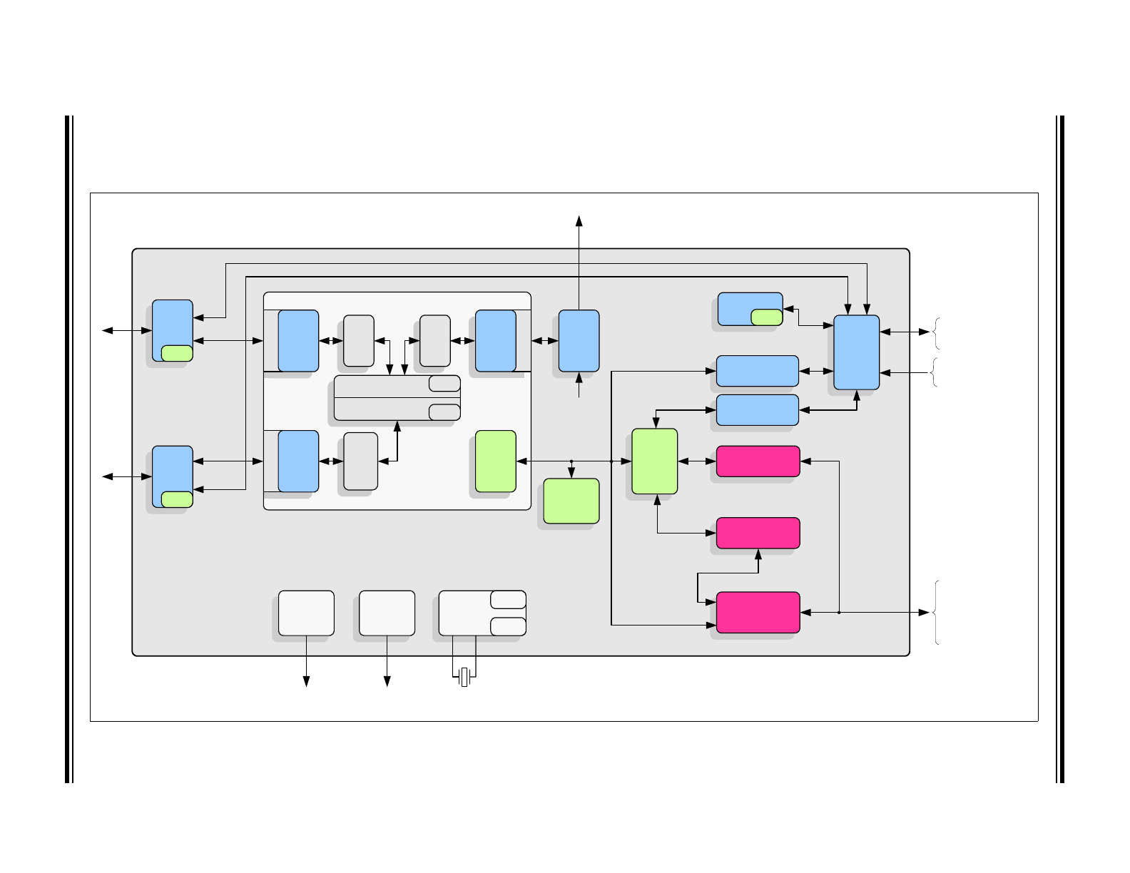
2.2
Block Diagram
FIGURE 2-1:
INTERNAL BLOCK DIAGRAM
To optional EEPROM
(via I
2
C master)
EEPROM Controller
I
2
C (master)
EEPROM Loader
Register
Access
MUX
SMI (slave)
Controller
System
Registers
(CSRs)
MII
Mode
MUX
MDIO
MDIO
To optional SMI Master
Mode Configuration
Straps
MDIO
PHY Management
Interface (PMI)
MDIO
Registers
Virtual PHY
10/100
PHY
Registers
10/100
PHY
Registers
Switch
Registers
(CSRs)
Switch Fabric
D
yna
m
ic
Qo
S
4 Queu
es
Dynam
ic
QoS
4 Que
u
es
D
yna
m
ic
Qo
S
4 Queu
es
Switch Engine
Buffer Manager
Search
Engine
Frame
Buffers
MII
MDIO
MDIO
Ethernet
Ethernet
LAN9303/
LAN9303i
GPIO/LED
Controller
To optional GPIOs/LEDs
System
Interrupt
Controller
IRQ
GP Timer
Free-Run
Clk
System
Clocks/
Reset/PME
Controller
External
25MHz Crystal
I
2
C
Por
t 0
10/100
MAC
Por
t 1
10/100
MAC
Por
t 2
10/100
MAC
MII
I
2
C Slave
Controller
Mode Configuration
Straps
MII
Data
Path
To optional CPU
serial management
(via I
2
C slave)
MII/Turbo MII to PHY or
MII/RMII/Turbo MII to MAC

LAN9303/LAN9303i
DS00002308A-page 8
2008-2016 Microchip Technology Inc.
2.2.1
SYSTEM CLOCKS/RESET/PME CONTROLLER
A clock module generates all the system clocks required by the device. This module interfaces directly with the external
25MHz crystal/oscillator to generate the required clock divisions for each internal module. A 16-bit general purpose timer
and 32-bit free-running clock are provided by this module for general purpose use. The Port 1 & 2 PHYs provide general
power-down and energy detect power-down modes, which allow a reduction in PHY power consumption.
The device reset events are categorized as chip-level resets, multi-module resets, and single-module resets. These
reset events are summarized below:
• Chip Level Resets
- Power-On Reset (Entire chip reset)
- nRST Pin Reset (Entire chip reset)
• Multi-Module Reset
- Digital Reset (All sub-modules except Ethernet PHYs)
• Single-Module Resets
- Port 2 PHY Reset
- Port 1 PHY Reset
- Virtual PHY Reset
2.2.2
SYSTEM INTERRUPT CONTROLLER
The device provides a multi-tier programmable interrupt structure which is controlled by the System Interrupt Controller.
Top level interrupt registers aggregate and control all interrupts from the various sub-modules. The device is capable of
generating interrupt events from the following:
• Switch Fabric
• Ethernet PHYs
• GPIOs
• General Purpose Timer
• Software (general purpose)
A dedicated programmable IRQ interrupt output pin is provided for external indication of any device interrupts. The IRQ
buffer type, polarity, and de-assertion interval are register configurable.
2.2.3
SWITCH FABRIC
The Switch Fabric consists of the following major function blocks:
• 10/100 MACs
There is one 10/100 Ethernet MAC per Switch Fabric port, which provides basic 10/100 Ethernet functionality,
including transmission deferral, collision back-off/retry, TX/RX FCS checking/generation, TX/RX pause flow con-
trol, and transmit back pressure. The 10/100 MACs act as an interface between the Switch Engine and the 10/100
PHYs (for ports 1 and 2). The port 0 10/100 MAC interfaces the Switch Engine to the external MAC/PHY (see
Sec-
tion 2.3, "Modes of Operation"
). Each 10/100 MAC includes RX and TX FIFOs and per port statistic counters.
• Switch Engine
This block, consisting of a 3 port VLAN layer 2 switching engine, provides the control for all forwarding/filtering
rules and supports untagged, VLAN tagged, and priority tagged frames. The Switch Engine provides an extensive
feature set which includes spanning tree protocol support, multicast packet filtering and Quality of Service (QoS)
packet prioritization by VLAN tag, destination address, and port default value or DIFFSERV/TOS, allowing for a
range of prioritization implementations. A 512 entry forwarding table provides ample room for MAC address for-
warding tables.
• Buffer Manager
This block controls the free buffer space, multi-level transmit queues, transmission scheduling, and packet drop-
ping of the Switch Fabric. 32K of buffer RAM allows for the storage of multiple packets while forwarding operations
are completed. Each port is allocated a cluster of 4 dynamic QoS queues which allow each queue size to grow
and shrink with traffic, effectively utilizing all available memory. This memory is managed dynamically via the Buf-
fer Manager block.
• Switch CSRs
This block contains all switch related control and status registers, and allows all aspects of the Switch Fabric to be
managed. These registers are indirectly accessible via the system control and status registers.

2008-2016 Microchip Technology Inc.
DS00002308A-page 9
LAN9303/LAN9303i
2.2.4
ETHERNET PHYS
The device contains three PHYs: Port 1 PHY, Port 2 PHY and a Virtual PHY. The Port 1 & 2 PHYs are identical in func-
tionality and each connect their corresponding Ethernet signal pins to the Switch Fabric MAC of their respective port.
These PHYs interface with their respective MAC via an internal MII interface. The Virtual PHY provides the virtual func-
tionality of a PHY and allows connection of an external MAC to port 0 of the Switch Fabric as if it was connected to a
single port PHY. All PHYs comply with the IEEE 802.3 Physical Layer for Twisted Pair Ethernet and can be configured
for full/half duplex 100 Mbps (100BASE-TX) or 10Mbps (10BASE-T) Ethernet operation. All PHY registers follow the
IEEE 802.3 (clause 22.2.4) specified MII management register set.
2.2.5
PHY MANAGEMENT INTERFACE (PMI)
The PHY Management Interface (PMI) is used to serially access the internal PHYs as well as the external PHY on the
MII pins (in MAC mode only, see
Section 2.3, "Modes of Operation"
). The PMI implements the IEEE 802.3 management
protocol, providing read/write commands for PHY configuration.
2.2.6
I
2
C SLAVE CONTROLLER
This module provides an I
2
C slave interface which can be used for CPU serial management of the device. The I
2
C slave
controller implements the low level I
2
C slave serial interface (start and stop condition detection, data bit transmis-
sion/reception, and acknowledge generation/reception), handles the slave command protocol, and performs system
register reads and writes. The I
2
C slave controller conforms to the NXP I
2
C-Bus Specification. A list of management
modes and configurations settings for these modes is discussed in
Section 2.3, "Modes of Operation"
2.2.7
SMI SLAVE CONTROLLER
This module provides a SMI slave interface which can be used for CPU management of the device via the MII pins, and
allows CPU access to all system CSRs. SMI uses the same pins and protocol of the IEEE MII management function,
and differs only in that SMI provides access to all internal registers by using a non-standard extended addressing map.
The SMI protocol co-exists with the MII management protocol by using the upper half of the PHY address space (16
through 31). A list of management modes and configurations settings for these modes is discussed in
Section 2.3,
"Modes of Operation"
.
2.2.8
EEPROM CONTROLLER/LOADER
The EEPROM Controller is an I
2
C master module which interfaces an optional external EEPROM with the system reg-
ister bus and the EEPROM Loader. Multiple sizes of external EEPROMs are supported along with various EEPROM
commands, allowing for the efficient storage and retrieval of static data. The I
2
C interface conforms to the NXP I
2
C-Bus
Specification.
The EEPROM Loader module interfaces to the EEPROM Controller, Ethernet PHYs, and the system CSRs. The
EEPROM Loader provides the automatic loading of configuration settings from the EEPROM into the device at reset,
allowing the device to operate unmanaged. The EEPROM Loader runs upon a pin reset (nRST), power-on reset (POR),
digital reset, or upon the issuance of a EEPROM RELOAD command.
2.2.9
GPIO/LED CONTROLLER
bit Six configurable general-purpose input/output pins are provided which are controlled via this module. These pins can
be individually configured via the GPIO/LED CSRs to function as inputs, push-pull outputs, or open drain outputs and
each is capable of interrupt generation with configurable polarity. The GPIO pins can be alternatively configured as LED
outputs to drive Ethernet status LEDs for external indication of various attributes of the switch ports.
2.3
Modes of Operation
The LAN9303/LAN9303i is designed to integrate into various embedded environments. To accomplish compatibility with
a wide range of applications, the LAN9303/LAN9303i ports can operate in the following modes:
• Port 0 - Independently configured for MII MAC, MII PHY, RMII PHY modes
• Port 1 - Internal PHY mode
• Port 2 - Internal PHY mode
The mode of the device is determined by the P0_MODE[2:0] (Port 0) pin straps.
LAN9303/LAN9303i
DS00002308A-page 10
2008-2016 Microchip Technology Inc.
The device can also be placed into the following management modes:
• SMI managed
• I
2
C managed
The management mode is determined by the MNGT1_LED4P and MNGT0_LED3P pin straps. These modes are
detailed in the following sections.
Figure 2-4
displays a typical system configuration for each Port 0 mode and manage-
ment type supported by the device. Refer to
Section 9.0, "MII Data Interface," on page 100
for additional information on
the usage of MII signals in each supported mode.
2.3.1
INTERNAL PHY MODE
Internal PHY mode (Port 1 and Port 2) utilizes the internal PHY for the network connection. The Switch Engine MAC’s
MII port is connected internally to the internal PHY in this mode. Internal PHY mode can operate at 10Mbps or 100Mbps.
When an EEPROM is connected, the EEPROM loader can be used to load the initial device configuration from the exter-
nal EEPROM via the I
2
C interface. Once operational, if managed, the CPU can use the I
2
C interface to read or write
the EEPROM.
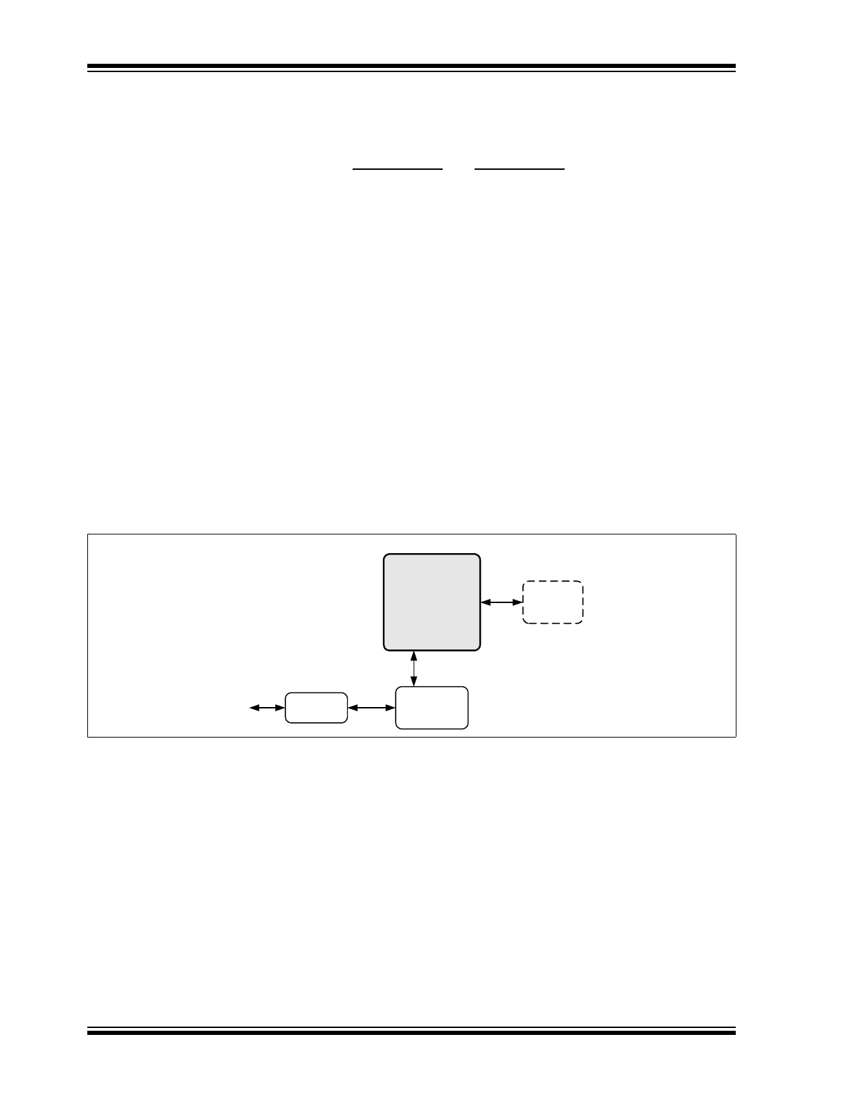
2.3.2
MAC MODE
MAC mode utilizes an external PHY, which is connected to the Port 0 MII pins, to provide an Ethernet network connec-
tion. In this mode, the port acts as a MAC, providing a communication path between the Switch Fabric and the external
PHY. MAC mode can operate at 10, 100, or 200Mbps (Turbo mode). In MAC mode, the device may be SMI managed
or I
2
C managed as detailed in
Section 2.3.4, "Management Modes"
.
When an EEPROM is connected, the EEPROM loader can be used to load the initial device configuration from the exter-
nal EEPROM via the I
2
C interface. Once operational, if managed, the CPU can use the I
2
C interface to read or write
the EEPROM.
2.3.3
PHY MODE
PHY mode utilizes an external MAC to provide a network path for the CPU. PHY mode supports MII and RMII interfaces.
The external MII/RMII pins must be connected to an external MAC, providing a communication path to the Switch Fabric.
MII PHY mode can operate at 10, 100, or 200Mbps (Turbo mode). RMII PHY mode can operate at 10 or 100Mbps. In
PHY mode, the device may be SMI managed or I
2
C managed as detailed in
Section 2.3.4, "Management Modes"
.
When an EEPROM is connected, the EEPROM loader can be used to load the initial device configuration from the exter-
nal EEPROM via the I
2
C interface. Once operational, if managed, the CPU can use the I
2
C interface to read or write
the EEPROM.
FIGURE 2-2:
MII MAC MODE
10/100
PHY
Ethernet
Magnetics
MII
MIIM/
SMI
EEPROM
(optional)
I
2
C EEPROM/
I
2
C slave
I
2
C
LAN9303/
LAN9303i
MII