

SMSC
LAN9210
DATASHEET
Revision 2.9 (03-01-12)
Datasheet
PRODUCT FEATURES
LAN9210
Small Form Factor Single-Chip
Ethernet Controller with HP Auto-MDIX
Support
Highlights
Optimized for standard performance applications
Efficient architecture with low CPU overhead
Easily interfaces to most 16-bit embedded CPU’s
Integrated PHY with HP Auto-MDIX support
Integrated checksum offload engine helps reduce
CPU load
Low pin count and small body size package for small
form factor system designs
Supports audio & video streaming over Ethernet:
multiple standard-definition (SD) MPEG2 streams
Target Applications
Basic cable, satellite, and IP set-top boxes
Digital video recorders
Video-over IP solutions, IP PBX & video phones
Wireless routers & access points
Audio distribution systems
Printers, kiosks, security systems
General embedded applications
Key Benefits
Non-PCI Ethernet controller for performance sensitive
applications
— 16-bit interface
— Burst-mode read support
Minimizes dropped packets
— Internal buffer memory can store over 200 packets
— Automatic PAUSE and back-pressure flow control
Minimizes CPU overhead
— Supports Slave-DMA
— Interrupt Pin with Programmable Hold-off timer
Reduces system cost and increases design flexibility
SRAM-like interface easily interfaces to most
embedded CPU’s or SoC’s
Reduced Power Modes
— Numerous power management modes
— Wake on LAN
— Magic packet wakeup
— Wakeup indicator event signal
— Link Status Change
Single chip Ethernet controller
— Fully compliant with IEEE 802.3/802.3u standards
— Integrated Ethernet MAC and PHY
— 10BASE-T and 100BASE-TX support
— Full- and Half-duplex support
— Full-duplex flow control
— Backpressure for half-duplex flow control
— Preamble generation and removal
— Automatic 32-bit CRC generation and checking
— Automatic payload padding and pad removal
— Loop-back modes
Flexible address filtering modes
— One 48-bit perfect address
— 64 hash-filtered multicast addresses
— Pass all multicast
— Promiscuous mode
— Inverse filtering
— Pass all incoming with status report
— Disable reception of broadcast packets
Integrated 10/100 Ethernet PHY
— Supports HP Auto-MDIX
— Auto-negotiation
— Supports energy-detect power down
Host bus interface
— Simple, SRAM-like interface
— 16-bit data bus
— 16Kbyte FIFO with flexible TX/RX allocation
— One configurable host interrupt
Miscellaneous features
— Small form factor, 56-pin QFN lead-free RoHS
Compliant package
— Integrated 1.8V regulator
— Integrated checksum offload engine
— Mixed endian support
— General Purpose Timer
— Optional EEPROM interface
— Support for 3 status LEDs multiplexed with
Programmable GPIO signals
Single 3.3V Power Supply with 5V tolerant I/O
0
°C to +70°C Commercial Temperature Support

Order Number(s):
LAN9210-ABZJ for 56-pin, QFN Lead-free RoHS Compliant package (0 to +70
°C Temp Range)
This product meets the halogen maximum concentration values per IEC61249-2-21
For RoHS compliance and environmental information, please visit
Small Form Factor Single-Chip Ethernet Controller with HP Auto-MDIX Support
Datasheet
Revision 2.9 (03-01-12)
2
SMSC
LAN9210
DATASHEET
Copyright © 2012 SMSC or its subsidiaries. All rights reserved.
Circuit diagrams and other information relating to SMSC products are included as a means of illustrating typical applications. Consequently, complete information sufficient for
construction purposes is not necessarily given. Although the information has been checked and is believed to be accurate, no responsibility is assumed for inaccuracies. SMSC
reserves the right to make changes to specifications and product descriptions at any time without notice. Contact your local SMSC sales office to obtain the latest specifications
before placing your product order. The provision of this information does not convey to the purchaser of the described semiconductor devices any licenses under any patent
rights or other intellectual property rights of SMSC or others. All sales are expressly conditional on your agreement to the terms and conditions of the most recently dated
version of SMSC's standard Terms of Sale Agreement dated before the date of your order (the "Terms of Sale Agreement"). The product may contain design defects or errors
known as anomalies which may cause the product's functions to deviate from published specifications. Anomaly sheets are available upon request. SMSC products are not
designed, intended, authorized or warranted for use in any life support or other application where product failure could cause or contribute to personal injury or severe property
damage. Any and all such uses without prior written approval of an Officer of SMSC and further testing and/or modification will be fully at the risk of the customer. Copies of
this document or other SMSC literature, as well as the Terms of Sale Agreement, may be obtained by visiting SMSC’s website at http://www.smsc.com. SMSC is a registered
trademark of Standard Microsystems Corporation (“SMSC”). Product names and company names are the trademarks of their respective holders.
SMSC DISCLAIMS AND EXCLUDES ANY AND ALL WARRANTIES, INCLUDING WITHOUT LIMITATION ANY AND ALL IMPLIED WARRANTIES OF MERCHANTABILITY,
FITNESS FOR A PARTICULAR PURPOSE, TITLE, AND AGAINST INFRINGEMENT AND THE LIKE, AND ANY AND ALL WARRANTIES ARISING FROM ANY COURSE
OF DEALING OR USAGE OF TRADE. IN NO EVENT SHALL SMSC BE LIABLE FOR ANY DIRECT, INCIDENTAL, INDIRECT, SPECIAL, PUNITIVE, OR CONSEQUENTIAL
DAMAGES; OR FOR LOST DATA, PROFITS, SAVINGS OR REVENUES OF ANY KIND; REGARDLESS OF THE FORM OF ACTION, WHETHER BASED ON CONTRACT;
TORT; NEGLIGENCE OF SMSC OR OTHERS; STRICT LIABILITY; BREACH OF WARRANTY; OR OTHERWISE; WHETHER OR NOT ANY REMEDY OF BUYER IS HELD
TO HAVE FAILED OF ITS ESSENTIAL PURPOSE, AND WHETHER OR NOT SMSC HAS BEEN ADVISED OF THE POSSIBILITY OF SUCH DAMAGES.

Small Form Factor Single-Chip Ethernet Controller with HP Auto-MDIX Support
Datasheet
SMSC
LAN9210
3
Revision 2.9 (03-01-12)
DATASHEET
Table of Contents
Chapter 1 General Description . . . . . . . . . . . . . . . . . . . . . . . . . . . . . . . . . . . . . . . . . . . . . . . . 9
1.1
Block Diagram . . . . . . . . . . . . . . . . . . . . . . . . . . . . . . . . . . . . . . . . . . . . . . . . . . . . . . . . . . . . . . . . 10
1.2
Internal Block Overview . . . . . . . . . . . . . . . . . . . . . . . . . . . . . . . . . . . . . . . . . . . . . . . . . . . . . . . . . 11
1.3
10/100 Ethernet PHY . . . . . . . . . . . . . . . . . . . . . . . . . . . . . . . . . . . . . . . . . . . . . . . . . . . . . . . . . . . 11
1.4
10/100 Ethernet MAC . . . . . . . . . . . . . . . . . . . . . . . . . . . . . . . . . . . . . . . . . . . . . . . . . . . . . . . . . . . 11
1.5
Receive and Transmit FIFOs . . . . . . . . . . . . . . . . . . . . . . . . . . . . . . . . . . . . . . . . . . . . . . . . . . . . . 12
1.6
Interrupt Controller . . . . . . . . . . . . . . . . . . . . . . . . . . . . . . . . . . . . . . . . . . . . . . . . . . . . . . . . . . . . . 12
1.7
GPIO Interface . . . . . . . . . . . . . . . . . . . . . . . . . . . . . . . . . . . . . . . . . . . . . . . . . . . . . . . . . . . . . . . . 12
1.8
Serial EEPROM Interface . . . . . . . . . . . . . . . . . . . . . . . . . . . . . . . . . . . . . . . . . . . . . . . . . . . . . . . . 12
1.9
Power Management Controls . . . . . . . . . . . . . . . . . . . . . . . . . . . . . . . . . . . . . . . . . . . . . . . . . . . . . 12
1.10 General Purpose Timer . . . . . . . . . . . . . . . . . . . . . . . . . . . . . . . . . . . . . . . . . . . . . . . . . . . . . . . . . 12
1.11 Host Bus Interface (SRAM Interface) . . . . . . . . . . . . . . . . . . . . . . . . . . . . . . . . . . . . . . . . . . . . . . . 13
Chapter 2 Pin Description and Configuration . . . . . . . . . . . . . . . . . . . . . . . . . . . . . . . . . . . 14
2.1
Pin List . . . . . . . . . . . . . . . . . . . . . . . . . . . . . . . . . . . . . . . . . . . . . . . . . . . . . . . . . . . . . . . . . . . . . . 15
2.2
Buffer Types . . . . . . . . . . . . . . . . . . . . . . . . . . . . . . . . . . . . . . . . . . . . . . . . . . . . . . . . . . . . . . . . . . 19
Chapter 3 Functional Description . . . . . . . . . . . . . . . . . . . . . . . . . . . . . . . . . . . . . . . . . . . . . 21
3.1
10/100 Ethernet MAC . . . . . . . . . . . . . . . . . . . . . . . . . . . . . . . . . . . . . . . . . . . . . . . . . . . . . . . . . . . 21
3.2
Flow Control . . . . . . . . . . . . . . . . . . . . . . . . . . . . . . . . . . . . . . . . . . . . . . . . . . . . . . . . . . . . . . . . . . 22
3.2.1
Full-Duplex Flow Control . . . . . . . . . . . . . . . . . . . . . . . . . . . . . . . . . . . . . . . . . . . . . . . . . 22
3.2.2
Half-Duplex Flow Control (Backpressure) . . . . . . . . . . . . . . . . . . . . . . . . . . . . . . . . . . . . 22
3.2.3
Virtual Local Area Network (VLAN) Support . . . . . . . . . . . . . . . . . . . . . . . . . . . . . . . . . . 22
3.3
Address Filtering Functional Description . . . . . . . . . . . . . . . . . . . . . . . . . . . . . . . . . . . . . . . . . . . . 23
3.4
Filtering Modes . . . . . . . . . . . . . . . . . . . . . . . . . . . . . . . . . . . . . . . . . . . . . . . . . . . . . . . . . . . . . . . . 24
3.4.1
Perfect Filtering . . . . . . . . . . . . . . . . . . . . . . . . . . . . . . . . . . . . . . . . . . . . . . . . . . . . . . . . 24
3.4.2
Hash Only Filtering . . . . . . . . . . . . . . . . . . . . . . . . . . . . . . . . . . . . . . . . . . . . . . . . . . . . . 24
3.5
Wake-up Frame Detection . . . . . . . . . . . . . . . . . . . . . . . . . . . . . . . . . . . . . . . . . . . . . . . . . . . . . . . 25
3.5.1
Magic Packet Detection . . . . . . . . . . . . . . . . . . . . . . . . . . . . . . . . . . . . . . . . . . . . . . . . . . 27
3.6
Checksum Offload Engines (COE) . . . . . . . . . . . . . . . . . . . . . . . . . . . . . . . . . . . . . . . . . . . . . . . . . 28
3.6.1
Receive Checksum Offload Engine (RXCOE). . . . . . . . . . . . . . . . . . . . . . . . . . . . . . . . . 28
3.6.2
Transmit Checksum Offload Engine (TXCOE) . . . . . . . . . . . . . . . . . . . . . . . . . . . . . . . . 31
3.7
Host Bus Operations. . . . . . . . . . . . . . . . . . . . . . . . . . . . . . . . . . . . . . . . . . . . . . . . . . . . . . . . . . . . 32
3.7.1
Bus Writes . . . . . . . . . . . . . . . . . . . . . . . . . . . . . . . . . . . . . . . . . . . . . . . . . . . . . . . . . . . . 32
3.7.2
Bus Reads . . . . . . . . . . . . . . . . . . . . . . . . . . . . . . . . . . . . . . . . . . . . . . . . . . . . . . . . . . . . 33
3.7.3
Mixed Endian Support . . . . . . . . . . . . . . . . . . . . . . . . . . . . . . . . . . . . . . . . . . . . . . . . . . . 33
3.7.4
Word Swap Function . . . . . . . . . . . . . . . . . . . . . . . . . . . . . . . . . . . . . . . . . . . . . . . . . . . . 33
3.8
General Purpose Timer (GP Timer) . . . . . . . . . . . . . . . . . . . . . . . . . . . . . . . . . . . . . . . . . . . . . . . . 36
3.9
EEPROM Interface . . . . . . . . . . . . . . . . . . . . . . . . . . . . . . . . . . . . . . . . . . . . . . . . . . . . . . . . . . . . . 37
3.9.1
MAC Address Auto-Load. . . . . . . . . . . . . . . . . . . . . . . . . . . . . . . . . . . . . . . . . . . . . . . . . 37
3.9.2
EEPROM Host Operations . . . . . . . . . . . . . . . . . . . . . . . . . . . . . . . . . . . . . . . . . . . . . . . 37
3.10 Power Management . . . . . . . . . . . . . . . . . . . . . . . . . . . . . . . . . . . . . . . . . . . . . . . . . . . . . . . . . . . . 42
3.10.1
System Description . . . . . . . . . . . . . . . . . . . . . . . . . . . . . . . . . . . . . . . . . . . . . . . . . . . . . 42
3.10.2
Functional Description . . . . . . . . . . . . . . . . . . . . . . . . . . . . . . . . . . . . . . . . . . . . . . . . . . . 42
3.10.3
Internal PHY Power-Down Modes . . . . . . . . . . . . . . . . . . . . . . . . . . . . . . . . . . . . . . . . . . 45
3.11 Detailed Reset Description . . . . . . . . . . . . . . . . . . . . . . . . . . . . . . . . . . . . . . . . . . . . . . . . . . . . . . . 46
3.11.1
Hardware Reset Input (nRESET) . . . . . . . . . . . . . . . . . . . . . . . . . . . . . . . . . . . . . . . . . . 47
3.11.2
Resume Reset Timing . . . . . . . . . . . . . . . . . . . . . . . . . . . . . . . . . . . . . . . . . . . . . . . . . . . 47
3.11.3
Soft Reset (SRST). . . . . . . . . . . . . . . . . . . . . . . . . . . . . . . . . . . . . . . . . . . . . . . . . . . . . . 47
3.11.4
PHY Reset Timing . . . . . . . . . . . . . . . . . . . . . . . . . . . . . . . . . . . . . . . . . . . . . . . . . . . . . . 47
3.12 TX Data Path Operation . . . . . . . . . . . . . . . . . . . . . . . . . . . . . . . . . . . . . . . . . . . . . . . . . . . . . . . . 47

Small Form Factor Single-Chip Ethernet Controller with HP Auto-MDIX Support
Datasheet
Revision 2.9 (03-01-12)
4
SMSC
LAN9210
DATASHEET
3.12.1
TX Buffer Format . . . . . . . . . . . . . . . . . . . . . . . . . . . . . . . . . . . . . . . . . . . . . . . . . . . . . . . 49
3.12.2
TX Command Format . . . . . . . . . . . . . . . . . . . . . . . . . . . . . . . . . . . . . . . . . . . . . . . . . . . 50
3.12.3
TX Data Format . . . . . . . . . . . . . . . . . . . . . . . . . . . . . . . . . . . . . . . . . . . . . . . . . . . . . . . . 52
3.12.4
TX Status Format . . . . . . . . . . . . . . . . . . . . . . . . . . . . . . . . . . . . . . . . . . . . . . . . . . . . . . 53
3.12.5
Calculating Actual TX Data FIFO Usage . . . . . . . . . . . . . . . . . . . . . . . . . . . . . . . . . . . . . 54
3.12.6
Transmit Examples . . . . . . . . . . . . . . . . . . . . . . . . . . . . . . . . . . . . . . . . . . . . . . . . . . . . . 55
3.12.7
Transmitter Errors . . . . . . . . . . . . . . . . . . . . . . . . . . . . . . . . . . . . . . . . . . . . . . . . . . . . . . 60
3.12.8
Stopping and Starting the Transmitter. . . . . . . . . . . . . . . . . . . . . . . . . . . . . . . . . . . . . . . 60
3.13 RX Data Path Operation . . . . . . . . . . . . . . . . . . . . . . . . . . . . . . . . . . . . . . . . . . . . . . . . . . . . . . . . . 60
3.13.1
RX Slave PIO Operation . . . . . . . . . . . . . . . . . . . . . . . . . . . . . . . . . . . . . . . . . . . . . . . . . 61
3.13.2
RX Packet Format . . . . . . . . . . . . . . . . . . . . . . . . . . . . . . . . . . . . . . . . . . . . . . . . . . . . . . 63
3.13.3
RX Status Format . . . . . . . . . . . . . . . . . . . . . . . . . . . . . . . . . . . . . . . . . . . . . . . . . . . . . . 64
3.13.4
Stopping and Starting the Receiver. . . . . . . . . . . . . . . . . . . . . . . . . . . . . . . . . . . . . . . . . 65
3.13.5
Receiver Errors . . . . . . . . . . . . . . . . . . . . . . . . . . . . . . . . . . . . . . . . . . . . . . . . . . . . . . . . 65
Chapter 4 Internal Ethernet PHY . . . . . . . . . . . . . . . . . . . . . . . . . . . . . . . . . . . . . . . . . . . . . 66
4.1
Top Level Functional Description . . . . . . . . . . . . . . . . . . . . . . . . . . . . . . . . . . . . . . . . . . . . . . . . . . 66
4.2
100Base-TX Transmit. . . . . . . . . . . . . . . . . . . . . . . . . . . . . . . . . . . . . . . . . . . . . . . . . . . . . . . . . . . 66
4.2.1
4B/5B Encoding. . . . . . . . . . . . . . . . . . . . . . . . . . . . . . . . . . . . . . . . . . . . . . . . . . . . . . . . 66
4.2.2
Scrambling. . . . . . . . . . . . . . . . . . . . . . . . . . . . . . . . . . . . . . . . . . . . . . . . . . . . . . . . . . . . 68
4.2.3
NRZI and MLT3 Encoding . . . . . . . . . . . . . . . . . . . . . . . . . . . . . . . . . . . . . . . . . . . . . . . . 68
4.2.4
100M Transmit Driver . . . . . . . . . . . . . . . . . . . . . . . . . . . . . . . . . . . . . . . . . . . . . . . . . . . 68
4.2.5
100M Phase Lock Loop (PLL) . . . . . . . . . . . . . . . . . . . . . . . . . . . . . . . . . . . . . . . . . . . . . 68
4.3
100Base-TX Receive . . . . . . . . . . . . . . . . . . . . . . . . . . . . . . . . . . . . . . . . . . . . . . . . . . . . . . . . . . . 69
4.3.1
100M Receive Input. . . . . . . . . . . . . . . . . . . . . . . . . . . . . . . . . . . . . . . . . . . . . . . . . . . . . 69
4.3.2
Equalizer, Baseline Wander Correction and Clock and Data Recovery . . . . . . . . . . . . . 69
4.3.3
NRZI and MLT-3 Decoding . . . . . . . . . . . . . . . . . . . . . . . . . . . . . . . . . . . . . . . . . . . . . . . 69
4.3.4
Descrambling. . . . . . . . . . . . . . . . . . . . . . . . . . . . . . . . . . . . . . . . . . . . . . . . . . . . . . . . . . 70
4.3.5
Alignment. . . . . . . . . . . . . . . . . . . . . . . . . . . . . . . . . . . . . . . . . . . . . . . . . . . . . . . . . . . . . 70
4.3.6
5B/4B Decoding. . . . . . . . . . . . . . . . . . . . . . . . . . . . . . . . . . . . . . . . . . . . . . . . . . . . . . . . 70
4.4
10Base-T Transmit . . . . . . . . . . . . . . . . . . . . . . . . . . . . . . . . . . . . . . . . . . . . . . . . . . . . . . . . . . . . . 70
4.4.1
10M Transmit Data across the internal MII bus . . . . . . . . . . . . . . . . . . . . . . . . . . . . . . . . 70
4.4.2
Manchester Encoding . . . . . . . . . . . . . . . . . . . . . . . . . . . . . . . . . . . . . . . . . . . . . . . . . . . 70
4.4.3
10M Transmit Drivers . . . . . . . . . . . . . . . . . . . . . . . . . . . . . . . . . . . . . . . . . . . . . . . . . . . 71
4.5
10Base-T Receive . . . . . . . . . . . . . . . . . . . . . . . . . . . . . . . . . . . . . . . . . . . . . . . . . . . . . . . . . . . . . 71
4.5.1
10M Receive Input and Squelch . . . . . . . . . . . . . . . . . . . . . . . . . . . . . . . . . . . . . . . . . . . 71
4.5.2
Manchester Decoding . . . . . . . . . . . . . . . . . . . . . . . . . . . . . . . . . . . . . . . . . . . . . . . . . . . 71
4.5.3
Jabber Detection . . . . . . . . . . . . . . . . . . . . . . . . . . . . . . . . . . . . . . . . . . . . . . . . . . . . . . . 71
4.6
Auto-negotiation . . . . . . . . . . . . . . . . . . . . . . . . . . . . . . . . . . . . . . . . . . . . . . . . . . . . . . . . . . . . . . . 71
4.7
Parallel Detection . . . . . . . . . . . . . . . . . . . . . . . . . . . . . . . . . . . . . . . . . . . . . . . . . . . . . . . . . . . . . . 73
4.7.1
Re-starting Auto-negotiation . . . . . . . . . . . . . . . . . . . . . . . . . . . . . . . . . . . . . . . . . . . . . . 73
4.7.2
Disabling Auto-negotiation. . . . . . . . . . . . . . . . . . . . . . . . . . . . . . . . . . . . . . . . . . . . . . . . 73
4.7.3
Half vs. Full-Duplex . . . . . . . . . . . . . . . . . . . . . . . . . . . . . . . . . . . . . . . . . . . . . . . . . . . . . 73
4.8
HP Auto-MDIX . . . . . . . . . . . . . . . . . . . . . . . . . . . . . . . . . . . . . . . . . . . . . . . . . . . . . . . . . . . . . . . . 74
Chapter 5 Register Description . . . . . . . . . . . . . . . . . . . . . . . . . . . . . . . . . . . . . . . . . . . . . . . 76
5.1
Register Nomenclature and Access Attributes . . . . . . . . . . . . . . . . . . . . . . . . . . . . . . . . . . . . . . . . 77
5.2
RX and TX FIFO Ports . . . . . . . . . . . . . . . . . . . . . . . . . . . . . . . . . . . . . . . . . . . . . . . . . . . . . . . . . . 77
5.2.1
RX FIFO Ports . . . . . . . . . . . . . . . . . . . . . . . . . . . . . . . . . . . . . . . . . . . . . . . . . . . . . . . . . 77
5.2.2
TX FIFO Ports . . . . . . . . . . . . . . . . . . . . . . . . . . . . . . . . . . . . . . . . . . . . . . . . . . . . . . . . . 77
5.3
System Control and Status Registers. . . . . . . . . . . . . . . . . . . . . . . . . . . . . . . . . . . . . . . . . . . . . . . 78
5.3.1
ID_REV—Chip ID and Revision . . . . . . . . . . . . . . . . . . . . . . . . . . . . . . . . . . . . . . . . . . . 79
5.3.2
IRQ_CFG—Interrupt Configuration Register . . . . . . . . . . . . . . . . . . . . . . . . . . . . . . . . . . 79
5.3.3
INT_STS—Interrupt Status Register . . . . . . . . . . . . . . . . . . . . . . . . . . . . . . . . . . . . . . . . 81

Small Form Factor Single-Chip Ethernet Controller with HP Auto-MDIX Support
Datasheet
SMSC
LAN9210
5
Revision 2.9 (03-01-12)
DATASHEET
5.3.4
INT_EN—Interrupt Enable Register . . . . . . . . . . . . . . . . . . . . . . . . . . . . . . . . . . . . . . . . 83
5.3.5
BYTE_TEST—Byte Order Test Register. . . . . . . . . . . . . . . . . . . . . . . . . . . . . . . . . . . . . 84
5.3.6
FIFO_INT—FIFO Level Interrupts . . . . . . . . . . . . . . . . . . . . . . . . . . . . . . . . . . . . . . . . . . 84
5.3.7
RX_CFG—Receive Configuration Register. . . . . . . . . . . . . . . . . . . . . . . . . . . . . . . . . . . 85
5.3.8
TX_CFG—Transmit Configuration Register . . . . . . . . . . . . . . . . . . . . . . . . . . . . . . . . . . 86
5.3.9
HW_CFG—Hardware Configuration Register . . . . . . . . . . . . . . . . . . . . . . . . . . . . . . . . . 87
5.3.10
RX_DP_CTRL—Receive Datapath Control Register . . . . . . . . . . . . . . . . . . . . . . . . . . . 90
5.3.11
RX_FIFO_INF—Receive FIFO Information Register. . . . . . . . . . . . . . . . . . . . . . . . . . . . 91
5.3.12
TX_FIFO_INF—Transmit FIFO Information Register . . . . . . . . . . . . . . . . . . . . . . . . . . . 91
5.3.13
PMT_CTRL— Power Management Control Register . . . . . . . . . . . . . . . . . . . . . . . . . . . 92
5.3.14
GPIO_CFG—General Purpose IO Configuration Register . . . . . . . . . . . . . . . . . . . . . . . 94
5.3.15
GPT_CFG-General Purpose Timer Configuration Register . . . . . . . . . . . . . . . . . . . . . . 95
5.3.16
GPT_CNT-General Purpose Timer Current Count Register . . . . . . . . . . . . . . . . . . . . . . 96
5.3.17
WORD_SWAP—Word Swap Control . . . . . . . . . . . . . . . . . . . . . . . . . . . . . . . . . . . . . . . 96
5.3.18
FREE_RUN—Free-Run 25MHz Counter . . . . . . . . . . . . . . . . . . . . . . . . . . . . . . . . . . . . 97
5.3.19
RX_DROP– Receiver Dropped Frames Counter . . . . . . . . . . . . . . . . . . . . . . . . . . . . . . 97
5.3.20
MAC_CSR_CMD – MAC CSR Synchronizer Command Register . . . . . . . . . . . . . . . . . 98
5.3.21
MAC_CSR_DATA – MAC CSR Synchronizer Data Register . . . . . . . . . . . . . . . . . . . . . 98
5.3.22
AFC_CFG – Automatic Flow Control Configuration Register . . . . . . . . . . . . . . . . . . . . . 99
5.3.23
E2P_CMD – EEPROM Command Register . . . . . . . . . . . . . . . . . . . . . . . . . . . . . . . . . 101
5.3.24
E2P_DATA – EEPROM Data Register . . . . . . . . . . . . . . . . . . . . . . . . . . . . . . . . . . . . . 103
5.4
MAC Control and Status Registers. . . . . . . . . . . . . . . . . . . . . . . . . . . . . . . . . . . . . . . . . . . . . . . . 104
5.4.1
MAC_CR—MAC Control Register . . . . . . . . . . . . . . . . . . . . . . . . . . . . . . . . . . . . . . . . . 105
5.4.2
ADDRH—MAC Address High Register . . . . . . . . . . . . . . . . . . . . . . . . . . . . . . . . . . . . . 108
5.4.3
ADDRL—MAC Address Low Register. . . . . . . . . . . . . . . . . . . . . . . . . . . . . . . . . . . . . . 109
5.4.4
HASHH—Multicast Hash Table High Register . . . . . . . . . . . . . . . . . . . . . . . . . . . . . . . 110
5.4.5
HASHL—Multicast Hash Table Low Register . . . . . . . . . . . . . . . . . . . . . . . . . . . . . . . . 110
5.4.6
MII_ACC—MII Access Register. . . . . . . . . . . . . . . . . . . . . . . . . . . . . . . . . . . . . . . . . . . 111
5.4.7
MII_DATA—MII Data Register. . . . . . . . . . . . . . . . . . . . . . . . . . . . . . . . . . . . . . . . . . . . 111
5.4.8
FLOW—Flow Control Register . . . . . . . . . . . . . . . . . . . . . . . . . . . . . . . . . . . . . . . . . . . 112
5.4.9
VLAN1—VLAN1 Tag Register. . . . . . . . . . . . . . . . . . . . . . . . . . . . . . . . . . . . . . . . . . . . 113
5.4.10
VLAN2—VLAN2 Tag Register. . . . . . . . . . . . . . . . . . . . . . . . . . . . . . . . . . . . . . . . . . . . 113
5.4.11
WUFF—Wake-up Frame Filter . . . . . . . . . . . . . . . . . . . . . . . . . . . . . . . . . . . . . . . . . . . 114
5.4.12
WUCSR—Wake-up Control and Status Register . . . . . . . . . . . . . . . . . . . . . . . . . . . . . 114
5.4.13
COE_CR—Checksum Offload Engine Control Register . . . . . . . . . . . . . . . . . . . . . . . . 115
5.5
PHY Registers . . . . . . . . . . . . . . . . . . . . . . . . . . . . . . . . . . . . . . . . . . . . . . . . . . . . . . . . . . . . . . . 116
5.5.1
Basic Control Register . . . . . . . . . . . . . . . . . . . . . . . . . . . . . . . . . . . . . . . . . . . . . . . . . . 117
5.5.2
Basic Status Register . . . . . . . . . . . . . . . . . . . . . . . . . . . . . . . . . . . . . . . . . . . . . . . . . . 118
5.5.3
PHY Identifier 1 . . . . . . . . . . . . . . . . . . . . . . . . . . . . . . . . . . . . . . . . . . . . . . . . . . . . . . . 118
5.5.4
PHY Identifier 2 . . . . . . . . . . . . . . . . . . . . . . . . . . . . . . . . . . . . . . . . . . . . . . . . . . . . . . . 119
5.5.5
Auto-negotiation Advertisement . . . . . . . . . . . . . . . . . . . . . . . . . . . . . . . . . . . . . . . . . . 119
5.5.6
Auto-negotiation Link Partner Ability . . . . . . . . . . . . . . . . . . . . . . . . . . . . . . . . . . . . . . . 120
5.5.7
Auto-negotiation Expansion. . . . . . . . . . . . . . . . . . . . . . . . . . . . . . . . . . . . . . . . . . . . . . 121
5.5.8
Mode Control/Status . . . . . . . . . . . . . . . . . . . . . . . . . . . . . . . . . . . . . . . . . . . . . . . . . . . 121
5.5.9
Special Modes . . . . . . . . . . . . . . . . . . . . . . . . . . . . . . . . . . . . . . . . . . . . . . . . . . . . . . . . 122
5.5.10
Special Control/Status Indications . . . . . . . . . . . . . . . . . . . . . . . . . . . . . . . . . . . . . . . . . 123
5.5.11
Interrupt Source Flag. . . . . . . . . . . . . . . . . . . . . . . . . . . . . . . . . . . . . . . . . . . . . . . . . . . 124
5.5.12
Interrupt Mask . . . . . . . . . . . . . . . . . . . . . . . . . . . . . . . . . . . . . . . . . . . . . . . . . . . . . . . . 124
5.5.13
PHY Special Control/Status. . . . . . . . . . . . . . . . . . . . . . . . . . . . . . . . . . . . . . . . . . . . . . 125
Chapter 6 Timing Diagrams . . . . . . . . . . . . . . . . . . . . . . . . . . . . . . . . . . . . . . . . . . . . . . . . . 126
6.1
Host Interface Timing . . . . . . . . . . . . . . . . . . . . . . . . . . . . . . . . . . . . . . . . . . . . . . . . . . . . . . . . . . 126
6.1.1
Special Restrictions on Back-to-Back Write/Read Cycles . . . . . . . . . . . . . . . . . . . . . . . 126
6.1.2
Special Restrictions on Back-to-Back Read Cycles . . . . . . . . . . . . . . . . . . . . . . . . . . . 128

Small Form Factor Single-Chip Ethernet Controller with HP Auto-MDIX Support
Datasheet
Revision 2.9 (03-01-12)
6
SMSC
LAN9210
DATASHEET
6.2
PIO Reads . . . . . . . . . . . . . . . . . . . . . . . . . . . . . . . . . . . . . . . . . . . . . . . . . . . . . . . . . . . . . . . . . . 129
6.3
PIO Burst Reads. . . . . . . . . . . . . . . . . . . . . . . . . . . . . . . . . . . . . . . . . . . . . . . . . . . . . . . . . . . . . . 130
6.4
RX Data FIFO Direct PIO Reads . . . . . . . . . . . . . . . . . . . . . . . . . . . . . . . . . . . . . . . . . . . . . . . . . 131
6.5
RX Data FIFO Direct PIO Burst Reads. . . . . . . . . . . . . . . . . . . . . . . . . . . . . . . . . . . . . . . . . . . . . 132
6.6
PIO Writes . . . . . . . . . . . . . . . . . . . . . . . . . . . . . . . . . . . . . . . . . . . . . . . . . . . . . . . . . . . . . . . . . . 133
6.7
TX Data FIFO Direct PIO Writes. . . . . . . . . . . . . . . . . . . . . . . . . . . . . . . . . . . . . . . . . . . . . . . . . . 134
6.8
Reset Timing. . . . . . . . . . . . . . . . . . . . . . . . . . . . . . . . . . . . . . . . . . . . . . . . . . . . . . . . . . . . . . . . . 135
6.9
EEPROM Timing . . . . . . . . . . . . . . . . . . . . . . . . . . . . . . . . . . . . . . . . . . . . . . . . . . . . . . . . . . . . . 136
Chapter 7 Operational Characteristics . . . . . . . . . . . . . . . . . . . . . . . . . . . . . . . . . . . . . . . . 137
7.1
Absolute Maximum Ratings*. . . . . . . . . . . . . . . . . . . . . . . . . . . . . . . . . . . . . . . . . . . . . . . . . . . . . 137
7.2
Operating Conditions** . . . . . . . . . . . . . . . . . . . . . . . . . . . . . . . . . . . . . . . . . . . . . . . . . . . . . . . . . 137
7.3
Power Consumption (Device Only). . . . . . . . . . . . . . . . . . . . . . . . . . . . . . . . . . . . . . . . . . . . . . . . 138
7.4
Power Consumption (Device and System Components) . . . . . . . . . . . . . . . . . . . . . . . . . . . . . . . 139
7.5
Worst Case Current Consumption . . . . . . . . . . . . . . . . . . . . . . . . . . . . . . . . . . . . . . . . . . . . . . . . 140
7.6
DC Electrical Specifications . . . . . . . . . . . . . . . . . . . . . . . . . . . . . . . . . . . . . . . . . . . . . . . . . . . . . 141
7.7
Clock Circuit . . . . . . . . . . . . . . . . . . . . . . . . . . . . . . . . . . . . . . . . . . . . . . . . . . . . . . . . . . . . . . . . . 143
Chapter 8 Package Outline . . . . . . . . . . . . . . . . . . . . . . . . . . . . . . . . . . . . . . . . . . . . . . . . . . 144
8.1
56-QFN Package . . . . . . . . . . . . . . . . . . . . . . . . . . . . . . . . . . . . . . . . . . . . . . . . . . . . . . . . . . . . . 144
Chapter 9 Datasheet Revision History . . . . . . . . . . . . . . . . . . . . . . . . . . . . . . . . . . . . . . . . . 146

Small Form Factor Single-Chip Ethernet Controller with HP Auto-MDIX Support
Datasheet
SMSC
LAN9210
7
Revision 2.9 (03-01-12)
DATASHEET
List of Figures
Figure 1.1 System Block Diagram. . . . . . . . . . . . . . . . . . . . . . . . . . . . . . . . . . . . . . . . . . . . . . . . . . . . . . 10
Figure 1.2 Internal Block Diagram. . . . . . . . . . . . . . . . . . . . . . . . . . . . . . . . . . . . . . . . . . . . . . . . . . . . . . 11
Figure 2.1 Pin Configuration (Top View) . . . . . . . . . . . . . . . . . . . . . . . . . . . . . . . . . . . . . . . . . . . . . . . . . 14
Figure 3.1 VLAN Frame . . . . . . . . . . . . . . . . . . . . . . . . . . . . . . . . . . . . . . . . . . . . . . . . . . . . . . . . . . . . . 23
Figure 3.2 RXCOE Checksum Calculation . . . . . . . . . . . . . . . . . . . . . . . . . . . . . . . . . . . . . . . . . . . . . . . 28
Figure 3.3 Type II Ethernet Frame . . . . . . . . . . . . . . . . . . . . . . . . . . . . . . . . . . . . . . . . . . . . . . . . . . . . . 29
Figure 3.4 Ethernet Frame with VLAN Tag . . . . . . . . . . . . . . . . . . . . . . . . . . . . . . . . . . . . . . . . . . . . . . . 29
Figure 3.5 Ethernet Frame with Length Field and SNAP Header . . . . . . . . . . . . . . . . . . . . . . . . . . . . . . 29
Figure 3.6 Ethernet Frame with VLAN Tag and SNAP Header. . . . . . . . . . . . . . . . . . . . . . . . . . . . . . . . 30
Figure 3.7 Ethernet Frame with Multiple VLAN Tags and SNAP Header . . . . . . . . . . . . . . . . . . . . . . . . 30
Figure 3.8 LAN9210 Host Data Path Diagram . . . . . . . . . . . . . . . . . . . . . . . . . . . . . . . . . . . . . . . . . . . . 34
Figure 3.9 FIFO Access Byte Ordering . . . . . . . . . . . . . . . . . . . . . . . . . . . . . . . . . . . . . . . . . . . . . . . . . . 35
Figure 3.10 EEPROM Access Flow Diagram . . . . . . . . . . . . . . . . . . . . . . . . . . . . . . . . . . . . . . . . . . . . . . 38
Figure 3.11 EEPROM ERASE Cycle . . . . . . . . . . . . . . . . . . . . . . . . . . . . . . . . . . . . . . . . . . . . . . . . . . . . 39
Figure 3.12 EEPROM ERAL Cycle . . . . . . . . . . . . . . . . . . . . . . . . . . . . . . . . . . . . . . . . . . . . . . . . . . . . . . 39
Figure 3.13 EEPROM EWDS Cycle . . . . . . . . . . . . . . . . . . . . . . . . . . . . . . . . . . . . . . . . . . . . . . . . . . . . . 40
Figure 3.14 EEPROM EWEN Cycle . . . . . . . . . . . . . . . . . . . . . . . . . . . . . . . . . . . . . . . . . . . . . . . . . . . . . 40
Figure 3.15 EEPROM READ Cycle. . . . . . . . . . . . . . . . . . . . . . . . . . . . . . . . . . . . . . . . . . . . . . . . . . . . . . 41
Figure 3.16 EEPROM WRITE Cycle . . . . . . . . . . . . . . . . . . . . . . . . . . . . . . . . . . . . . . . . . . . . . . . . . . . . . 41
Figure 3.17 EEPROM WRAL Cycle . . . . . . . . . . . . . . . . . . . . . . . . . . . . . . . . . . . . . . . . . . . . . . . . . . . . . 41
Figure 3.18 PME and PME_INT Signal Generation . . . . . . . . . . . . . . . . . . . . . . . . . . . . . . . . . . . . . . . . . 45
Figure 3.19 Simplified Host TX Flow Diagram . . . . . . . . . . . . . . . . . . . . . . . . . . . . . . . . . . . . . . . . . . . . . 49
Figure 3.20 TX Buffer Format . . . . . . . . . . . . . . . . . . . . . . . . . . . . . . . . . . . . . . . . . . . . . . . . . . . . . . . . . . 50
Figure 3.21 TX Example 1. . . . . . . . . . . . . . . . . . . . . . . . . . . . . . . . . . . . . . . . . . . . . . . . . . . . . . . . . . . . . 56
Figure 3.22 TX Example 2. . . . . . . . . . . . . . . . . . . . . . . . . . . . . . . . . . . . . . . . . . . . . . . . . . . . . . . . . . . . . 57
Figure 3.23 TX Example 3. . . . . . . . . . . . . . . . . . . . . . . . . . . . . . . . . . . . . . . . . . . . . . . . . . . . . . . . . . . . . 59
Figure 3.24 Host Receive Routine Using Interrupts . . . . . . . . . . . . . . . . . . . . . . . . . . . . . . . . . . . . . . . . . 61
Figure 3.25 Host Receive Routine with Polling . . . . . . . . . . . . . . . . . . . . . . . . . . . . . . . . . . . . . . . . . . . . . 61
Figure 3.26 RX Packet Format . . . . . . . . . . . . . . . . . . . . . . . . . . . . . . . . . . . . . . . . . . . . . . . . . . . . . . . . . 63
Figure 3.27 RX Packet Format with RX Checksum . . . . . . . . . . . . . . . . . . . . . . . . . . . . . . . . . . . . . . . . . 64
Figure 4.1 100Base-TX Data Path . . . . . . . . . . . . . . . . . . . . . . . . . . . . . . . . . . . . . . . . . . . . . . . . . . . . . 66
Figure 4.2 Receive Data Path . . . . . . . . . . . . . . . . . . . . . . . . . . . . . . . . . . . . . . . . . . . . . . . . . . . . . . . . . 69
Figure 4.3 Direct Cable Connection vs. Cross-over Cable Connection . . . . . . . . . . . . . . . . . . . . . . . . . 75
Figure 5.1 Memory Map . . . . . . . . . . . . . . . . . . . . . . . . . . . . . . . . . . . . . . . . . . . . . . . . . . . . . . . . . . . . . 76
Figure 5.2 Example ADDRL, ADDRH and EEPROM Setup . . . . . . . . . . . . . . . . . . . . . . . . . . . . . . . . . 109
Figure 6.1 PIO Read Cycle Timing. . . . . . . . . . . . . . . . . . . . . . . . . . . . . . . . . . . . . . . . . . . . . . . . . . . . 129
Figure 6.2 PIO Burst Read Cycle Timing . . . . . . . . . . . . . . . . . . . . . . . . . . . . . . . . . . . . . . . . . . . . . . . 130
Figure 6.3 RX Data FIFO Direct PIO Read Cycle Timing . . . . . . . . . . . . . . . . . . . . . . . . . . . . . . . . . . . 131
Figure 6.4 RX Data FIFO Direct PIO Burst Read Cycle Timing . . . . . . . . . . . . . . . . . . . . . . . . . . . . . . 132
Figure 6.5 PIO Write Cycle Timing . . . . . . . . . . . . . . . . . . . . . . . . . . . . . . . . . . . . . . . . . . . . . . . . . . . . 133
Figure 6.6 TX Data FIFO Direct PIO Write Timing . . . . . . . . . . . . . . . . . . . . . . . . . . . . . . . . . . . . . . . . 134
Figure 6.7 Reset Timing . . . . . . . . . . . . . . . . . . . . . . . . . . . . . . . . . . . . . . . . . . . . . . . . . . . . . . . . . . . . 135
Figure 6.8 EEPROM Timing . . . . . . . . . . . . . . . . . . . . . . . . . . . . . . . . . . . . . . . . . . . . . . . . . . . . . . . . . 136
Figure 8.1 56 Pin QFN Package Definition . . . . . . . . . . . . . . . . . . . . . . . . . . . . . . . . . . . . . . . . . . . . . . 144
Figure 8.2 56 Pin QFN Recommended PCB Land Pattern . . . . . . . . . . . . . . . . . . . . . . . . . . . . . . . . . . 145

Small Form Factor Single-Chip Ethernet Controller with HP Auto-MDIX Support
Datasheet
Revision 2.9 (03-01-12)
8
SMSC
LAN9210
DATASHEET
List of Tables
Table 2.1 Host Bus Interface Signals . . . . . . . . . . . . . . . . . . . . . . . . . . . . . . . . . . . . . . . . . . . . . . . . . . . 15
Table 2.2 LAN Interface Signals . . . . . . . . . . . . . . . . . . . . . . . . . . . . . . . . . . . . . . . . . . . . . . . . . . . . . . . 15
Table 2.3 Serial EEPROM Interface Signals . . . . . . . . . . . . . . . . . . . . . . . . . . . . . . . . . . . . . . . . . . . . . . 16
Table 2.4 System and Power Signals . . . . . . . . . . . . . . . . . . . . . . . . . . . . . . . . . . . . . . . . . . . . . . . . . . . 17
Table 2.5 56-QFN Package Pin Assignments . . . . . . . . . . . . . . . . . . . . . . . . . . . . . . . . . . . . . . . . . . . . . 19
Table 2.6 Buffer Types . . . . . . . . . . . . . . . . . . . . . . . . . . . . . . . . . . . . . . . . . . . . . . . . . . . . . . . . . . . . . . 19
Table 3.1 Address Filtering Modes . . . . . . . . . . . . . . . . . . . . . . . . . . . . . . . . . . . . . . . . . . . . . . . . . . . . . 23
Table 3.2 Wake-Up Frame Filter Register Structure . . . . . . . . . . . . . . . . . . . . . . . . . . . . . . . . . . . . . . . . 26
Table 3.3 Filter i Byte Mask Bit Definitions . . . . . . . . . . . . . . . . . . . . . . . . . . . . . . . . . . . . . . . . . . . . . . . 26
Table 3.4 Filter i Command Bit Definitions . . . . . . . . . . . . . . . . . . . . . . . . . . . . . . . . . . . . . . . . . . . . . . . 26
Table 3.5 Filter i Offset Bit Definitions . . . . . . . . . . . . . . . . . . . . . . . . . . . . . . . . . . . . . . . . . . . . . . . . . . . 27
Table 3.6 Filter i CRC-16 Bit Definitions . . . . . . . . . . . . . . . . . . . . . . . . . . . . . . . . . . . . . . . . . . . . . . . . . 27
Table 3.7 TX Checksum Preamble . . . . . . . . . . . . . . . . . . . . . . . . . . . . . . . . . . . . . . . . . . . . . . . . . . . . . 32
Table 3.8 Endian Ordering Logic Operation . . . . . . . . . . . . . . . . . . . . . . . . . . . . . . . . . . . . . . . . . . . . . . 36
Table 3.9 Required EECLK Cycles . . . . . . . . . . . . . . . . . . . . . . . . . . . . . . . . . . . . . . . . . . . . . . . . . . . . . 42
Table 3.10 Power Management States . . . . . . . . . . . . . . . . . . . . . . . . . . . . . . . . . . . . . . . . . . . . . . . . . . . 44
Table 3.11 Reset Sources and Affected Circuitry . . . . . . . . . . . . . . . . . . . . . . . . . . . . . . . . . . . . . . . . . . . 46
Table 3.12 TX Command 'A' Format . . . . . . . . . . . . . . . . . . . . . . . . . . . . . . . . . . . . . . . . . . . . . . . . . . . . . 51
Table 3.13 TX Command 'B' Format . . . . . . . . . . . . . . . . . . . . . . . . . . . . . . . . . . . . . . . . . . . . . . . . . . . . . 52
Table 3.14 TX DATA Start Offset . . . . . . . . . . . . . . . . . . . . . . . . . . . . . . . . . . . . . . . . . . . . . . . . . . . . . . . 52
Table 4.1 4B/5B Code Table . . . . . . . . . . . . . . . . . . . . . . . . . . . . . . . . . . . . . . . . . . . . . . . . . . . . . . . . . . 67
Table 4.2 CRS Behavior . . . . . . . . . . . . . . . . . . . . . . . . . . . . . . . . . . . . . . . . . . . . . . . . . . . . . . . . . . . . . 74
Table 5.1 Direct Address Register Map. . . . . . . . . . . . . . . . . . . . . . . . . . . . . . . . . . . . . . . . . . . . . . . . . . 78
Table 5.2 RX Alignment Bit Definitions . . . . . . . . . . . . . . . . . . . . . . . . . . . . . . . . . . . . . . . . . . . . . . . . . . 85
Table 5.3 Valid TX/RX FIFO Allocations . . . . . . . . . . . . . . . . . . . . . . . . . . . . . . . . . . . . . . . . . . . . . . . . . 89
Table 5.4 EEPROM Enable Bit Definitions . . . . . . . . . . . . . . . . . . . . . . . . . . . . . . . . . . . . . . . . . . . . . . . 95
Table 5.5 Backpressure Duration Bit Mapping . . . . . . . . . . . . . . . . . . . . . . . . . . . . . . . . . . . . . . . . . . . 100
Table 5.6 MAC CSR Register Map. . . . . . . . . . . . . . . . . . . . . . . . . . . . . . . . . . . . . . . . . . . . . . . . . . . . 104
Table 5.7 ADDRL, ADDRH and EEPROM Byte Ordering . . . . . . . . . . . . . . . . . . . . . . . . . . . . . . . . . . . 109
Table 5.8 LAN9210 PHY Control and Status Register . . . . . . . . . . . . . . . . . . . . . . . . . . . . . . . . . . . . . 116
Table 5.9 MODE Control . . . . . . . . . . . . . . . . . . . . . . . . . . . . . . . . . . . . . . . . . . . . . . . . . . . . . . . . . . . . 122
Table 6.1 Read After Write Timing Rules . . . . . . . . . . . . . . . . . . . . . . . . . . . . . . . . . . . . . . . . . . . . . . . 127
Table 6.2 Read After Read Timing Rules . . . . . . . . . . . . . . . . . . . . . . . . . . . . . . . . . . . . . . . . . . . . . . . 128
Table 6.3 PIO Read Timing . . . . . . . . . . . . . . . . . . . . . . . . . . . . . . . . . . . . . . . . . . . . . . . . . . . . . . . . . . 129
Table 6.4 PIO Burst Read Timing . . . . . . . . . . . . . . . . . . . . . . . . . . . . . . . . . . . . . . . . . . . . . . . . . . . . . 130
Table 6.5 RX Data FIFO Direct PIO Read Timing . . . . . . . . . . . . . . . . . . . . . . . . . . . . . . . . . . . . . . . . . 131
Table 6.6 RX Data FIFO Direct PIO Burst Read Cycle Timing . . . . . . . . . . . . . . . . . . . . . . . . . . . . . . . 132
Table 6.7 PIO Write Cycle Timing . . . . . . . . . . . . . . . . . . . . . . . . . . . . . . . . . . . . . . . . . . . . . . . . . . . . . 133
Table 6.8 TX Data FIFO Direct PIO Write Timing . . . . . . . . . . . . . . . . . . . . . . . . . . . . . . . . . . . . . . . . . 134
Table 6.9 Reset Timing . . . . . . . . . . . . . . . . . . . . . . . . . . . . . . . . . . . . . . . . . . . . . . . . . . . . . . . . . . . . . 135
Table 6.10 EEPROM Timing Values . . . . . . . . . . . . . . . . . . . . . . . . . . . . . . . . . . . . . . . . . . . . . . . . . . . . 136
Table 7.1 Power Consumption Device Only . . . . . . . . . . . . . . . . . . . . . . . . . . . . . . . . . . . . . . . . . . . . . 138
Table 7.2 Power Consumption Device and System Components . . . . . . . . . . . . . . . . . . . . . . . . . . . . . 139
Table 7.3 Maximum Supply Current Characteristics . . . . . . . . . . . . . . . . . . . . . . . . . . . . . . . . . . . . . . . 140
Table 7.4 I/O Buffer Characteristics. . . . . . . . . . . . . . . . . . . . . . . . . . . . . . . . . . . . . . . . . . . . . . . . . . . . 141
Table 7.5 100BASE-TX Transceiver Characteristics. . . . . . . . . . . . . . . . . . . . . . . . . . . . . . . . . . . . . . . 142
Table 7.6 10BASE-T Transceiver Characteristics . . . . . . . . . . . . . . . . . . . . . . . . . . . . . . . . . . . . . . . . . 142
Table 7.7 LAN9210 Crystal Specifications . . . . . . . . . . . . . . . . . . . . . . . . . . . . . . . . . . . . . . . . . . . . . . 143
Table 8.1 56 Pin QFN Package Parameters . . . . . . . . . . . . . . . . . . . . . . . . . . . . . . . . . . . . . . . . . . . . . 144
Table 9.1 Customer Revision History . . . . . . . . . . . . . . . . . . . . . . . . . . . . . . . . . . . . . . . . . . . . . . . . . . 146

Small Form Factor Single-Chip Ethernet Controller with HP Auto-MDIX Support
Datasheet
SMSC
LAN9210
9
Revision 2.9 (03-01-12)
DATASHEET
Chapter 1 General Description
The LAN9210 is a full-featured, single-chip 10/100 Ethernet controller designed for embedded
applications where performance, flexibility, ease of integration and system cost control are required.
The LAN9210 is fully IEEE 802.3 10BASE-T and 802.3u 100BASE-TX compliant, and supports HP
Auto-MDIX.
The LAN9210 includes an integrated Ethernet MAC and PHY with a high-performance SRAM-like
slave interface. The simple, yet highly functional host bus interface provides a glue-less connection to
most common 16-bit microprocessors and microcontrollers as well as 32-bit microprocessors with a
16-bit external bus. The integrated checksum offload engines enable the automatic generation of the
16-bit checksum for received and transmitted Ethernet frames, offloading the task from the CPU. The
LAN9210 also includes large transmit and receive data FIFOs to accommodate high latency
applications. In addition, the LAN9210 memory buffer architecture allows highly efficient use of memory
resources by optimizing packet granularity.
Applications
The LAN9210 is well suited for many medium-performance embedded applications, including:
Printers, kiosks, POS terminals and security systems
Audio distribution systems
General embedded systems
Basic cable, satellite and IP set-top boxes
Voice-over-IP solutions
The LAN9210 also supports features which reduce or eliminate packet loss. Its internal 16-KByte
SRAM can hold over 200 received packets. If the receive FIFO gets too full, the LAN9210 can
automatically generate flow control packets to the remote node, or assert back-pressure on the remote
node by generating network collisions.
The LAN9210 supports numerous power management and wakeup features. The LAN9210 can be
placed in a reduced power mode and can be programmed to issue an external wake signal via several
methods, including “Magic Packet”, “Wake on LAN” and “Link Status Change”. This signal is ideal for
triggering system power-up using remote Ethernet wakeup events. The device can be removed from
the low power state via a host processor command.
Small Form Factor Single-Chip Ethernet Controller with HP Auto-MDIX Support
Datasheet
Revision 2.9 (03-01-12)
10
SMSC
LAN9210
DATASHEET
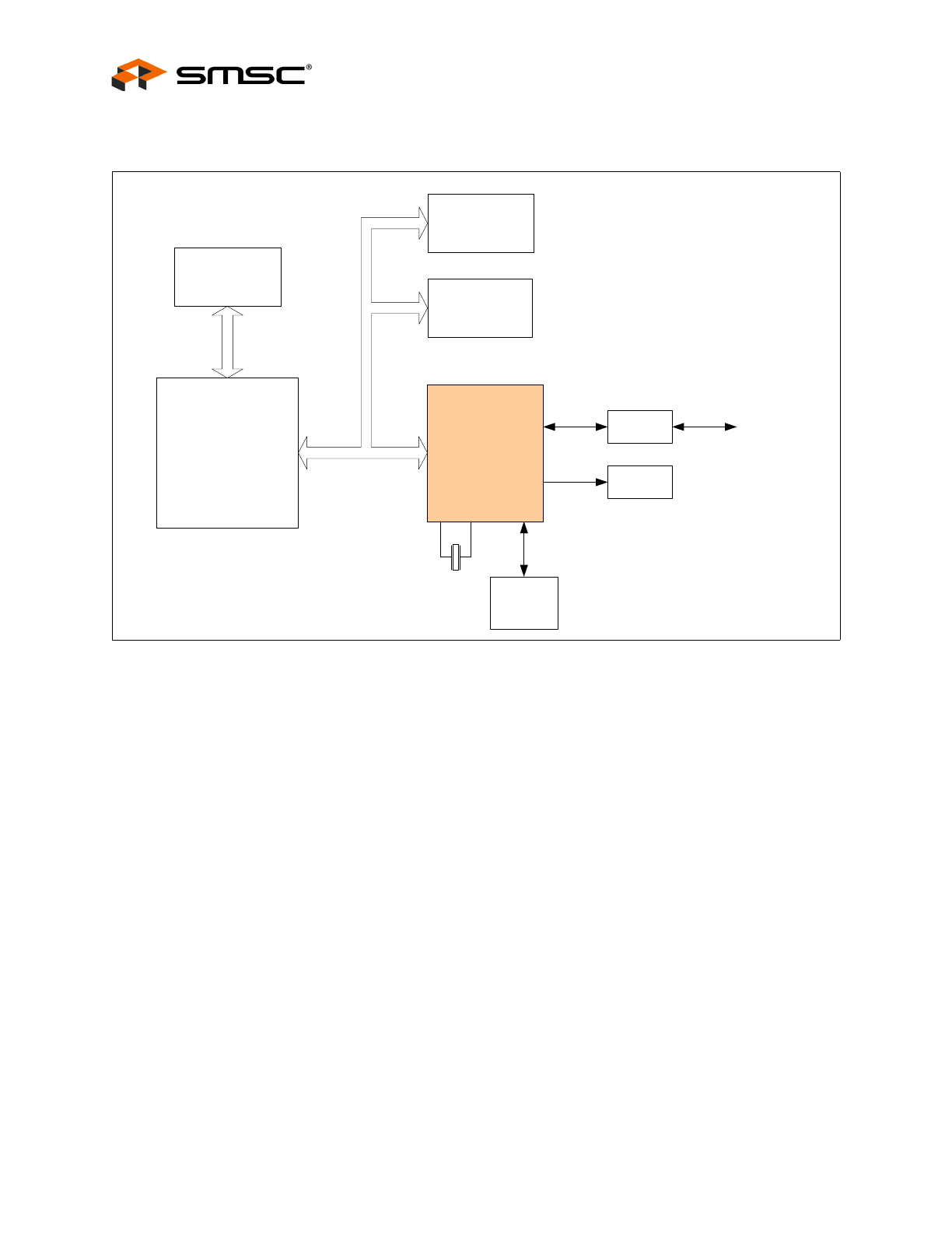
1.1
Block Diagram
The SMSC LAN9210 integrated 10/100 MAC/PHY controller is a peripheral chip that performs the
function of translating parallel data from a host controller into Ethernet packets. The LAN9210 Ethernet
MAC/PHY controller is designed and optimized to function in an embedded environment. All
communication is performed with programmed I/O transactions using the simple SRAM-like host
interface bus.
The diagram shown above, describes a typical system configuration of the LAN9210 in a typical
embedded environment.
The LAN9210 is a general purpose, platform independent, Ethernet controller. The LAN9210 consists
of four major functional blocks. The four blocks are:
10/100 Ethernet PHY
10/100 Ethernet MAC
RX/TX FIFOs
Host Bus Interface (HBI)
Figure 1.1 System Block Diagram
Microprocessor/
Microcontroller
LAN9210
Magnetics
Ethernet
System
Peripherals
System Memory
EEPROM
(Optional)
LEDS/GPIO
25MHz
XTAL
System Memory