
2017 Microchip Technology Inc.
DS20005826A-page 1
HV256
Features
• Thirty-two Independent High-voltage Amplifiers
• 300V Operating Voltage
• 295V Output Voltage
• 2.2V/µs Typical Output Slew Rate
• Adjustable Output Current Source Limit
• Adjustable Output Current Sink Limit
• Internal Closed-loop Gain of 72V/V
• 12 MΩ Feedback Impedance
• Layout Ideal for Die Applications
Applications
• Microelectromechanical Systems (MEMS) Driver
• Piezoelectric Transducer Driver
• Optical Crosspoint Switches
(Using MEMS Technology)
General Description
The HV256 is a 32-channel, high-voltage amplifier
array integrated circuit. It operates on a single
high-voltage supply, up to 300V, and two low-voltage
supplies, V
DD
and V
NN
.
The input voltage range is from 0V to 4.096V. The
internal closed-loop gain is 72V/V, giving an output
voltage of 295V when 4.096V is applied. Input voltages
of up to 5V can be applied but will cause the output to
saturate. The maximum output voltage swing is 5V
below the V
PP
high-voltage supply. The outputs can
drive capacitive loads of up to 3000 pF.
The maximum output source and sink currents can be
adjusted by using two external resistors. An external
R
SOURCE
resistor controls the maximum sourcing
current, and an external R
SINK
resistor controls the
maximum sinking current. The current limit is
approximately 12.5V divided by the external resistor
value. The setting is common for all 32 outputs. A
low-voltage silicon junction diode is made available to
help monitor the die temperature.
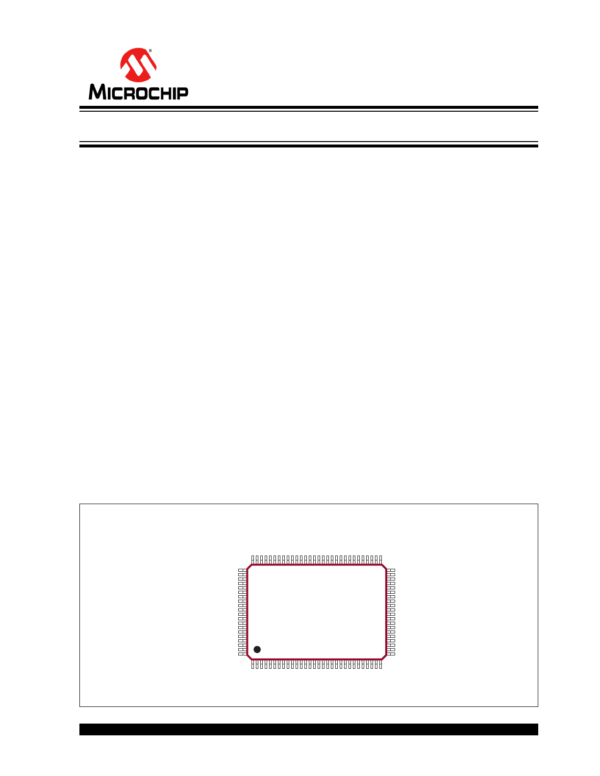
Package Type
100-lead MQFP
(Top view)
1
100
See
Table 3-1
for pin information.
32-Channel High-Voltage Amplifier Array
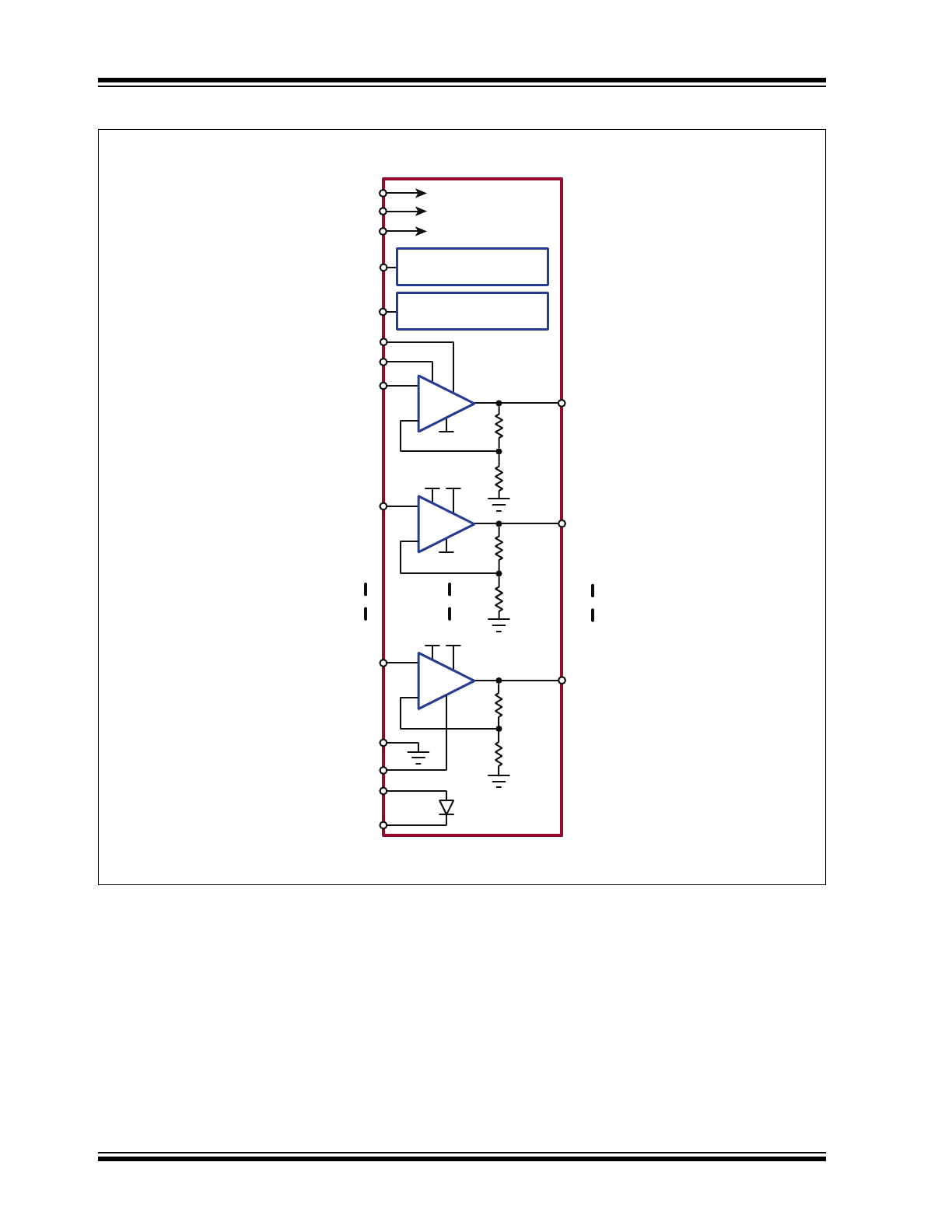
HV
OUT
0
HV
OUT
31
HV
OUT
1
GND
VPP
VNN
-
+
R
71R
VDD
VPP
-
+
VIN0
VPP
-
+
Output Current Source
Limiting for all HV
OUT
RSOURCE
R
R
RSINK
Output Current Sink
Limiting for all HV
OUT
71R
71R
Anode
Cathode
To internal VPP bus
BYP-VPP
BYP-VDD
BYP-VNN
To internal VNN bus
To internal VDD bus
VIN1
VIN31
VDD
VDD
VNN
VNN
HV256
DS20005826A-page 2
2017 Microchip Technology Inc.
Functional Block Diagram
2017 Microchip Technology Inc.
DS20005826A-page 3
HV256
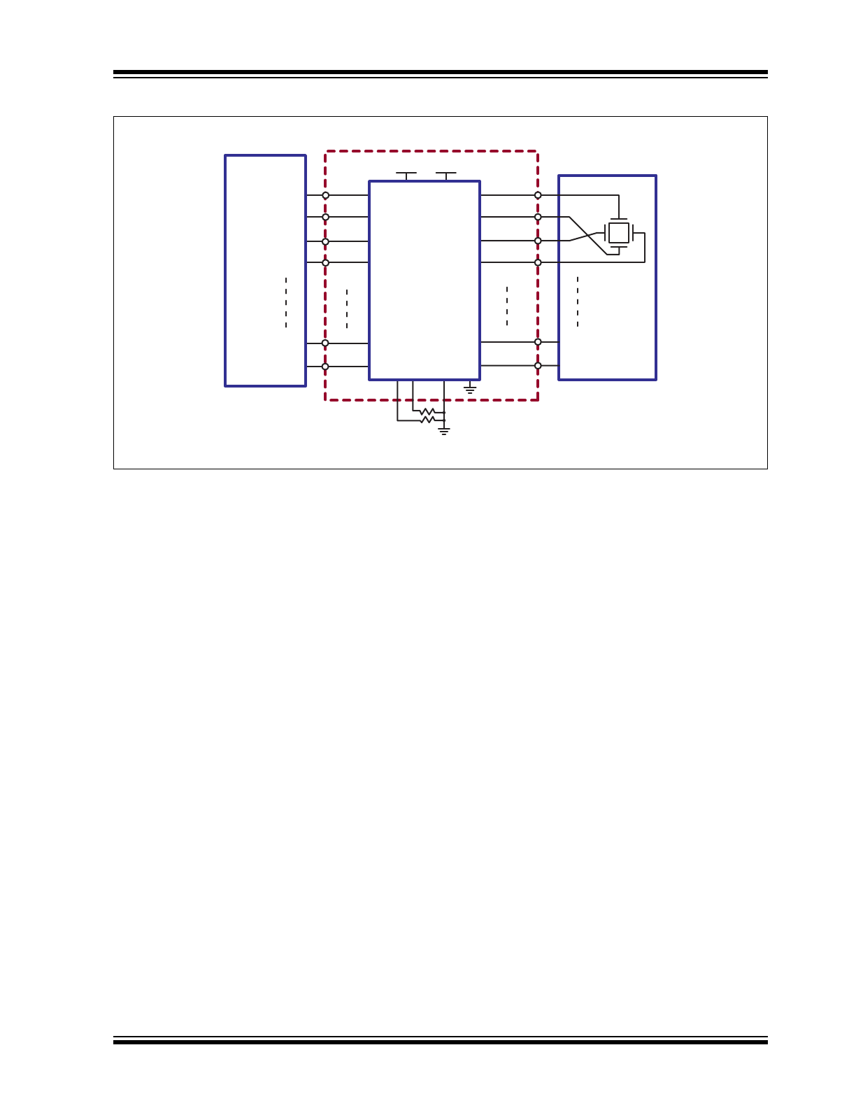
Typical Application Circuit
V
IN
0
V
IN
0
V
IN
0
V
IN
0
HV
OUT
0
HV
OUT
1
HV
OUT
2
HV
OUT
3
HV256
AGND
MEMS
Array
y
y
x
x
HV
OUT
30
HV
OUT
31
VNN
VDD
VPP
V
IN
30
V
IN
31
Micro
Processor
DAC
DAC
DAC
DAC
DAC
DAC
High Voltage
Op-Amp
Array
RSOURCE
RSINK
HV256
DS20005826A-page 4
2017 Microchip Technology Inc.
1.0
ELECTRICAL CHARACTERISTICS
Absolute Maximum Ratings†
High-voltage Supply, V
PP
....................................................................................................................................... 310V
Analog Low-voltage Positive Supply, AV
DD
................................................................................................................ 8V
Digital Low-voltage Positive Supply, DV
DD
................................................................................................................. 8V
Analog Low-voltage Negative Supply, AV
NN
............................................................................................................ –7V
Digital Low-voltage Negative Supply, DV
NN
............................................................................................................ –7V
Logic Input Voltage ................................................................................................................................. –0.5V to DV
DD
Analog Input Signal, V
IN
................................................................................................................................... 0V to 6V
Maximum Junction Temperature, T
J
..................................................................................................................... 150°C
Storage Temperature, T
S
.................................................................................................................... –65°C to +150°C
† Notice: Stresses above those listed under “Absolute Maximum Ratings” may cause permanent damage to the
device. This is a stress rating only, and functional operation of the device at those or any other conditions above those
indicated in the operational sections of this specification is not intended. Exposure to maximum rating conditions for
extended periods may affect device reliability.
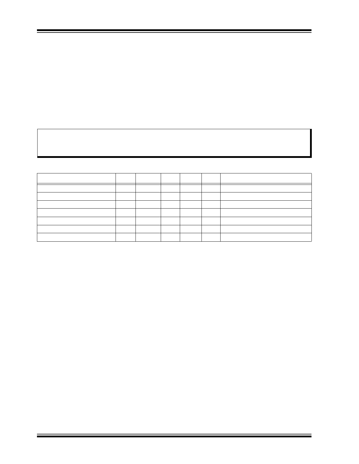
RECOMMENDED OPERATING CONDITIONS
Parameter
Sym.
Min.
Typ.
Max.
Unit
Conditions
High-voltage Positive Supply
V
PP
125
—
300
V
Low-voltage Positive Supply
V
DD
6
—
7.5
V
Low-voltage Negative Supply
V
NN
–4.5
—
–6.5
V
V
PP
Supply Current
I
PP
—
—
0.8
mA
V
PP
= 300V, All HV
OUT
= 0V, No load
V
DD
Supply Current
I
DD
—
—
5
mA
V
DD
= 6V to 7.5V
V
NN
Supply Current
I
NN
–6
—
—
mA
V
NN
= –4.5V to –6.5V
Operating Temperature Range
T
J
–10
—
85
°C
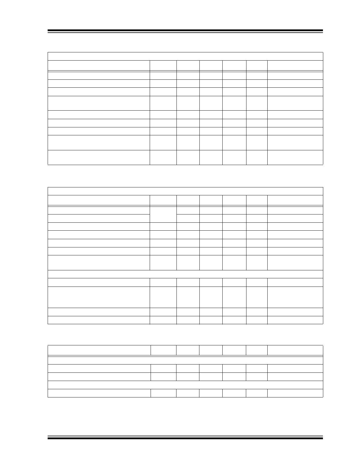
DC ELECTRICAL CHARACTERISTICS
Electrical Specifications: Over operating conditions unless otherwise noted.
Parameter
Sym.
Min.
Typ.
Max.
Unit
Conditions
HV
OUT
Voltage Swing
HV
OUT
0
—
V
PP
–5
V
Input Voltage Range
V
IN
0
—
5
V
Input Voltage Offset
V
INOS
—
—
±50
mV
Input referred
Feedback Resistance from HV
OUT
to Ground
R
FB
9.6
12
—
MΩ
HV
OUT
Capacitive Load
C
LOAD
0
—
3000
pF
HV
OUT
Sourcing Current Limiting Range
I
SOURCE
385
550
715
µA
R
SOURCE
= 25 kΩ
HV
OUT
Sinking Current Limiting Range
I
SINK
385
550
715
µA
R
SINK
= 25 kΩ
External Resistance Range
for Setting Maximum Current Source
R
SOURCE
25
—
250
kΩ
External Resistance Range for Setting
Maximum Current Sink
R
SINK
25
—
250
kΩ
AC ELECTRICAL CHARACTERISTICS
Electrical Specifications: Over operating conditions unless otherwise noted
Parameter
Sym.
Min.
Typ.
Max.
Unit
Conditions
HV
OUT
Slew Rate Rise
SR
—
2.2
—
V/µs
No load
HV
OUT
Slew Rate Fall
—
2
—
V/µs
No load
HV
OUT
–3 dB Channel Bandwidth
BW
—
4
—
kHz
V
PP
= 300V
Open-loop Gain
A
O
70
100
—
dB
Closed-loop Gain
A
V
68.4
72
75.6
V/V
DC Channel-to-channel Crosstalk
CT
DC
–80
—
—
dB
Power Supply Rejection Ratio for V
PP
,
V
DD
and V
NN
PSRR
–40
—
—
dB
TEMPERATURE DIODE
Peak Inverse Voltage
PIV
—
—
5
V
Cathode to anode
Forward Diode Drop
V
F
—
0.6
—
V
I
F
= 100 µA,
anode to
cathode at T
A
= 25°C
Forward Diode Current
I
F
—
—
100
µA
Anode to cathode
V
F
Temperature Coefficient
T
C
—
–2.2
—
mV/°C Anode to cathode
TEMPERATURE SPECIFICATIONS
Parameter
Sym.
Min.
Typ.
Max.
Unit
Conditions
TEMPERATURE RANGE
Maximum Junction Temperature
T
J
—
—
+150
°C
Storage Temperature
T
S
–65
—
+150
°C
PACKAGE THERMAL RESISTANCE
100-lead MQFP
JA
—
39
—
°C/W
2017 Microchip Technology Inc.
DS20005826A-page 5
HV256
HV256
DS20005826A-page 6
2017 Microchip Technology Inc.
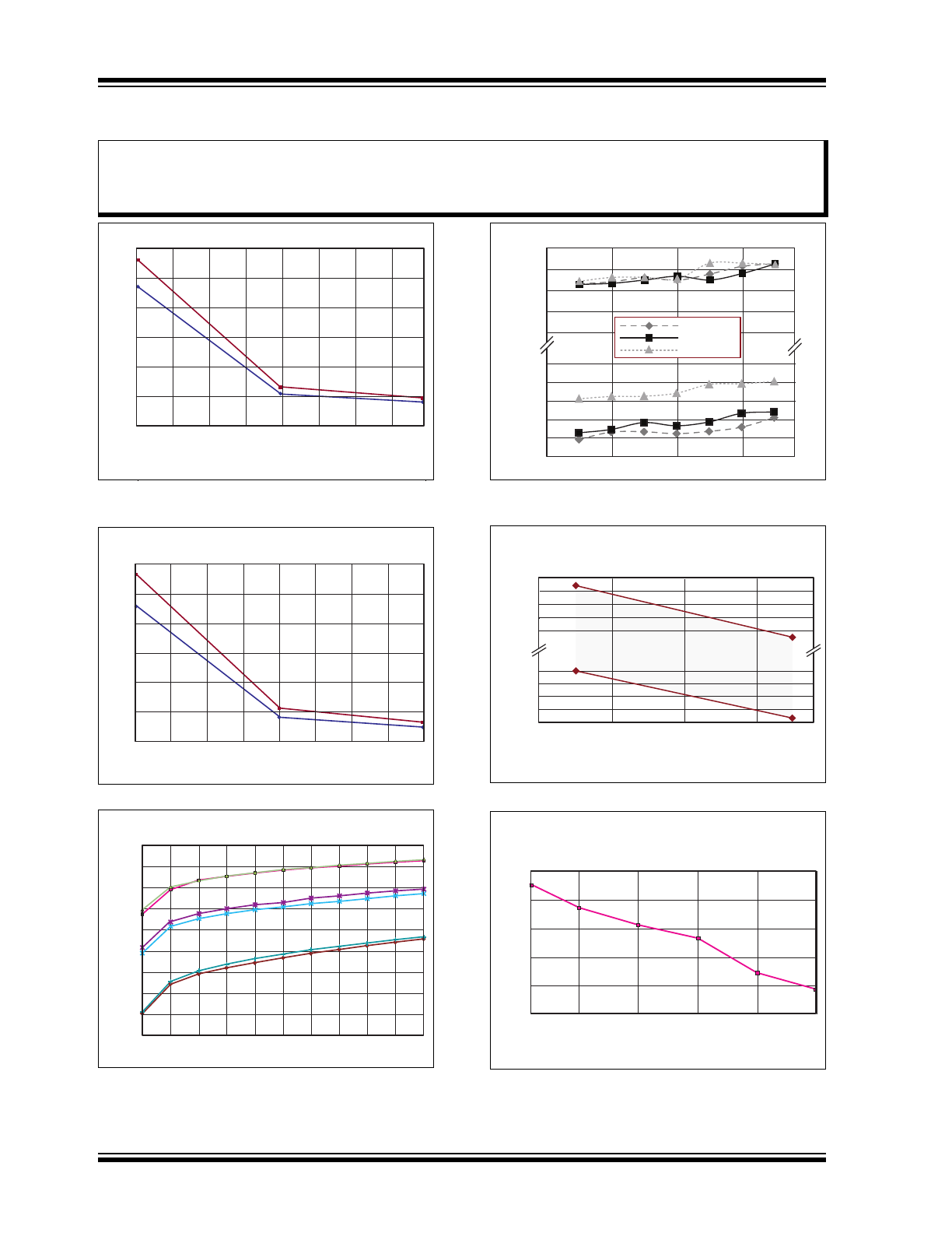
2.0
TYPICAL PERFORMANCE CURVES
(V
PP
= 300V, V
DD
= 6.5V, V
NN
= 5.5V, T
A
= 25
O
C)
R
SINK
(kΩ)
I
SINK
(μA)
min
max
600
500
400
300
200
100
0
25 150 250
Note:
The graphs and tables provided following this note are a statistical summary based on a limited number of
samples and are provided for informational purposes only. The performance characteristics listed herein
are not tested or guaranteed. In some graphs or tables, the data presented may be outside the specified
operating range (e.g. outside specified power supply range) and therefore outside the warranted range.
FIGURE 2-1:
I
SINK
vs. R
SINK
.
min
max
(V
PP
= 300V, V
DD
= 6.5V, V
NN
= 5.5V, T
A
= 25
O
C)
R
SOURCE
(kΩ)
I
SOURCE
(μA)
600
500
400
300
200
100
0
25 150 250
FIGURE 2-2:
I
SOURCE
vs. R
SOURCE
.
700
600
500
400
300
Diode Biasing Current (μA)
V
f
(mV)
(V
PP
= 300V, V
DD
= 6.5V, V
NN
= 5.5V)
-10
O
C
85
O
C
25
O
C
min
max
min
max
min
max
0 20 40 60 80 100
FIGURE 2-3:
Temperature Diode vs.
Temperature.
FIGURE 2-4:
Input Offset vs. V
IN
and
Temperature.
3.5
3.0
2.5
2.0
1.5
-2.0
-2.5
-3.0
-3.5
-4.0
-4.5
0 1.0 2.0 3.0 4.0
V
IN
(Volts)
Input Offset (mV)
Offset at -10
O
C
Offset at 25
O
C
Offset at 85
O
C
(V
PP
= 300V, V
DD
= 6.5V, V
NN
= 5.5V )
0 1 2 3 4
V
IN
(Volts)
Gain
(V
PP
= 300V, V
DD
= 6.5V, V
NN
= 5.5V, T
A
= -10
O
, +25
O
, +85
O
C)
73.97
73.96
73.95
73.94
73.93
72.73
72.72
72.71
72.70
72.69
FIGURE 2-5:
Gain vs. V
IN
.
Frequency (Hz)
-50
-40
-30
-20
-10
0
10 100 1k 10k 100k 1M
V
PP
PSRR (dB)
(V
PP
= 300V, V
DD
= 6.5V, V
NN
= 5.5V, T
A
= 25
O
C)
FIGURE 2-6:
V
PP
PSRR vs. Frequency.
2017 Microchip Technology Inc.
DS20005826A-page 7
HV256
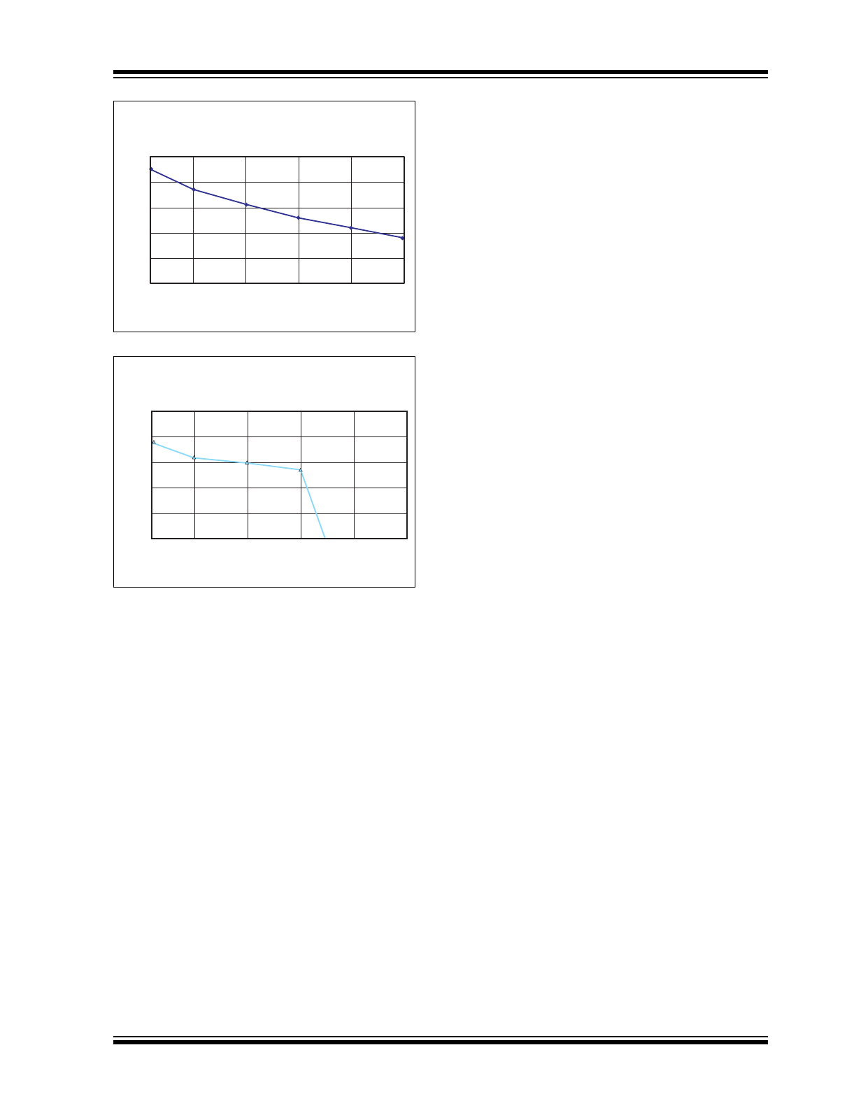
FIGURE 2-7:
Frequency (Hz)
V
DD
PSRR (dB)
(V
PP
= 300V, V
DD
= 6.5V, V
NN
= 5.5V, T
A
= 25
O
C)
-50
-40
-30
-20
-10
0
10 100 1K 10K 100K 1M
V
DD
PSRR vs. Frequency.
Frequency (Hz)
V
NN
PSRR (dB)
(V
PP
= 300V, V
DD
= 6.5V, V
NN
= 5.5V, T
A
= 25
O
C)
-50
-40
-30
-20
-10
0
10 100 1k 10k 100k 1M
FIGURE 2-8:
V
NN
PSRR vs. Frequency.
HV256
DS20005826A-page 8
2017 Microchip Technology Inc.
3.0
PIN DESCRIPTION
The details on the pins of HV256 are listed on
Table 3-1
. Refer to
Package Type
for the location of
pins.
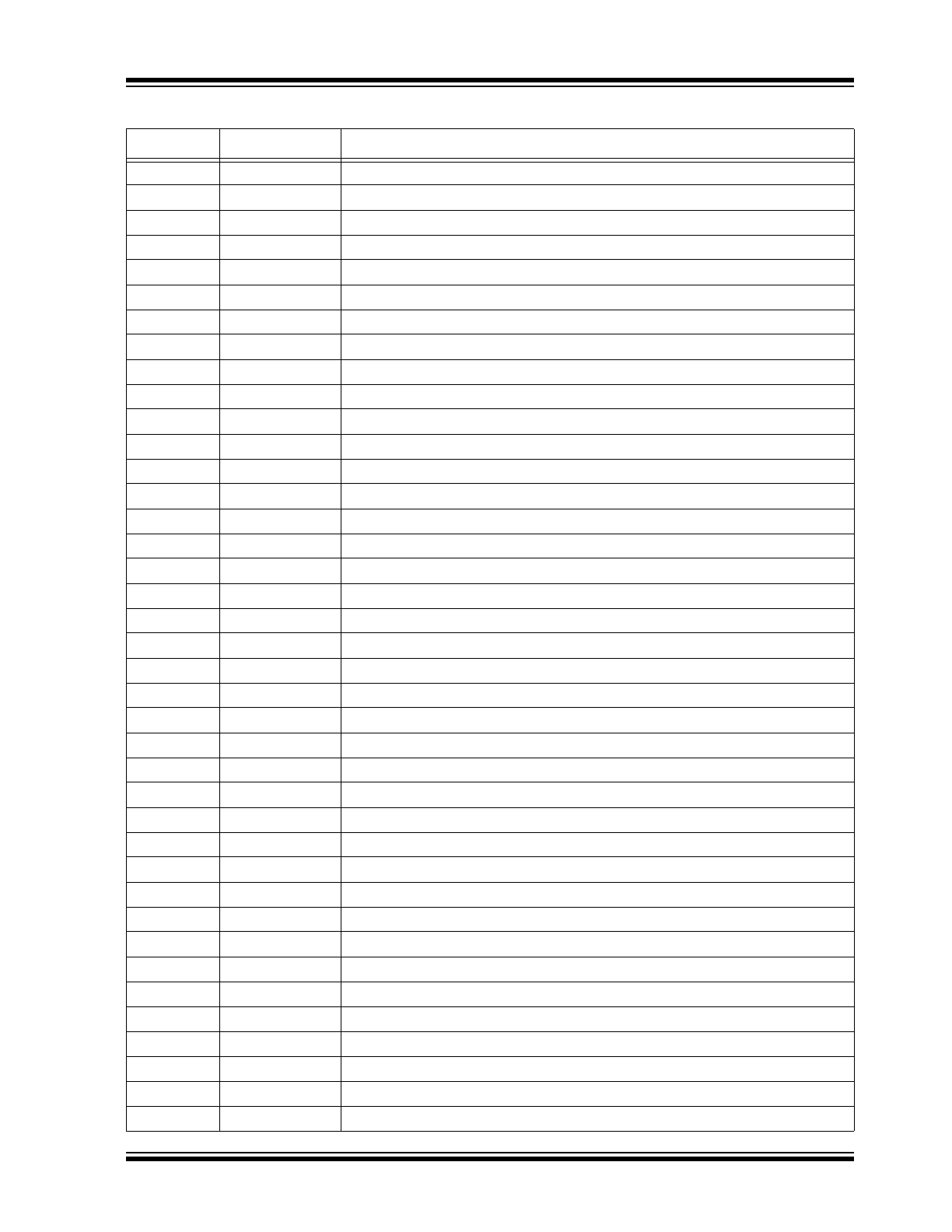
TABLE 3-1:
PIN FUNCTION TABLE
Pin Number
Pin Name
Description
1
HVOUT31
Amplifier output
2
HVOUT30
Amplifier output
3
HVOUT29
Amplifier output
4
HVOUT28
Amplifier output
5
HVOUT27
Amplifier output
6
HVOUT26
Amplifier output
7
HVOUT25
Amplifier output
8
HVOUT24
Amplifier output
9
HVOUT23
Amplifier output
10
HVOUT22
Amplifier output
11
HVOUT21
Amplifier output
12
HVOUT20
Amplifier output
13
HVOUT19
Amplifier output
14
HVOUT18
Amplifier output
15
HVOUT17
Amplifier output
16
HVOUT16
Amplifier output
17
HVOUT15
Amplifier output
18
HVOUT14
Amplifier output
19
HVOUT13
Amplifier output
20
HVOUT12
Amplifier output
21
HVOUT11
Amplifier output
22
HVOUT10
Amplifier output
23
HVOUT9
Amplifier output
24
HVOUT8
Amplifier output
25
HVOUT7
Amplifier output
26
HVOUT6
Amplifier output
27
HVOUT5
Amplifier output
28
HVOUT4
Amplifier output
29
HVOUT3
Amplifier output
30
HVOUT2
Amplifier output
31
HVOUT1
Amplifier output
32
HVOUT0
Amplifier output
33
VPP
High-voltage positive supply. There are two pads in the die pad diagram.
34
NC
No connect
35
NC
No connect
2017 Microchip Technology Inc.
DS20005826A-page 9
HV256
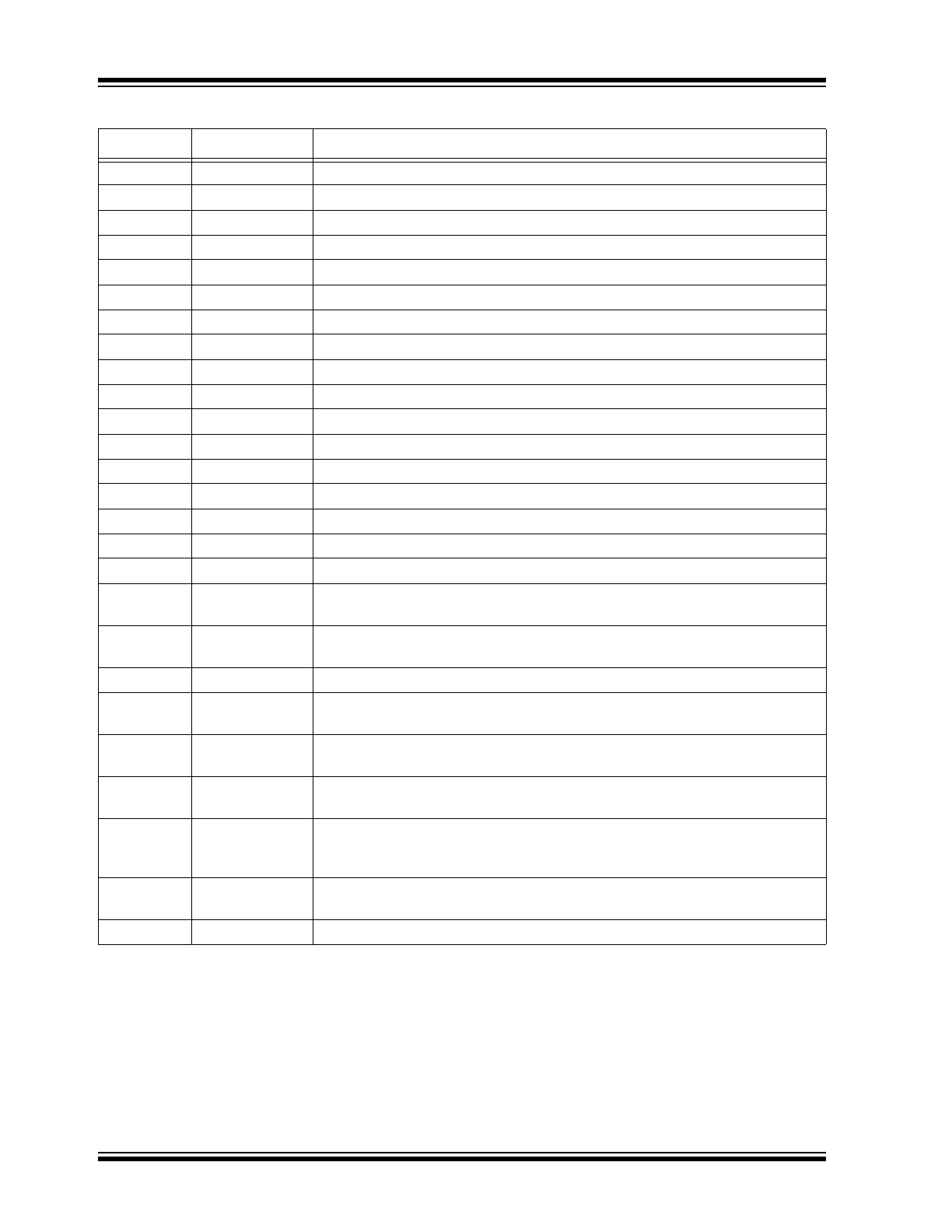
36
NC
No connect
37
NC
No connect
38
NC
No connect
39
GND
Digital ground. There are four pads in the die pad diagram.
40
VNN
Analog low-voltage negative supply. There are four pads in the die pad diagram.
41
NC
No connect
42
VDD
Analog low-voltage positive supply. There are four pads in the die pad diagram.
43
GND
Digital ground. There are four pads in the die pad diagram.
44
VNN
Analog low-voltage negative supply. There are four pads in the die pad diagram.
45
VDD
Analog low-voltage positive supply. There are four pads in the die pad diagram.
46
NC
No connect
47
NC
No connect
48
VIN0
Amplifier input
49
VIN1
Amplifier input
50
VIN2
Amplifier input
51
VIN3
Amplifier input
52
VIN4
Amplifier input
53
VIN5
Amplifier input
54
VIN6
Amplifier input
55
VIN7
Amplifier input
56
VIN8
Amplifier input
57
VIN9
Amplifier input
58
VIN10
Amplifier input
59
VIN11
Amplifier input
60
VIN12
Amplifier input
61
VIN13
Amplifier input
62
VIN14
Amplifier input
63
VIN15
Amplifier input
64
VIN16
Amplifier input
65
VIN17
Amplifier input
66
VIN18
Amplifier input
67
VIN19
Amplifier input
68
VIN20
Amplifier input
69
VIN21
Amplifier input
70
VIN22
Amplifier input
71
VIN23
Amplifier input
72
VIN24
Amplifier input
73
VIN25
Amplifier input
74
VIN26
Amplifier input
TABLE 3-1:
PIN FUNCTION TABLE (CONTINUED)
Pin Number
Pin Name
Description
HV256
DS20005826A-page 10
2017 Microchip Technology Inc.
75
VIN27
Amplifier input
76
VIN28
Amplifier input
77
VIN29
Amplifier input
78
VIN30
Amplifier input
79
VIN31
Amplifier input
80
NC
No connect
81
NC
No connect
82
NC
No connect
83
NC
No connect
84
NC
No connect
85
NC
No connect
86
GND
Digital ground. There are four pads in the die pad diagram.
87
VDD
Analog low-voltage positive supply. There are four pads in the die pad diagram.
88
VNN
Analog low-voltage negative supply. There are four pads in the die pad diagram.
89
GND
Digital ground. There are four pads in the die pad diagram.
90
NC
No connect
91
VDD
Analog low-voltage positive supply. There are four pads in the die pad diagram.
92
BYP-VNN
A low-voltage 1 nF to 10 nF decoupling capacitor across VNN and BYP-VNN is
required.
93
BYP-VDD
A low voltage 1 nF to 10 nF decoupling capacitor across VDD and BYP-VDD is
required.
94
VNN
Analog low-voltage negative supply. There are four pads in the die pad diagram.
95
ANODE
The anode side of a low-voltage silicon diode that can be used to monitor die
temperature
96
CATHODE
The cathode side of a low-voltage silicon diode that can be used to monitor die
temperature
97
RSINK
The external resistor from RSINK to VNN that sets the output current sinking limit.
The current limit is approximately 12.5V divided by the RSINK resistor value.
98
RSOURCE
The external resistor from RSOURCE to VNN that sets the output current
sourcing limit. The current limit is approximately 12.5V divided by the RSOURCE
resistor value.
99
BYP-VPP
A low-voltage 1 nF to 10 nF decoupling capacitor across VPP and BYP-VPP is
required.
100
VPP
High-voltage positive supply. There are four pads in the die pad diagram.
TABLE 3-1:
PIN FUNCTION TABLE (CONTINUED)
Pin Number
Pin Name
Description