

SMSC EMC6D102
DATASHEET
Revision 0.4 (09-25-07)
Datasheet
PRODUCT FEATURES
EMC6D102
Fan Control Device with
Hardware Monitoring and
Acoustic Noise Reduction
Features
3.3 Volt Operation (5 Volt Tolerant Input Buffers)
SMBus 2.0 compliant interface (Fixed, Not
Discoverable) With Three Slave Address Options
Fan Control
— PWM (Pulse width Modulation) Outputs (3)
— Fan Tachometer Inputs (4)
— Individual status and enable bits per tach input
— Programmable automatic fan control based on
temperature
— Fan ramp rate control for acoustic noise reduction
Temperature Monitor
— Monitoring of Two Remote Thermal Diodes (+/- 3 deg
C accuracy)
— Internal Ambient Temperature Measurement
— Limit Comparison of all Monitored Values
— Individual status and enable bits per thermal input
— Interrupt Pin for out-of-limit Temperature Indication
— Configurable offset for internal or external temperature
channels.
— Supports 4 programmable temperature averaging
modes
— 2 monitoring modes: Continuous or Cycle (Power
Saving mode)
— Offers 2 Low Power Modes when monitoring is off:
Sleep and Shutdown
Voltage Monitor
— Monitor Power supplies (+2.5V, +5V, +12V, Vccp, and
VCC)
— Individual status and enable bits per voltage input
— Limit Comparison of all Monitored Values
— Interrupt Pin for out-of-limit Voltage Indication
— Supports 4 programmable voltage averaging modes
— 2 monitoring modes: Continuous or Cycle (Power
Saving mode)
— Offers 2 Low Power Modes when monitoring is off:
Sleep and Shutdown
5 VID (Voltage Identification) inputs
XOR Tree test mode
24-pin, SSOP Lead-Free RoHS Compliant package

ORDER NUMBERS:
EMC6D102-CZC FOR 24 PIN SSOP LEAD-FREE ROHS COMPLIANT PACKAGE
EMC6D102-CZC-TR FOR 24 PIN SSOP LEAD-FREE ROHS COMPLIANT PACKAGE
Fan Control Device with Hardware Monitoring and Acoustic Noise Reduction Features
Datasheet
Revision 0.4 (09-25-07)
2
SMSC EMC6D102
DATASHEET
80 ARKAY DRIVE, HAUPPAUGE, NY 11788 (631) 435-6000, FAX (631) 273-3123
Copyright © 2007 SMSC or its subsidiaries. All rights reserved.
Circuit diagrams and other information relating to SMSC products are included as a means of illustrating typical applications. Consequently, complete information sufficient for
construction purposes is not necessarily given. Although the information has been checked and is believed to be accurate, no responsibility is assumed for inaccuracies. SMSC
reserves the right to make changes to specifications and product descriptions at any time without notice. Contact your local SMSC sales office to obtain the latest specifications
before placing your product order. The provision of this information does not convey to the purchaser of the described semiconductor devices any licenses under any patent
rights or other intellectual property rights of SMSC or others. All sales are expressly conditional on your agreement to the terms and conditions of the most recently dated
version of SMSC's standard Terms of Sale Agreement dated before the date of your order (the "Terms of Sale Agreement"). The product may contain design defects or errors
known as anomalies which may cause the product's functions to deviate from published specifications. Anomaly sheets are available upon request. SMSC products are not
designed, intended, authorized or warranted for use in any life support or other application where product failure could cause or contribute to personal injury or severe property
damage. Any and all such uses without prior written approval of an Officer of SMSC and further testing and/or modification will be fully at the risk of the customer. Copies of
this document or other SMSC literature, as well as the Terms of Sale Agreement, may be obtained by visiting SMSC’s website at http://www.smsc.com. SMSC is a registered
trademark of Standard Microsystems Corporation (“SMSC”). Product names and company names are the trademarks of their respective holders.
SMSC DISCLAIMS AND EXCLUDES ANY AND ALL WARRANTIES, INCLUDING WITHOUT LIMITATION ANY AND ALL IMPLIED WARRANTIES OF MERCHANTABILITY,
FITNESS FOR A PARTICULAR PURPOSE, TITLE, AND AGAINST INFRINGEMENT AND THE LIKE, AND ANY AND ALL WARRANTIES ARISING FROM ANY COURSE
OF DEALING OR USAGE OF TRADE. IN NO EVENT SHALL SMSC BE LIABLE FOR ANY DIRECT, INCIDENTAL, INDIRECT, SPECIAL, PUNITIVE, OR CONSEQUENTIAL
DAMAGES; OR FOR LOST DATA, PROFITS, SAVINGS OR REVENUES OF ANY KIND; REGARDLESS OF THE FORM OF ACTION, WHETHER BASED ON CONTRACT;
TORT; NEGLIGENCE OF SMSC OR OTHERS; STRICT LIABILITY; BREACH OF WARRANTY; OR OTHERWISE; WHETHER OR NOT ANY REMEDY OF BUYER IS HELD
TO HAVE FAILED OF ITS ESSENTIAL PURPOSE, AND WHETHER OR NOT SMSC HAS BEEN ADVISED OF THE POSSIBILITY OF SUCH DAMAGES.

Fan Control Device with Hardware Monitoring and Acoustic Noise Reduction Features
Datasheet
SMSC EMC6D102
3
Revision 0.4 (09-25-07)
DATASHEET
Table of Contents
Chapter 1 General Description. . . . . . . . . . . . . . . . . . . . . . . . . . . . . . . . . . . . . . . . . . . . . . . . . 8
Chapter 2 Pinout . . . . . . . . . . . . . . . . . . . . . . . . . . . . . . . . . . . . . . . . . . . . . . . . . . . . . . . . . . . . 9
Chapter 3 Pin Description. . . . . . . . . . . . . . . . . . . . . . . . . . . . . . . . . . . . . . . . . . . . . . . . . . . . 10
3.1
Pin Functions . . . . . . . . . . . . . . . . . . . . . . . . . . . . . . . . . . . . . . . . . . . . . . . . . . . . . . . . . . . . . . . . . 10
3.2
Buffer Type Description . . . . . . . . . . . . . . . . . . . . . . . . . . . . . . . . . . . . . . . . . . . . . . . . . . . . . . . . . 11
3.3
3.3V Operation, 5V Tolerance . . . . . . . . . . . . . . . . . . . . . . . . . . . . . . . . . . . . . . . . . . . . . . . . . . . . 12
Chapter 4 SMBus Interface . . . . . . . . . . . . . . . . . . . . . . . . . . . . . . . . . . . . . . . . . . . . . . . . . . 13
4.1
Slave Address. . . . . . . . . . . . . . . . . . . . . . . . . . . . . . . . . . . . . . . . . . . . . . . . . . . . . . . . . . . . . . . . . 13
4.2
Slave Bus Interface. . . . . . . . . . . . . . . . . . . . . . . . . . . . . . . . . . . . . . . . . . . . . . . . . . . . . . . . . . . . . 14
4.3
Bus Protocols . . . . . . . . . . . . . . . . . . . . . . . . . . . . . . . . . . . . . . . . . . . . . . . . . . . . . . . . . . . . . . . . . 14
4.4
Invalid Protocol Response Behavior. . . . . . . . . . . . . . . . . . . . . . . . . . . . . . . . . . . . . . . . . . . . . . . . 15
4.4.1
Undefined Registers . . . . . . . . . . . . . . . . . . . . . . . . . . . . . . . . . . . . . . . . . . . . . . . . . . . . 15
4.5
General Call Address Response . . . . . . . . . . . . . . . . . . . . . . . . . . . . . . . . . . . . . . . . . . . . . . . . . . 15
4.6
Slave Device Time-Out. . . . . . . . . . . . . . . . . . . . . . . . . . . . . . . . . . . . . . . . . . . . . . . . . . . . . . . . . . 16
4.7
Stretching the SCLK Signal . . . . . . . . . . . . . . . . . . . . . . . . . . . . . . . . . . . . . . . . . . . . . . . . . . . . . . 16
4.8
SMBus Timing . . . . . . . . . . . . . . . . . . . . . . . . . . . . . . . . . . . . . . . . . . . . . . . . . . . . . . . . . . . . . . . . 16
4.9
Bus Reset Sequence . . . . . . . . . . . . . . . . . . . . . . . . . . . . . . . . . . . . . . . . . . . . . . . . . . . . . . . . . . . 16
4.10 SMBus Alert Response Address . . . . . . . . . . . . . . . . . . . . . . . . . . . . . . . . . . . . . . . . . . . . . . . . . . 16
Chapter 5 Hardware Monitoring . . . . . . . . . . . . . . . . . . . . . . . . . . . . . . . . . . . . . . . . . . . . . . 18
5.1
Input Monitoring . . . . . . . . . . . . . . . . . . . . . . . . . . . . . . . . . . . . . . . . . . . . . . . . . . . . . . . . . . . . . . . 18
5.2
Resetting the EMC6D102 . . . . . . . . . . . . . . . . . . . . . . . . . . . . . . . . . . . . . . . . . . . . . . . . . . . . . . . . 18
5.2.1
Power-On Reset . . . . . . . . . . . . . . . . . . . . . . . . . . . . . . . . . . . . . . . . . . . . . . . . . . . . . . . 18
5.2.2
Soft Reset (Initialization) . . . . . . . . . . . . . . . . . . . . . . . . . . . . . . . . . . . . . . . . . . . . . . . . . 18
5.3
Monitoring Modes . . . . . . . . . . . . . . . . . . . . . . . . . . . . . . . . . . . . . . . . . . . . . . . . . . . . . . . . . . . . . . 18
5.3.1
Continuous Monitoring Mode. . . . . . . . . . . . . . . . . . . . . . . . . . . . . . . . . . . . . . . . . . . . . . 19
5.3.2
Cycle Monitoring Mode . . . . . . . . . . . . . . . . . . . . . . . . . . . . . . . . . . . . . . . . . . . . . . . . . . 20
5.4
Interrupt Status Registers . . . . . . . . . . . . . . . . . . . . . . . . . . . . . . . . . . . . . . . . . . . . . . . . . . . . . . . . 21
5.4.1
Diode Fault . . . . . . . . . . . . . . . . . . . . . . . . . . . . . . . . . . . . . . . . . . . . . . . . . . . . . . . . . . . 22
5.5
Interrupt Pin . . . . . . . . . . . . . . . . . . . . . . . . . . . . . . . . . . . . . . . . . . . . . . . . . . . . . . . . . . . . . . . . . . 23
5.6
Low Power Modes . . . . . . . . . . . . . . . . . . . . . . . . . . . . . . . . . . . . . . . . . . . . . . . . . . . . . . . . . . . . . 24
5.6.1
Sleep Mode . . . . . . . . . . . . . . . . . . . . . . . . . . . . . . . . . . . . . . . . . . . . . . . . . . . . . . . . . . . 24
5.6.2
Shutdown Mode. . . . . . . . . . . . . . . . . . . . . . . . . . . . . . . . . . . . . . . . . . . . . . . . . . . . . . . . 24
5.7
Analog Voltage Measurement . . . . . . . . . . . . . . . . . . . . . . . . . . . . . . . . . . . . . . . . . . . . . . . . . . . . 24
5.8
Voltage ID . . . . . . . . . . . . . . . . . . . . . . . . . . . . . . . . . . . . . . . . . . . . . . . . . . . . . . . . . . . . . . . . . . . . 25
5.9
Temperature Measurement . . . . . . . . . . . . . . . . . . . . . . . . . . . . . . . . . . . . . . . . . . . . . . . . . . . . . . 25
5.9.1
Internal Temperature Measurement . . . . . . . . . . . . . . . . . . . . . . . . . . . . . . . . . . . . . . . . 25
5.9.2
External Temperature Measurement . . . . . . . . . . . . . . . . . . . . . . . . . . . . . . . . . . . . . . . . 25
5.9.3
Temperature Data Format . . . . . . . . . . . . . . . . . . . . . . . . . . . . . . . . . . . . . . . . . . . . . . . . 26
5.9.4
Offset Registers. . . . . . . . . . . . . . . . . . . . . . . . . . . . . . . . . . . . . . . . . . . . . . . . . . . . . . . . 27
5.10 Thermal Zones . . . . . . . . . . . . . . . . . . . . . . . . . . . . . . . . . . . . . . . . . . . . . . . . . . . . . . . . . . . . . . . . 27
Chapter 6 Fan Control . . . . . . . . . . . . . . . . . . . . . . . . . . . . . . . . . . . . . . . . . . . . . . . . . . . . . . 28
6.1
General Description . . . . . . . . . . . . . . . . . . . . . . . . . . . . . . . . . . . . . . . . . . . . . . . . . . . . . . . . . . . . 28
6.1.1
Limit and Configuration Registers . . . . . . . . . . . . . . . . . . . . . . . . . . . . . . . . . . . . . . . . . . 28
6.1.2
Device Set-Up . . . . . . . . . . . . . . . . . . . . . . . . . . . . . . . . . . . . . . . . . . . . . . . . . . . . . . . . . 28
6.1.3
PWM Fan Speed Control. . . . . . . . . . . . . . . . . . . . . . . . . . . . . . . . . . . . . . . . . . . . . . . . . 29
6.1.4
Fan Speed Monitoring . . . . . . . . . . . . . . . . . . . . . . . . . . . . . . . . . . . . . . . . . . . . . . . . . . . 37

Fan Control Device with Hardware Monitoring and Acoustic Noise Reduction Features
Datasheet
Revision 0.4 (09-25-07)
4
SMSC EMC6D102
DATASHEET
6.1.5
Linking Fan Tachometers to PWMs. . . . . . . . . . . . . . . . . . . . . . . . . . . . . . . . . . . . . . . . . 43
Chapter 7 Register Set. . . . . . . . . . . . . . . . . . . . . . . . . . . . . . . . . . . . . . . . . . . . . . . . . . . . . . . 45
7.1
Undefined Registers . . . . . . . . . . . . . . . . . . . . . . . . . . . . . . . . . . . . . . . . . . . . . . . . . . . . . . . . . . . . 47
7.2
Defined Registers . . . . . . . . . . . . . . . . . . . . . . . . . . . . . . . . . . . . . . . . . . . . . . . . . . . . . . . . . . . . . . 48
7.2.1
Register 10h: SMSC Test Register . . . . . . . . . . . . . . . . . . . . . . . . . . . . . . . . . . . . . . . . . 48
7.2.2
Register 1Dh, 1Eh, 1Fh: Offset Registers . . . . . . . . . . . . . . . . . . . . . . . . . . . . . . . . . . . . 48
7.2.3
Registers 20-24h: Voltage Reading. . . . . . . . . . . . . . . . . . . . . . . . . . . . . . . . . . . . . . . . . 48
7.2.4
Registers 25-27h: Temperature Reading . . . . . . . . . . . . . . . . . . . . . . . . . . . . . . . . . . . . 49
7.2.5
Registers 28-2Fh: Fan Tachometer Reading . . . . . . . . . . . . . . . . . . . . . . . . . . . . . . . . . 50
7.2.6
Registers 30-32h: Current PWM Duty . . . . . . . . . . . . . . . . . . . . . . . . . . . . . . . . . . . . . . . 51
7.2.7
Register 3Eh: Company ID . . . . . . . . . . . . . . . . . . . . . . . . . . . . . . . . . . . . . . . . . . . . . . . 52
7.2.8
Register 3Fh: Version / Stepping. . . . . . . . . . . . . . . . . . . . . . . . . . . . . . . . . . . . . . . . . . . 52
7.2.9
Register 40h: Ready/Lock/Start Monitoring . . . . . . . . . . . . . . . . . . . . . . . . . . . . . . . . . . . 53
7.2.10
Register 41h: Interrupt Status Register 1 . . . . . . . . . . . . . . . . . . . . . . . . . . . . . . . . . . . . 54
7.2.11
Register 42h: Interrupt Status Register 2 . . . . . . . . . . . . . . . . . . . . . . . . . . . . . . . . . . . . 55
7.2.12
Register 43h: VID . . . . . . . . . . . . . . . . . . . . . . . . . . . . . . . . . . . . . . . . . . . . . . . . . . . . . . 56
7.2.13
Registers 44-4Dh: Voltage Limit Registers . . . . . . . . . . . . . . . . . . . . . . . . . . . . . . . . . . . 57
7.2.14
Registers 4E-53h: Temperature Limit Registers . . . . . . . . . . . . . . . . . . . . . . . . . . . . . . . 57
7.2.15
Registers 54-5Bh: Fan Tachometer Low Limit . . . . . . . . . . . . . . . . . . . . . . . . . . . . . . . . 58
7.2.16
Registers 5C-5Eh: PWM Configuration . . . . . . . . . . . . . . . . . . . . . . . . . . . . . . . . . . . . . . 59
7.2.17
Registers 5F-61h: Zone Temperature Range, PWM Frequency . . . . . . . . . . . . . . . . . . . 60
7.2.18
Register 62h, 63h: Min/Off, PWM Ramp Rate Control . . . . . . . . . . . . . . . . . . . . . . . . . . 62
7.2.19
Registers 64-66h: Minimum PWM Duty Cycle. . . . . . . . . . . . . . . . . . . . . . . . . . . . . . . . . 63
7.2.20
Registers 67-69h: Zone Low Temperature Limit . . . . . . . . . . . . . . . . . . . . . . . . . . . . . . . 64
7.2.21
Registers 6A-6Ch: Absolute Temperature Limit . . . . . . . . . . . . . . . . . . . . . . . . . . . . . . . 65
7.2.22
Registers 6D-6Eh: Zone Hysteresis Registers . . . . . . . . . . . . . . . . . . . . . . . . . . . . . . . . 66
7.2.23
Register 6F: XOR Test Register . . . . . . . . . . . . . . . . . . . . . . . . . . . . . . . . . . . . . . . . . . . 67
7.2.24
Register 79h: SMSC Test Register . . . . . . . . . . . . . . . . . . . . . . . . . . . . . . . . . . . . . . . . . 67
7.2.25
Register 7Ah: SMSC Test Register . . . . . . . . . . . . . . . . . . . . . . . . . . . . . . . . . . . . . . . . . 67
7.2.26
Register 7Bh: SMSC Test Register . . . . . . . . . . . . . . . . . . . . . . . . . . . . . . . . . . . . . . . . . 67
7.2.27
Register 7Ch: Special Function Register. . . . . . . . . . . . . . . . . . . . . . . . . . . . . . . . . . . . . 68
7.2.28
Register 7Eh: Interrupt Enable 1 Register . . . . . . . . . . . . . . . . . . . . . . . . . . . . . . . . . . . . 69
7.2.29
Register 7Fh: Configuration Register . . . . . . . . . . . . . . . . . . . . . . . . . . . . . . . . . . . . . . . 69
7.2.30
Register 80h: Interrupt Enable 2 Register . . . . . . . . . . . . . . . . . . . . . . . . . . . . . . . . . . . . 70
7.2.31
Register 81h: TACH_PWM Association Register . . . . . . . . . . . . . . . . . . . . . . . . . . . . . . 71
7.2.32
Register 82h: Interrupt Enable 3 Register . . . . . . . . . . . . . . . . . . . . . . . . . . . . . . . . . . . . 71
7.2.33
Registers 85h-88h: A/D Converter LSbs Registers . . . . . . . . . . . . . . . . . . . . . . . . . . . . 72
7.2.34
Register 89h: SMSC Test Register . . . . . . . . . . . . . . . . . . . . . . . . . . . . . . . . . . . . . . . . . 73
7.2.35
Registers 8Ah: SMSC Test Register . . . . . . . . . . . . . . . . . . . . . . . . . . . . . . . . . . . . . . . . 73
7.2.36
Registers 8Bh: SMSC Test Register . . . . . . . . . . . . . . . . . . . . . . . . . . . . . . . . . . . . . . . . 73
7.2.37
Registers 8Ch: SMSC Test Register . . . . . . . . . . . . . . . . . . . . . . . . . . . . . . . . . . . . . . . . 73
7.2.38
Registers 8Dh: SMSC Test Register . . . . . . . . . . . . . . . . . . . . . . . . . . . . . . . . . . . . . . . . 73
7.2.39
Registers 8Eh: SMSC Test Register . . . . . . . . . . . . . . . . . . . . . . . . . . . . . . . . . . . . . . . . 73
7.2.40
Registers 90h-93h: TachX Option Registers . . . . . . . . . . . . . . . . . . . . . . . . . . . . . . . . . . 74
7.2.41
Registers 94h-96h: PWMx Option Registers . . . . . . . . . . . . . . . . . . . . . . . . . . . . . . . . . . 75
7.2.42
Register 97h: SMSC Test Register . . . . . . . . . . . . . . . . . . . . . . . . . . . . . . . . . . . . . . . . . 75
7.2.43
Register 98h:SMSC Test Register . . . . . . . . . . . . . . . . . . . . . . . . . . . . . . . . . . . . . . . . . 76
7.2.44
Register FFh: SMSC Test Register . . . . . . . . . . . . . . . . . . . . . . . . . . . . . . . . . . . . . . . . . 76
Chapter 8 Operational Description . . . . . . . . . . . . . . . . . . . . . . . . . . . . . . . . . . . . . . . . . . . . 77
8.1
Maximum Guaranteed Ratings . . . . . . . . . . . . . . . . . . . . . . . . . . . . . . . . . . . . . . . . . . . . . . . . . . . . 77
8.2
Ratings for Operation . . . . . . . . . . . . . . . . . . . . . . . . . . . . . . . . . . . . . . . . . . . . . . . . . . . . . . . . . . . 77

Fan Control Device with Hardware Monitoring and Acoustic Noise Reduction Features
Datasheet
SMSC EMC6D102
5
Revision 0.4 (09-25-07)
DATASHEET
Chapter 9 Timing Diagrams . . . . . . . . . . . . . . . . . . . . . . . . . . . . . . . . . . . . . . . . . . . . . . . . . . 80
9.1
PWM Outputs . . . . . . . . . . . . . . . . . . . . . . . . . . . . . . . . . . . . . . . . . . . . . . . . . . . . . . . . . . . . . . . . . 80
9.2
SMBus Interface . . . . . . . . . . . . . . . . . . . . . . . . . . . . . . . . . . . . . . . . . . . . . . . . . . . . . . . . . . . . . . . 80
Chapter 10 Mechanical Specifications . . . . . . . . . . . . . . . . . . . . . . . . . . . . . . . . . . . . . . . . . . . 82
Appendix A ADC Voltage Conversion . . . . . . . . . . . . . . . . . . . . . . . . . . . . . . . . . . . . . . . . . . . 83
Appendix B Example Fan Circuits . . . . . . . . . . . . . . . . . . . . . . . . . . . . . . . . . . . . . . . . . . . . . . 85

Fan Control Device with Hardware Monitoring and Acoustic Noise Reduction Features
Datasheet
Revision 0.4 (09-25-07)
6
SMSC EMC6D102
DATASHEET
List of Figures
Figure 2.1 EMC6D102 Pin Diagram . . . . . . . . . . . . . . . . . . . . . . . . . . . . . . . . . . . . . . . . . . . . . . . . . . . . . 9
Figure 4.1 Address Selection on EMC6D102 . . . . . . . . . . . . . . . . . . . . . . . . . . . . . . . . . . . . . . . . . . . . . 14
Figure 5.1 Interrupt Control . . . . . . . . . . . . . . . . . . . . . . . . . . . . . . . . . . . . . . . . . . . . . . . . . . . . . . . . . . . 22
Figure 6.1 Automatic Fan Control Flow Diagram . . . . . . . . . . . . . . . . . . . . . . . . . . . . . . . . . . . . . . . . . . 31
Figure 6.2 Automatic Fan Control . . . . . . . . . . . . . . . . . . . . . . . . . . . . . . . . . . . . . . . . . . . . . . . . . . . . . . 33
Figure 6.3 Spin Up Reduction Enabled . . . . . . . . . . . . . . . . . . . . . . . . . . . . . . . . . . . . . . . . . . . . . . . . . . 34
Figure 6.4 Illustration of PWM Ramp Rate Control . . . . . . . . . . . . . . . . . . . . . . . . . . . . . . . . . . . . . . . . . 36
Figure 6.5 PWM and Tachometer Concept. . . . . . . . . . . . . . . . . . . . . . . . . . . . . . . . . . . . . . . . . . . . . . . 39
Figure 7.1 Fan Activity Above Fan Temp Limit . . . . . . . . . . . . . . . . . . . . . . . . . . . . . . . . . . . . . . . . . . . . 61
Figure 9.1 PWMx Output Timing . . . . . . . . . . . . . . . . . . . . . . . . . . . . . . . . . . . . . . . . . . . . . . . . . . . . . . . 80
Figure 9.2 SMBus Timing . . . . . . . . . . . . . . . . . . . . . . . . . . . . . . . . . . . . . . . . . . . . . . . . . . . . . . . . . . . . 80
Figure 10.1 24-Pin SSOP Package Outline, 0.150 Wide Body, 0.025 Pitch . . . . . . . . . . . . . . . . . . . . . . . 82
Figure B.1 Fan Drive Circuitry (Apply to PWM Driving Two Fans) . . . . . . . . . . . . . . . . . . . . . . . . . . . . . 85
Figure B.2 Fan Drive Circuitry (Apply to PWM Driving One Fan) . . . . . . . . . . . . . . . . . . . . . . . . . . . . . . 85
Figure B.3 Fan Tachometer Circuitry (Apply to Each Fan) . . . . . . . . . . . . . . . . . . . . . . . . . . . . . . . . . . . 86
Figure B.4 Remote Diode (Apply to Remote2 Lines). . . . . . . . . . . . . . . . . . . . . . . . . . . . . . . . . . . . . . . . 86
Figure B.5 Suggested Minimum Track Width and Spacing . . . . . . . . . . . . . . . . . . . . . . . . . . . . . . . . . . . 86

Fan Control Device with Hardware Monitoring and Acoustic Noise Reduction Features
Datasheet
SMSC EMC6D102
7
Revision 0.4 (09-25-07)
DATASHEET
List of Tables
Table 3.1 EMC6D102 Pin Description . . . . . . . . . . . . . . . . . . . . . . . . . . . . . . . . . . . . . . . . . . . . . . . . . . . 10
Table 3.2 Buffer Type Descriptions . . . . . . . . . . . . . . . . . . . . . . . . . . . . . . . . . . . . . . . . . . . . . . . . . . . . . 11
Table 4.1 SMBus Slave Address Options . . . . . . . . . . . . . . . . . . . . . . . . . . . . . . . . . . . . . . . . . . . . . . . . 13
Table 4.2 SMBus Write Byte Protocol . . . . . . . . . . . . . . . . . . . . . . . . . . . . . . . . . . . . . . . . . . . . . . . . . . . 15
Table 4.3 SMBus Read Byte Protocol . . . . . . . . . . . . . . . . . . . . . . . . . . . . . . . . . . . . . . . . . . . . . . . . . . . 15
Table 4.4 Modified SMBus Receive Byte Protocol Response to ARA. . . . . . . . . . . . . . . . . . . . . . . . . . . 16
Table 5.1 AVG[2:0] Bit Decoder . . . . . . . . . . . . . . . . . . . . . . . . . . . . . . . . . . . . . . . . . . . . . . . . . . . . . . . 19
Table 5.2 Conversion Cycle Timing. . . . . . . . . . . . . . . . . . . . . . . . . . . . . . . . . . . . . . . . . . . . . . . . . . . . . 19
Table 5.3 ADC Conversion Sequence. . . . . . . . . . . . . . . . . . . . . . . . . . . . . . . . . . . . . . . . . . . . . . . . . . . 20
Table 5.4 Low Power Mode Control Bits . . . . . . . . . . . . . . . . . . . . . . . . . . . . . . . . . . . . . . . . . . . . . . . . . 24
Table 5.5 Min/Max ADC Conversion Table . . . . . . . . . . . . . . . . . . . . . . . . . . . . . . . . . . . . . . . . . . . . . . . 25
Table 5.6 Temperature Data Format . . . . . . . . . . . . . . . . . . . . . . . . . . . . . . . . . . . . . . . . . . . . . . . . . . . . 26
Table 6.1 PWM Ramp Rate. . . . . . . . . . . . . . . . . . . . . . . . . . . . . . . . . . . . . . . . . . . . . . . . . . . . . . . . . . . 35
Table 6.2 Max Tachometer Count Values for Different Stretch Periods . . . . . . . . . . . . . . . . . . . . . . . . . 41
Table 6.3 Minimum RPM Detectable Using 3 Edges – No PWM Stretching . . . . . . . . . . . . . . . . . . . . . . 41
Table 6.4 Minimum RPM Detectable Using 2 Edges – No PWM Stretching . . . . . . . . . . . . . . . . . . . . . . 42
Table 6.5 Minimum RPM Detectable– With PWM Stretching . . . . . . . . . . . . . . . . . . . . . . . . . . . . . . . . . 43
Table 7.1 Register Summary . . . . . . . . . . . . . . . . . . . . . . . . . . . . . . . . . . . . . . . . . . . . . . . . . . . . . . . . . . 45
Table 7.2 Voltage vs. Register Reading . . . . . . . . . . . . . . . . . . . . . . . . . . . . . . . . . . . . . . . . . . . . . . . . . 49
Table 7.3 Temperature vs. Register Reading . . . . . . . . . . . . . . . . . . . . . . . . . . . . . . . . . . . . . . . . . . . . . 50
Table 7.4 PWM Duty vs Register Reading . . . . . . . . . . . . . . . . . . . . . . . . . . . . . . . . . . . . . . . . . . . . . . . 52
Table 7.6 Temperature Limits vs. Register Settings . . . . . . . . . . . . . . . . . . . . . . . . . . . . . . . . . . . . . . . . 58
Table 7.7 Fan Zone Setting . . . . . . . . . . . . . . . . . . . . . . . . . . . . . . . . . . . . . . . . . . . . . . . . . . . . . . . . . . . 59
Table 7.8 Fan Spin-Up Register . . . . . . . . . . . . . . . . . . . . . . . . . . . . . . . . . . . . . . . . . . . . . . . . . . . . . . . 60
Table 7.9 Register Setting vs. PWM Frequency . . . . . . . . . . . . . . . . . . . . . . . . . . . . . . . . . . . . . . . . . . . 61
Table 7.10 Register Setting vs. Temperature Range . . . . . . . . . . . . . . . . . . . . . . . . . . . . . . . . . . . . . . . . 62
Table 7.11 PWM output below Limit depending on value of Off/Min . . . . . . . . . . . . . . . . . . . . . . . . . . . . . 62
Table 7.12 PWM Ramp Rate Control . . . . . . . . . . . . . . . . . . . . . . . . . . . . . . . . . . . . . . . . . . . . . . . . . . . . 63
Table 7.13 PWM Duty vs. Register Setting . . . . . . . . . . . . . . . . . . . . . . . . . . . . . . . . . . . . . . . . . . . . . . . . 64
Table 7.14 Temperature Limit vs. Register Setting . . . . . . . . . . . . . . . . . . . . . . . . . . . . . . . . . . . . . . . . . . 65
Table 7.15 Absolute Limit vs. Register Setting . . . . . . . . . . . . . . . . . . . . . . . . . . . . . . . . . . . . . . . . . . . . . 66
Table 7.16 Hysteresis Settings . . . . . . . . . . . . . . . . . . . . . . . . . . . . . . . . . . . . . . . . . . . . . . . . . . . . . . . . . 66
Table 7.17 AVG[2:0] Bit Decoder . . . . . . . . . . . . . . . . . . . . . . . . . . . . . . . . . . . . . . . . . . . . . . . . . . . . . . . 68
Table 9.1 Timing for PWM[1:3] Outputs . . . . . . . . . . . . . . . . . . . . . . . . . . . . . . . . . . . . . . . . . . . . . . . . . 80
Table 10.1 24-pin SSOP Package Parameters . . . . . . . . . . . . . . . . . . . . . . . . . . . . . . . . . . . . . . . . . . . . . 82
Table A.1 Analog-to-Digital Voltage Conversions for Hardware Monitoring Block. . . . . . . . . . . . . . . . . . 83

Fan Control Device with Hardware Monitoring and Acoustic Noise Reduction Features
Datasheet
Revision 0.4 (09-25-07)
8
SMSC EMC6D102
DATASHEET
Chapter 1 General Description
The EMC6D102 is an environmental monitoring device with automatic fan control capability. This ACPI
compliant device provides hardware monitoring for up to five voltages and three thermal zones,
measures the speed of up to four fans, and controls the speed of multiple DC fans using Pulse Width
Modulator (PWM) outputs.
The EMC6D102 hardware monitor provides analog inputs for monitoring external voltages of +2.5V,
+5V, +12V and Vccp. This device has the capability to monitor its own internal VCC power supply,
which may be connected to either main power (VCC) or the suspend power well (VTR). In addition to
monitoring the processor voltage, VID inputs are available to identify the voltage specification. External
components are not required for voltage scaling or similar treatment.
The EMC6D102 hardware monitor includes support for monitoring three thermal zones: two external
and one internal. The external temperatures are measured via thermal diode inputs capable of
monitoring remote devices. In addition, they are equipped with an ambient temperature sensor for
measuring the internal temperature.
Pulse Width Modulators (PWM) control the speed of the fans by varying the output duty cycle of the
PWM. Each PWM can be associated with any or all of the thermal zones monitored. As the
temperature of the associated zone varies, the PWM duty cycle is adjusted accordingly. The Ramp
Rate Control feature controls the rate of change of the PWM output, thereby reducing system noise
created by changing the fan speed. The speed of each fan is monitored by a Fan Tachometer input.
The measured values are compared to values stored in Limit Registers to detect if a fan has stalled
or seized.
Fan speed may be under host software control or automatic. In host control mode, the host software
continuously monitors temperature and fan speed registers, makes decisions as to desired fan speed
and sets the PWM’s to drive the required fan speed. This device offers an interrupt output signal
(INT#), which may be used to interrupt the host on out-of-limit temperature or voltage condition
enabling an ACPI response as opposed to the host software continuously monitoring status. In auto
“zone” mode, the logic continuously monitors the temperature and fan speeds and adjusts speeds
without intervention from the host CPU. Fan speed is adjusted according to an algorithm using the
temperature measured in the selected zone, the high and low limits set by the user, and the current
fan speed.
Fan Control Device with Hardware Monitoring and Acoustic Noise Reduction Features
Datasheet
SMSC EMC6D102
9
Revision 0.4 (09-25-07)
DATASHEET
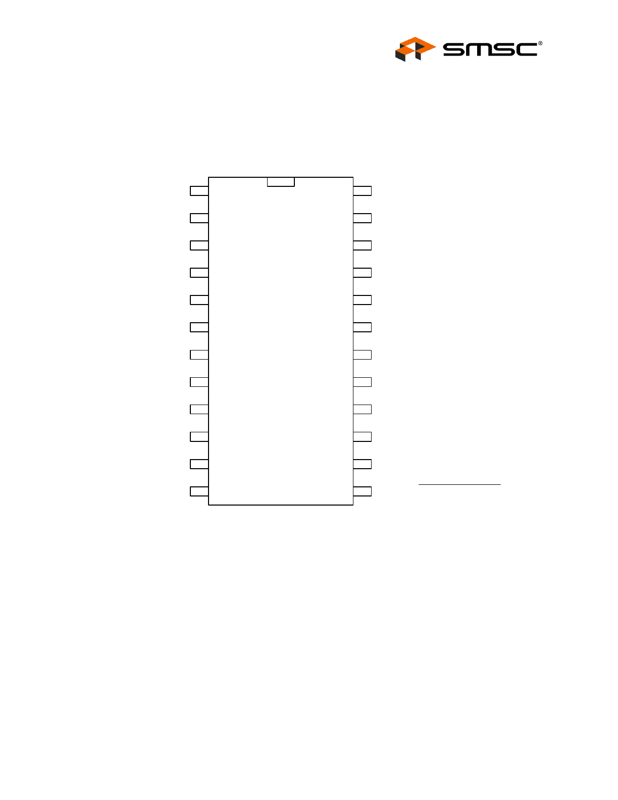
Chapter 2 Pinout
This Environmental Monitoring and Control device (EMC) is offered in a 24 pin SSOP mechanical
package.
The EMC6D102 is a 24 pin SSOP.
Figure 2.1 EMC6D102 Pin Diagram
24
23
22
21
20
19
18
17
16
15
14
13
1
2
3
4
5
6
7
8
9
10
11
12
SDA
SCL
VSS
VCC
VID0
VID1
VID2
VID3
VID4
TACH3/INT#
PWM2/INT#
TACH1
TACH2
PWM1/xTest Out
Vccp
2.5V
12V
5V
Remote1+
Remote1-
Remote2+
Remote2-
TACH4/Address Select
PWM3/Address Enable
EMC6D102
Fan Control Device with Hardware Monitoring and Acoustic Noise Reduction Features
Datasheet
Revision 0.4 (09-25-07)
10
SMSC EMC6D102
DATASHEET
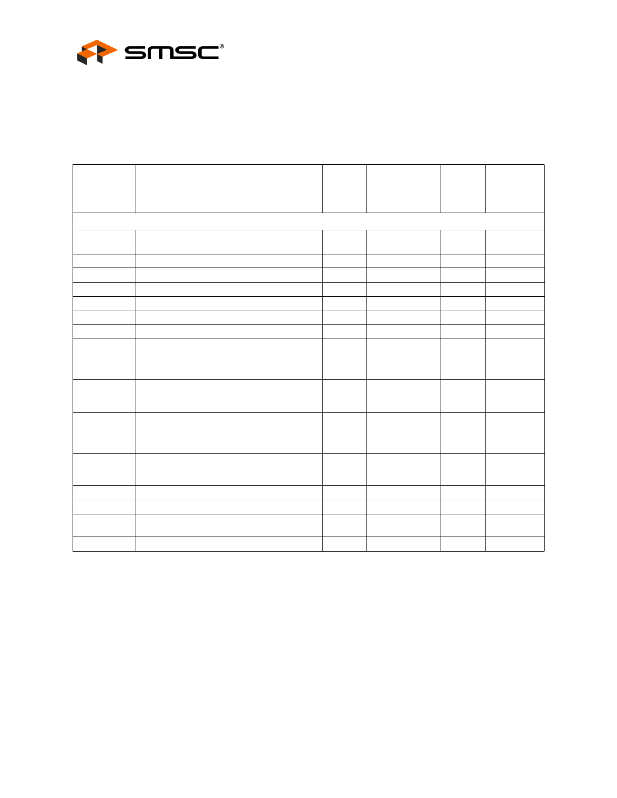
Chapter 3 Pin Description
3.1
Pin Functions
Table 3.1 EMC6D102 Pin Description
NAME
FUNCTION
BUFFER
TYPE
BUFFER
REQUIREMENT
PER FUNCTION
(
Note 3.1
)
POWER
WELL
NOTES
HARDWARE MONITORING BLOCK (24)
SDA
System Management Bus bi-directional Data.
Open Drain output.
I
M
OD3
I
M
OD3
VCC
SCLK
System Management Bus Clock.
I
M
I
M
VCC
VID0
Voltage ID 0 Input
I
M
I
M
VCC
VID1
Voltage ID 1 Input
I
M
I
M
VCC
VID2
Voltage ID 2 Input
I
M
I
M
VCC
VID3
Voltage ID 3 Input
I
M
I
M
VCC
VID4
Voltage ID 4 Input
I
M
I
M
VCC
Remote1-
This is the negative Analog input (current
sink) from the remote thermal diode. This
serves as the negative input into the A/D.
Digital Input.
I
AN
I
AN
VCC
Remote1+
This is the positive input (current source)
from the remote thermal diode. This serves
as the positive input into the A/D.
I
AN
I
AN
VCC
Remote2-
This is the negative Analog input (current
sink) from the remote thermal diode. This
serves as the negative input into the A/D.
Digital Input.
I
AN
I
AN
VCC
Remote2+
This is the positive input (current source)
from the remote thermal diode. This serves
as the positive input into the A/D.
I
AN
I
AN
VCC
+5V_IN
Analog input for +5V
I
AN
I
AN
VCC
Note 3.2
+2.5V_IN
Analog input for +2.5V
I
AN
I
AN
VCC
Note 3.2
Vccp
Analog input for +Vccp (processor voltage: 0
to 3.0V).
I
AN
I
AN
VCC
Note 3.2
12V_IN
Analog input for +12V
I
AN
I
AN
VCC
Note 3.2
SMSC EMC6D102
DATASHEET
Revision 0.4 (09-25-07)
Datasheet
PRODUCT FEATURES
EMC6D102
Fan Control Device with
Hardware Monitoring and
Acoustic Noise Reduction
Features
3.3 Volt Operation (5 Volt Tolerant Input Buffers)
SMBus 2.0 compliant interface (Fixed, Not
Discoverable) With Three Slave Address Options
Fan Control
— PWM (Pulse width Modulation) Outputs (3)
— Fan Tachometer Inputs (4)
— Individual status and enable bits per tach input
— Programmable automatic fan control based on
temperature
— Fan ramp rate control for acoustic noise reduction
Temperature Monitor
— Monitoring of Two Remote Thermal Diodes (+/- 3 deg
C accuracy)
— Internal Ambient Temperature Measurement
— Limit Comparison of all Monitored Values
— Individual status and enable bits per thermal input
— Interrupt Pin for out-of-limit Temperature Indication
— Configurable offset for internal or external temperature
channels.
— Supports 4 programmable temperature averaging
modes
— 2 monitoring modes: Continuous or Cycle (Power
Saving mode)
— Offers 2 Low Power Modes when monitoring is off:
Sleep and Shutdown
Voltage Monitor
— Monitor Power supplies (+2.5V, +5V, +12V, Vccp, and
VCC)
— Individual status and enable bits per voltage input
— Limit Comparison of all Monitored Values
— Interrupt Pin for out-of-limit Voltage Indication
— Supports 4 programmable voltage averaging modes
— 2 monitoring modes: Continuous or Cycle (Power
Saving mode)
— Offers 2 Low Power Modes when monitoring is off:
Sleep and Shutdown
5 VID (Voltage Identification) inputs
XOR Tree test mode
24-pin, SSOP Lead-Free RoHS Compliant package
ORDER NUMBERS:
EMC6D102-CZC FOR 24 PIN SSOP LEAD-FREE ROHS COMPLIANT PACKAGE
EMC6D102-CZC-TR FOR 24 PIN SSOP LEAD-FREE ROHS COMPLIANT PACKAGE
Fan Control Device with Hardware Monitoring and Acoustic Noise Reduction Features
Datasheet
Revision 0.4 (09-25-07)
2
SMSC EMC6D102
DATASHEET
80 ARKAY DRIVE, HAUPPAUGE, NY 11788 (631) 435-6000, FAX (631) 273-3123
Copyright © 2007 SMSC or its subsidiaries. All rights reserved.
Circuit diagrams and other information relating to SMSC products are included as a means of illustrating typical applications. Consequently, complete information sufficient for
construction purposes is not necessarily given. Although the information has been checked and is believed to be accurate, no responsibility is assumed for inaccuracies. SMSC
reserves the right to make changes to specifications and product descriptions at any time without notice. Contact your local SMSC sales office to obtain the latest specifications
before placing your product order. The provision of this information does not convey to the purchaser of the described semiconductor devices any licenses under any patent
rights or other intellectual property rights of SMSC or others. All sales are expressly conditional on your agreement to the terms and conditions of the most recently dated
version of SMSC's standard Terms of Sale Agreement dated before the date of your order (the "Terms of Sale Agreement"). The product may contain design defects or errors
known as anomalies which may cause the product's functions to deviate from published specifications. Anomaly sheets are available upon request. SMSC products are not
designed, intended, authorized or warranted for use in any life support or other application where product failure could cause or contribute to personal injury or severe property
damage. Any and all such uses without prior written approval of an Officer of SMSC and further testing and/or modification will be fully at the risk of the customer. Copies of
this document or other SMSC literature, as well as the Terms of Sale Agreement, may be obtained by visiting SMSC’s website at http://www.smsc.com. SMSC is a registered
trademark of Standard Microsystems Corporation (“SMSC”). Product names and company names are the trademarks of their respective holders.
SMSC DISCLAIMS AND EXCLUDES ANY AND ALL WARRANTIES, INCLUDING WITHOUT LIMITATION ANY AND ALL IMPLIED WARRANTIES OF MERCHANTABILITY,
FITNESS FOR A PARTICULAR PURPOSE, TITLE, AND AGAINST INFRINGEMENT AND THE LIKE, AND ANY AND ALL WARRANTIES ARISING FROM ANY COURSE
OF DEALING OR USAGE OF TRADE. IN NO EVENT SHALL SMSC BE LIABLE FOR ANY DIRECT, INCIDENTAL, INDIRECT, SPECIAL, PUNITIVE, OR CONSEQUENTIAL
DAMAGES; OR FOR LOST DATA, PROFITS, SAVINGS OR REVENUES OF ANY KIND; REGARDLESS OF THE FORM OF ACTION, WHETHER BASED ON CONTRACT;
TORT; NEGLIGENCE OF SMSC OR OTHERS; STRICT LIABILITY; BREACH OF WARRANTY; OR OTHERWISE; WHETHER OR NOT ANY REMEDY OF BUYER IS HELD
TO HAVE FAILED OF ITS ESSENTIAL PURPOSE, AND WHETHER OR NOT SMSC HAS BEEN ADVISED OF THE POSSIBILITY OF SUCH DAMAGES.
Fan Control Device with Hardware Monitoring and Acoustic Noise Reduction Features
Datasheet
SMSC EMC6D102
3
Revision 0.4 (09-25-07)
DATASHEET
Table of Contents
Chapter 1 General Description. . . . . . . . . . . . . . . . . . . . . . . . . . . . . . . . . . . . . . . . . . . . . . . . . 8
Chapter 2 Pinout . . . . . . . . . . . . . . . . . . . . . . . . . . . . . . . . . . . . . . . . . . . . . . . . . . . . . . . . . . . . 9
Chapter 3 Pin Description. . . . . . . . . . . . . . . . . . . . . . . . . . . . . . . . . . . . . . . . . . . . . . . . . . . . 10
3.1
Pin Functions . . . . . . . . . . . . . . . . . . . . . . . . . . . . . . . . . . . . . . . . . . . . . . . . . . . . . . . . . . . . . . . . . 10
3.2
Buffer Type Description . . . . . . . . . . . . . . . . . . . . . . . . . . . . . . . . . . . . . . . . . . . . . . . . . . . . . . . . . 11
3.3
3.3V Operation, 5V Tolerance . . . . . . . . . . . . . . . . . . . . . . . . . . . . . . . . . . . . . . . . . . . . . . . . . . . . 12
Chapter 4 SMBus Interface . . . . . . . . . . . . . . . . . . . . . . . . . . . . . . . . . . . . . . . . . . . . . . . . . . 13
4.1
Slave Address. . . . . . . . . . . . . . . . . . . . . . . . . . . . . . . . . . . . . . . . . . . . . . . . . . . . . . . . . . . . . . . . . 13
4.2
Slave Bus Interface. . . . . . . . . . . . . . . . . . . . . . . . . . . . . . . . . . . . . . . . . . . . . . . . . . . . . . . . . . . . . 14
4.3
Bus Protocols . . . . . . . . . . . . . . . . . . . . . . . . . . . . . . . . . . . . . . . . . . . . . . . . . . . . . . . . . . . . . . . . . 14
4.4
Invalid Protocol Response Behavior. . . . . . . . . . . . . . . . . . . . . . . . . . . . . . . . . . . . . . . . . . . . . . . . 15
4.4.1
Undefined Registers . . . . . . . . . . . . . . . . . . . . . . . . . . . . . . . . . . . . . . . . . . . . . . . . . . . . 15
4.5
General Call Address Response . . . . . . . . . . . . . . . . . . . . . . . . . . . . . . . . . . . . . . . . . . . . . . . . . . 15
4.6
Slave Device Time-Out. . . . . . . . . . . . . . . . . . . . . . . . . . . . . . . . . . . . . . . . . . . . . . . . . . . . . . . . . . 16
4.7
Stretching the SCLK Signal . . . . . . . . . . . . . . . . . . . . . . . . . . . . . . . . . . . . . . . . . . . . . . . . . . . . . . 16
4.8
SMBus Timing . . . . . . . . . . . . . . . . . . . . . . . . . . . . . . . . . . . . . . . . . . . . . . . . . . . . . . . . . . . . . . . . 16
4.9
Bus Reset Sequence . . . . . . . . . . . . . . . . . . . . . . . . . . . . . . . . . . . . . . . . . . . . . . . . . . . . . . . . . . . 16
4.10 SMBus Alert Response Address . . . . . . . . . . . . . . . . . . . . . . . . . . . . . . . . . . . . . . . . . . . . . . . . . . 16
Chapter 5 Hardware Monitoring . . . . . . . . . . . . . . . . . . . . . . . . . . . . . . . . . . . . . . . . . . . . . . 18
5.1
Input Monitoring . . . . . . . . . . . . . . . . . . . . . . . . . . . . . . . . . . . . . . . . . . . . . . . . . . . . . . . . . . . . . . . 18
5.2
Resetting the EMC6D102 . . . . . . . . . . . . . . . . . . . . . . . . . . . . . . . . . . . . . . . . . . . . . . . . . . . . . . . . 18
5.2.1
Power-On Reset . . . . . . . . . . . . . . . . . . . . . . . . . . . . . . . . . . . . . . . . . . . . . . . . . . . . . . . 18
5.2.2
Soft Reset (Initialization) . . . . . . . . . . . . . . . . . . . . . . . . . . . . . . . . . . . . . . . . . . . . . . . . . 18
5.3
Monitoring Modes . . . . . . . . . . . . . . . . . . . . . . . . . . . . . . . . . . . . . . . . . . . . . . . . . . . . . . . . . . . . . . 18
5.3.1
Continuous Monitoring Mode. . . . . . . . . . . . . . . . . . . . . . . . . . . . . . . . . . . . . . . . . . . . . . 19
5.3.2
Cycle Monitoring Mode . . . . . . . . . . . . . . . . . . . . . . . . . . . . . . . . . . . . . . . . . . . . . . . . . . 20
5.4
Interrupt Status Registers . . . . . . . . . . . . . . . . . . . . . . . . . . . . . . . . . . . . . . . . . . . . . . . . . . . . . . . . 21
5.4.1
Diode Fault . . . . . . . . . . . . . . . . . . . . . . . . . . . . . . . . . . . . . . . . . . . . . . . . . . . . . . . . . . . 22
5.5
Interrupt Pin . . . . . . . . . . . . . . . . . . . . . . . . . . . . . . . . . . . . . . . . . . . . . . . . . . . . . . . . . . . . . . . . . . 23
5.6
Low Power Modes . . . . . . . . . . . . . . . . . . . . . . . . . . . . . . . . . . . . . . . . . . . . . . . . . . . . . . . . . . . . . 24
5.6.1
Sleep Mode . . . . . . . . . . . . . . . . . . . . . . . . . . . . . . . . . . . . . . . . . . . . . . . . . . . . . . . . . . . 24
5.6.2
Shutdown Mode. . . . . . . . . . . . . . . . . . . . . . . . . . . . . . . . . . . . . . . . . . . . . . . . . . . . . . . . 24
5.7
Analog Voltage Measurement . . . . . . . . . . . . . . . . . . . . . . . . . . . . . . . . . . . . . . . . . . . . . . . . . . . . 24
5.8
Voltage ID . . . . . . . . . . . . . . . . . . . . . . . . . . . . . . . . . . . . . . . . . . . . . . . . . . . . . . . . . . . . . . . . . . . . 25
5.9
Temperature Measurement . . . . . . . . . . . . . . . . . . . . . . . . . . . . . . . . . . . . . . . . . . . . . . . . . . . . . . 25
5.9.1
Internal Temperature Measurement . . . . . . . . . . . . . . . . . . . . . . . . . . . . . . . . . . . . . . . . 25
5.9.2
External Temperature Measurement . . . . . . . . . . . . . . . . . . . . . . . . . . . . . . . . . . . . . . . . 25
5.9.3
Temperature Data Format . . . . . . . . . . . . . . . . . . . . . . . . . . . . . . . . . . . . . . . . . . . . . . . . 26
5.9.4
Offset Registers. . . . . . . . . . . . . . . . . . . . . . . . . . . . . . . . . . . . . . . . . . . . . . . . . . . . . . . . 27
5.10 Thermal Zones . . . . . . . . . . . . . . . . . . . . . . . . . . . . . . . . . . . . . . . . . . . . . . . . . . . . . . . . . . . . . . . . 27
Chapter 6 Fan Control . . . . . . . . . . . . . . . . . . . . . . . . . . . . . . . . . . . . . . . . . . . . . . . . . . . . . . 28
6.1
General Description . . . . . . . . . . . . . . . . . . . . . . . . . . . . . . . . . . . . . . . . . . . . . . . . . . . . . . . . . . . . 28
6.1.1
Limit and Configuration Registers . . . . . . . . . . . . . . . . . . . . . . . . . . . . . . . . . . . . . . . . . . 28
6.1.2
Device Set-Up . . . . . . . . . . . . . . . . . . . . . . . . . . . . . . . . . . . . . . . . . . . . . . . . . . . . . . . . . 28
6.1.3
PWM Fan Speed Control. . . . . . . . . . . . . . . . . . . . . . . . . . . . . . . . . . . . . . . . . . . . . . . . . 29
6.1.4
Fan Speed Monitoring . . . . . . . . . . . . . . . . . . . . . . . . . . . . . . . . . . . . . . . . . . . . . . . . . . . 37
Fan Control Device with Hardware Monitoring and Acoustic Noise Reduction Features
Datasheet
Revision 0.4 (09-25-07)
4
SMSC EMC6D102
DATASHEET
6.1.5
Linking Fan Tachometers to PWMs. . . . . . . . . . . . . . . . . . . . . . . . . . . . . . . . . . . . . . . . . 43
Chapter 7 Register Set. . . . . . . . . . . . . . . . . . . . . . . . . . . . . . . . . . . . . . . . . . . . . . . . . . . . . . . 45
7.1
Undefined Registers . . . . . . . . . . . . . . . . . . . . . . . . . . . . . . . . . . . . . . . . . . . . . . . . . . . . . . . . . . . . 47
7.2
Defined Registers . . . . . . . . . . . . . . . . . . . . . . . . . . . . . . . . . . . . . . . . . . . . . . . . . . . . . . . . . . . . . . 48
7.2.1
Register 10h: SMSC Test Register . . . . . . . . . . . . . . . . . . . . . . . . . . . . . . . . . . . . . . . . . 48
7.2.2
Register 1Dh, 1Eh, 1Fh: Offset Registers . . . . . . . . . . . . . . . . . . . . . . . . . . . . . . . . . . . . 48
7.2.3
Registers 20-24h: Voltage Reading. . . . . . . . . . . . . . . . . . . . . . . . . . . . . . . . . . . . . . . . . 48
7.2.4
Registers 25-27h: Temperature Reading . . . . . . . . . . . . . . . . . . . . . . . . . . . . . . . . . . . . 49
7.2.5
Registers 28-2Fh: Fan Tachometer Reading . . . . . . . . . . . . . . . . . . . . . . . . . . . . . . . . . 50
7.2.6
Registers 30-32h: Current PWM Duty . . . . . . . . . . . . . . . . . . . . . . . . . . . . . . . . . . . . . . . 51
7.2.7
Register 3Eh: Company ID . . . . . . . . . . . . . . . . . . . . . . . . . . . . . . . . . . . . . . . . . . . . . . . 52
7.2.8
Register 3Fh: Version / Stepping. . . . . . . . . . . . . . . . . . . . . . . . . . . . . . . . . . . . . . . . . . . 52
7.2.9
Register 40h: Ready/Lock/Start Monitoring . . . . . . . . . . . . . . . . . . . . . . . . . . . . . . . . . . . 53
7.2.10
Register 41h: Interrupt Status Register 1 . . . . . . . . . . . . . . . . . . . . . . . . . . . . . . . . . . . . 54
7.2.11
Register 42h: Interrupt Status Register 2 . . . . . . . . . . . . . . . . . . . . . . . . . . . . . . . . . . . . 55
7.2.12
Register 43h: VID . . . . . . . . . . . . . . . . . . . . . . . . . . . . . . . . . . . . . . . . . . . . . . . . . . . . . . 56
7.2.13
Registers 44-4Dh: Voltage Limit Registers . . . . . . . . . . . . . . . . . . . . . . . . . . . . . . . . . . . 57
7.2.14
Registers 4E-53h: Temperature Limit Registers . . . . . . . . . . . . . . . . . . . . . . . . . . . . . . . 57
7.2.15
Registers 54-5Bh: Fan Tachometer Low Limit . . . . . . . . . . . . . . . . . . . . . . . . . . . . . . . . 58
7.2.16
Registers 5C-5Eh: PWM Configuration . . . . . . . . . . . . . . . . . . . . . . . . . . . . . . . . . . . . . . 59
7.2.17
Registers 5F-61h: Zone Temperature Range, PWM Frequency . . . . . . . . . . . . . . . . . . . 60
7.2.18
Register 62h, 63h: Min/Off, PWM Ramp Rate Control . . . . . . . . . . . . . . . . . . . . . . . . . . 62
7.2.19
Registers 64-66h: Minimum PWM Duty Cycle. . . . . . . . . . . . . . . . . . . . . . . . . . . . . . . . . 63
7.2.20
Registers 67-69h: Zone Low Temperature Limit . . . . . . . . . . . . . . . . . . . . . . . . . . . . . . . 64
7.2.21
Registers 6A-6Ch: Absolute Temperature Limit . . . . . . . . . . . . . . . . . . . . . . . . . . . . . . . 65
7.2.22
Registers 6D-6Eh: Zone Hysteresis Registers . . . . . . . . . . . . . . . . . . . . . . . . . . . . . . . . 66
7.2.23
Register 6F: XOR Test Register . . . . . . . . . . . . . . . . . . . . . . . . . . . . . . . . . . . . . . . . . . . 67
7.2.24
Register 79h: SMSC Test Register . . . . . . . . . . . . . . . . . . . . . . . . . . . . . . . . . . . . . . . . . 67
7.2.25
Register 7Ah: SMSC Test Register . . . . . . . . . . . . . . . . . . . . . . . . . . . . . . . . . . . . . . . . . 67
7.2.26
Register 7Bh: SMSC Test Register . . . . . . . . . . . . . . . . . . . . . . . . . . . . . . . . . . . . . . . . . 67
7.2.27
Register 7Ch: Special Function Register. . . . . . . . . . . . . . . . . . . . . . . . . . . . . . . . . . . . . 68
7.2.28
Register 7Eh: Interrupt Enable 1 Register . . . . . . . . . . . . . . . . . . . . . . . . . . . . . . . . . . . . 69
7.2.29
Register 7Fh: Configuration Register . . . . . . . . . . . . . . . . . . . . . . . . . . . . . . . . . . . . . . . 69
7.2.30
Register 80h: Interrupt Enable 2 Register . . . . . . . . . . . . . . . . . . . . . . . . . . . . . . . . . . . . 70
7.2.31
Register 81h: TACH_PWM Association Register . . . . . . . . . . . . . . . . . . . . . . . . . . . . . . 71
7.2.32
Register 82h: Interrupt Enable 3 Register . . . . . . . . . . . . . . . . . . . . . . . . . . . . . . . . . . . . 71
7.2.33
Registers 85h-88h: A/D Converter LSbs Registers . . . . . . . . . . . . . . . . . . . . . . . . . . . . 72
7.2.34
Register 89h: SMSC Test Register . . . . . . . . . . . . . . . . . . . . . . . . . . . . . . . . . . . . . . . . . 73
7.2.35
Registers 8Ah: SMSC Test Register . . . . . . . . . . . . . . . . . . . . . . . . . . . . . . . . . . . . . . . . 73
7.2.36
Registers 8Bh: SMSC Test Register . . . . . . . . . . . . . . . . . . . . . . . . . . . . . . . . . . . . . . . . 73
7.2.37
Registers 8Ch: SMSC Test Register . . . . . . . . . . . . . . . . . . . . . . . . . . . . . . . . . . . . . . . . 73
7.2.38
Registers 8Dh: SMSC Test Register . . . . . . . . . . . . . . . . . . . . . . . . . . . . . . . . . . . . . . . . 73
7.2.39
Registers 8Eh: SMSC Test Register . . . . . . . . . . . . . . . . . . . . . . . . . . . . . . . . . . . . . . . . 73
7.2.40
Registers 90h-93h: TachX Option Registers . . . . . . . . . . . . . . . . . . . . . . . . . . . . . . . . . . 74
7.2.41
Registers 94h-96h: PWMx Option Registers . . . . . . . . . . . . . . . . . . . . . . . . . . . . . . . . . . 75
7.2.42
Register 97h: SMSC Test Register . . . . . . . . . . . . . . . . . . . . . . . . . . . . . . . . . . . . . . . . . 75
7.2.43
Register 98h:SMSC Test Register . . . . . . . . . . . . . . . . . . . . . . . . . . . . . . . . . . . . . . . . . 76
7.2.44
Register FFh: SMSC Test Register . . . . . . . . . . . . . . . . . . . . . . . . . . . . . . . . . . . . . . . . . 76
Chapter 8 Operational Description . . . . . . . . . . . . . . . . . . . . . . . . . . . . . . . . . . . . . . . . . . . . 77
8.1
Maximum Guaranteed Ratings . . . . . . . . . . . . . . . . . . . . . . . . . . . . . . . . . . . . . . . . . . . . . . . . . . . . 77
8.2
Ratings for Operation . . . . . . . . . . . . . . . . . . . . . . . . . . . . . . . . . . . . . . . . . . . . . . . . . . . . . . . . . . . 77
Fan Control Device with Hardware Monitoring and Acoustic Noise Reduction Features
Datasheet
SMSC EMC6D102
5
Revision 0.4 (09-25-07)
DATASHEET
Chapter 9 Timing Diagrams . . . . . . . . . . . . . . . . . . . . . . . . . . . . . . . . . . . . . . . . . . . . . . . . . . 80
9.1
PWM Outputs . . . . . . . . . . . . . . . . . . . . . . . . . . . . . . . . . . . . . . . . . . . . . . . . . . . . . . . . . . . . . . . . . 80
9.2
SMBus Interface . . . . . . . . . . . . . . . . . . . . . . . . . . . . . . . . . . . . . . . . . . . . . . . . . . . . . . . . . . . . . . . 80
Chapter 10 Mechanical Specifications . . . . . . . . . . . . . . . . . . . . . . . . . . . . . . . . . . . . . . . . . . . 82
Appendix A ADC Voltage Conversion . . . . . . . . . . . . . . . . . . . . . . . . . . . . . . . . . . . . . . . . . . . 83
Appendix B Example Fan Circuits . . . . . . . . . . . . . . . . . . . . . . . . . . . . . . . . . . . . . . . . . . . . . . 85
Fan Control Device with Hardware Monitoring and Acoustic Noise Reduction Features
Datasheet
Revision 0.4 (09-25-07)
6
SMSC EMC6D102
DATASHEET
List of Figures
Figure 2.1 EMC6D102 Pin Diagram . . . . . . . . . . . . . . . . . . . . . . . . . . . . . . . . . . . . . . . . . . . . . . . . . . . . . 9
Figure 4.1 Address Selection on EMC6D102 . . . . . . . . . . . . . . . . . . . . . . . . . . . . . . . . . . . . . . . . . . . . . 14
Figure 5.1 Interrupt Control . . . . . . . . . . . . . . . . . . . . . . . . . . . . . . . . . . . . . . . . . . . . . . . . . . . . . . . . . . . 22
Figure 6.1 Automatic Fan Control Flow Diagram . . . . . . . . . . . . . . . . . . . . . . . . . . . . . . . . . . . . . . . . . . 31
Figure 6.2 Automatic Fan Control . . . . . . . . . . . . . . . . . . . . . . . . . . . . . . . . . . . . . . . . . . . . . . . . . . . . . . 33
Figure 6.3 Spin Up Reduction Enabled . . . . . . . . . . . . . . . . . . . . . . . . . . . . . . . . . . . . . . . . . . . . . . . . . . 34
Figure 6.4 Illustration of PWM Ramp Rate Control . . . . . . . . . . . . . . . . . . . . . . . . . . . . . . . . . . . . . . . . . 36
Figure 6.5 PWM and Tachometer Concept. . . . . . . . . . . . . . . . . . . . . . . . . . . . . . . . . . . . . . . . . . . . . . . 39
Figure 7.1 Fan Activity Above Fan Temp Limit . . . . . . . . . . . . . . . . . . . . . . . . . . . . . . . . . . . . . . . . . . . . 61
Figure 9.1 PWMx Output Timing . . . . . . . . . . . . . . . . . . . . . . . . . . . . . . . . . . . . . . . . . . . . . . . . . . . . . . . 80
Figure 9.2 SMBus Timing . . . . . . . . . . . . . . . . . . . . . . . . . . . . . . . . . . . . . . . . . . . . . . . . . . . . . . . . . . . . 80
Figure 10.1 24-Pin SSOP Package Outline, 0.150 Wide Body, 0.025 Pitch . . . . . . . . . . . . . . . . . . . . . . . 82
Figure B.1 Fan Drive Circuitry (Apply to PWM Driving Two Fans) . . . . . . . . . . . . . . . . . . . . . . . . . . . . . 85
Figure B.2 Fan Drive Circuitry (Apply to PWM Driving One Fan) . . . . . . . . . . . . . . . . . . . . . . . . . . . . . . 85
Figure B.3 Fan Tachometer Circuitry (Apply to Each Fan) . . . . . . . . . . . . . . . . . . . . . . . . . . . . . . . . . . . 86
Figure B.4 Remote Diode (Apply to Remote2 Lines). . . . . . . . . . . . . . . . . . . . . . . . . . . . . . . . . . . . . . . . 86
Figure B.5 Suggested Minimum Track Width and Spacing . . . . . . . . . . . . . . . . . . . . . . . . . . . . . . . . . . . 86
Fan Control Device with Hardware Monitoring and Acoustic Noise Reduction Features
Datasheet
SMSC EMC6D102
7
Revision 0.4 (09-25-07)
DATASHEET
List of Tables
Table 3.1 EMC6D102 Pin Description . . . . . . . . . . . . . . . . . . . . . . . . . . . . . . . . . . . . . . . . . . . . . . . . . . . 10
Table 3.2 Buffer Type Descriptions . . . . . . . . . . . . . . . . . . . . . . . . . . . . . . . . . . . . . . . . . . . . . . . . . . . . . 11
Table 4.1 SMBus Slave Address Options . . . . . . . . . . . . . . . . . . . . . . . . . . . . . . . . . . . . . . . . . . . . . . . . 13
Table 4.2 SMBus Write Byte Protocol . . . . . . . . . . . . . . . . . . . . . . . . . . . . . . . . . . . . . . . . . . . . . . . . . . . 15
Table 4.3 SMBus Read Byte Protocol . . . . . . . . . . . . . . . . . . . . . . . . . . . . . . . . . . . . . . . . . . . . . . . . . . . 15
Table 4.4 Modified SMBus Receive Byte Protocol Response to ARA. . . . . . . . . . . . . . . . . . . . . . . . . . . 16
Table 5.1 AVG[2:0] Bit Decoder . . . . . . . . . . . . . . . . . . . . . . . . . . . . . . . . . . . . . . . . . . . . . . . . . . . . . . . 19
Table 5.2 Conversion Cycle Timing. . . . . . . . . . . . . . . . . . . . . . . . . . . . . . . . . . . . . . . . . . . . . . . . . . . . . 19
Table 5.3 ADC Conversion Sequence. . . . . . . . . . . . . . . . . . . . . . . . . . . . . . . . . . . . . . . . . . . . . . . . . . . 20
Table 5.4 Low Power Mode Control Bits . . . . . . . . . . . . . . . . . . . . . . . . . . . . . . . . . . . . . . . . . . . . . . . . . 24
Table 5.5 Min/Max ADC Conversion Table . . . . . . . . . . . . . . . . . . . . . . . . . . . . . . . . . . . . . . . . . . . . . . . 25
Table 5.6 Temperature Data Format . . . . . . . . . . . . . . . . . . . . . . . . . . . . . . . . . . . . . . . . . . . . . . . . . . . . 26
Table 6.1 PWM Ramp Rate. . . . . . . . . . . . . . . . . . . . . . . . . . . . . . . . . . . . . . . . . . . . . . . . . . . . . . . . . . . 35
Table 6.2 Max Tachometer Count Values for Different Stretch Periods . . . . . . . . . . . . . . . . . . . . . . . . . 41
Table 6.3 Minimum RPM Detectable Using 3 Edges – No PWM Stretching . . . . . . . . . . . . . . . . . . . . . . 41
Table 6.4 Minimum RPM Detectable Using 2 Edges – No PWM Stretching . . . . . . . . . . . . . . . . . . . . . . 42
Table 6.5 Minimum RPM Detectable– With PWM Stretching . . . . . . . . . . . . . . . . . . . . . . . . . . . . . . . . . 43
Table 7.1 Register Summary . . . . . . . . . . . . . . . . . . . . . . . . . . . . . . . . . . . . . . . . . . . . . . . . . . . . . . . . . . 45
Table 7.2 Voltage vs. Register Reading . . . . . . . . . . . . . . . . . . . . . . . . . . . . . . . . . . . . . . . . . . . . . . . . . 49
Table 7.3 Temperature vs. Register Reading . . . . . . . . . . . . . . . . . . . . . . . . . . . . . . . . . . . . . . . . . . . . . 50
Table 7.4 PWM Duty vs Register Reading . . . . . . . . . . . . . . . . . . . . . . . . . . . . . . . . . . . . . . . . . . . . . . . 52
Table 7.6 Temperature Limits vs. Register Settings . . . . . . . . . . . . . . . . . . . . . . . . . . . . . . . . . . . . . . . . 58
Table 7.7 Fan Zone Setting . . . . . . . . . . . . . . . . . . . . . . . . . . . . . . . . . . . . . . . . . . . . . . . . . . . . . . . . . . . 59
Table 7.8 Fan Spin-Up Register . . . . . . . . . . . . . . . . . . . . . . . . . . . . . . . . . . . . . . . . . . . . . . . . . . . . . . . 60
Table 7.9 Register Setting vs. PWM Frequency . . . . . . . . . . . . . . . . . . . . . . . . . . . . . . . . . . . . . . . . . . . 61
Table 7.10 Register Setting vs. Temperature Range . . . . . . . . . . . . . . . . . . . . . . . . . . . . . . . . . . . . . . . . 62
Table 7.11 PWM output below Limit depending on value of Off/Min . . . . . . . . . . . . . . . . . . . . . . . . . . . . . 62
Table 7.12 PWM Ramp Rate Control . . . . . . . . . . . . . . . . . . . . . . . . . . . . . . . . . . . . . . . . . . . . . . . . . . . . 63
Table 7.13 PWM Duty vs. Register Setting . . . . . . . . . . . . . . . . . . . . . . . . . . . . . . . . . . . . . . . . . . . . . . . . 64
Table 7.14 Temperature Limit vs. Register Setting . . . . . . . . . . . . . . . . . . . . . . . . . . . . . . . . . . . . . . . . . . 65
Table 7.15 Absolute Limit vs. Register Setting . . . . . . . . . . . . . . . . . . . . . . . . . . . . . . . . . . . . . . . . . . . . . 66
Table 7.16 Hysteresis Settings . . . . . . . . . . . . . . . . . . . . . . . . . . . . . . . . . . . . . . . . . . . . . . . . . . . . . . . . . 66
Table 7.17 AVG[2:0] Bit Decoder . . . . . . . . . . . . . . . . . . . . . . . . . . . . . . . . . . . . . . . . . . . . . . . . . . . . . . . 68
Table 9.1 Timing for PWM[1:3] Outputs . . . . . . . . . . . . . . . . . . . . . . . . . . . . . . . . . . . . . . . . . . . . . . . . . 80
Table 10.1 24-pin SSOP Package Parameters . . . . . . . . . . . . . . . . . . . . . . . . . . . . . . . . . . . . . . . . . . . . . 82
Table A.1 Analog-to-Digital Voltage Conversions for Hardware Monitoring Block. . . . . . . . . . . . . . . . . . 83
Fan Control Device with Hardware Monitoring and Acoustic Noise Reduction Features
Datasheet
Revision 0.4 (09-25-07)
8
SMSC EMC6D102
DATASHEET
Chapter 1 General Description
The EMC6D102 is an environmental monitoring device with automatic fan control capability. This ACPI
compliant device provides hardware monitoring for up to five voltages and three thermal zones,
measures the speed of up to four fans, and controls the speed of multiple DC fans using Pulse Width
Modulator (PWM) outputs.
The EMC6D102 hardware monitor provides analog inputs for monitoring external voltages of +2.5V,
+5V, +12V and Vccp. This device has the capability to monitor its own internal VCC power supply,
which may be connected to either main power (VCC) or the suspend power well (VTR). In addition to
monitoring the processor voltage, VID inputs are available to identify the voltage specification. External
components are not required for voltage scaling or similar treatment.
The EMC6D102 hardware monitor includes support for monitoring three thermal zones: two external
and one internal. The external temperatures are measured via thermal diode inputs capable of
monitoring remote devices. In addition, they are equipped with an ambient temperature sensor for
measuring the internal temperature.
Pulse Width Modulators (PWM) control the speed of the fans by varying the output duty cycle of the
PWM. Each PWM can be associated with any or all of the thermal zones monitored. As the
temperature of the associated zone varies, the PWM duty cycle is adjusted accordingly. The Ramp
Rate Control feature controls the rate of change of the PWM output, thereby reducing system noise
created by changing the fan speed. The speed of each fan is monitored by a Fan Tachometer input.
The measured values are compared to values stored in Limit Registers to detect if a fan has stalled
or seized.
Fan speed may be under host software control or automatic. In host control mode, the host software
continuously monitors temperature and fan speed registers, makes decisions as to desired fan speed
and sets the PWM’s to drive the required fan speed. This device offers an interrupt output signal
(INT#), which may be used to interrupt the host on out-of-limit temperature or voltage condition
enabling an ACPI response as opposed to the host software continuously monitoring status. In auto
“zone” mode, the logic continuously monitors the temperature and fan speeds and adjusts speeds
without intervention from the host CPU. Fan speed is adjusted according to an algorithm using the
temperature measured in the selected zone, the high and low limits set by the user, and the current
fan speed.
Fan Control Device with Hardware Monitoring and Acoustic Noise Reduction Features
Datasheet
SMSC EMC6D102
9
Revision 0.4 (09-25-07)
DATASHEET
Chapter 2 Pinout
This Environmental Monitoring and Control device (EMC) is offered in a 24 pin SSOP mechanical
package.
The EMC6D102 is a 24 pin SSOP.
Figure 2.1 EMC6D102 Pin Diagram
24
23
22
21
20
19
18
17
16
15
14
13
1
2
3
4
5
6
7
8
9
10
11
12
SDA
SCL
VSS
VCC
VID0
VID1
VID2
VID3
VID4
TACH3/INT#
PWM2/INT#
TACH1
TACH2
PWM1/xTest Out
Vccp
2.5V
12V
5V
Remote1+
Remote1-
Remote2+
Remote2-
TACH4/Address Select
PWM3/Address Enable
EMC6D102
Fan Control Device with Hardware Monitoring and Acoustic Noise Reduction Features
Datasheet
Revision 0.4 (09-25-07)
10
SMSC EMC6D102
DATASHEET
Chapter 3 Pin Description
3.1
Pin Functions
Table 3.1 EMC6D102 Pin Description
NAME
FUNCTION
BUFFER
TYPE
BUFFER
REQUIREMENT
PER FUNCTION
(
Note 3.1
)
POWER
WELL
NOTES
HARDWARE MONITORING BLOCK (24)
SDA
System Management Bus bi-directional Data.
Open Drain output.
I
M
OD3
I
M
OD3
VCC
SCLK
System Management Bus Clock.
I
M
I
M
VCC
VID0
Voltage ID 0 Input
I
M
I
M
VCC
VID1
Voltage ID 1 Input
I
M
I
M
VCC
VID2
Voltage ID 2 Input
I
M
I
M
VCC
VID3
Voltage ID 3 Input
I
M
I
M
VCC
VID4
Voltage ID 4 Input
I
M
I
M
VCC
Remote1-
This is the negative Analog input (current
sink) from the remote thermal diode. This
serves as the negative input into the A/D.
Digital Input.
I
AN
I
AN
VCC
Remote1+
This is the positive input (current source)
from the remote thermal diode. This serves
as the positive input into the A/D.
I
AN
I
AN
VCC
Remote2-
This is the negative Analog input (current
sink) from the remote thermal diode. This
serves as the negative input into the A/D.
Digital Input.
I
AN
I
AN
VCC
Remote2+
This is the positive input (current source)
from the remote thermal diode. This serves
as the positive input into the A/D.
I
AN
I
AN
VCC
+5V_IN
Analog input for +5V
I
AN
I
AN
VCC
Note 3.2
+2.5V_IN
Analog input for +2.5V
I
AN
I
AN
VCC
Note 3.2
Vccp
Analog input for +Vccp (processor voltage: 0
to 3.0V).
I
AN
I
AN
VCC
Note 3.2
12V_IN
Analog input for +12V
I
AN
I
AN
VCC
Note 3.2