

SMSC EMC2102
DATASHEET
Revision 2.02 (05-17-07)
Datasheet
PRODUCT FEATURES
EMC2102
RPM-Based Fan
Controller with HW
Thermal Shutdown
General Description
The EMC2102 is an SMBus, closed-loop, RPM-based
fan controller/driver with hardware (HW) thermal
shutdown and reset controller. The EMC2102 is
packaged in a thermally enhanced, compact, 5x5, 28-
pin lead-free RoHS compliant QFN package.
The EMC2102 utilizes Beta Compensation (an
implementation of the BJT or transistor model for
thermal diodes) and Resistance Error Correction (REC)
to accurately monitor three external temperature zones.
These features allow great accuracy for CPU substrate
thermal diodes on multiple process geometries as well
as with discrete diode-connected transistors. Both Beta
Compensation and REC can be disabled on the
EMC2102 to maintain accuracy when monitoring AMD
thermal diodes.
The EMC2102 includes a closed-loop RPM based Fan
Control Algorithm that integrates a linear fan driver
capable of sourcing 600mA of current. The fan control
algorithm is designed to work with fans that operate up
to 16,000 RPMs.
The EMC2102 provides a stand-alone HW thermal
shutdown block. The HW thermal shutdown logic can be
configured for a few common configurations based on
the strapping level of the SHDN_SEL pin on the PCB.
The HW thermal shutdown point can be set in 1°C
increments by using a discrete resistor divider
implemented on the TRIP_SET pin.
The EMC2102 also provides 5V supply ‘power good’
function with a threshold of 4.5V. This function is
provided on the RESET# pin.
Features
Designed to support 45nm, 65nm, and 90nm CPU
Diodes
Supports BJT and transistor models for diode
channels
Closed-Loop RPM Based Fan Controller
—
Accepts External Clock Source To Achieve 2%
Accuracy
Integrated Linear Fan Driver
—
600mA Drive Capability
HW Thermal Shutdown (SYS_SHDN#)
—
1
°C Incremental Set Points For Thermal Shutdown
—
Cannot be disabled by software
Provides Reset Function (RESET#) On 5V Supply
Three Remote Thermal Zones
—
±1°C Accuracy (60°C to 100°C)
—
1
°C Resolution
Resistance Error Correction On Thermal Diode
Channels
—
Eliminates Temperature Offset Due To Series
Resistance From PCB Traces And Thermal ‘Diode’
Thermally Enhanced, 28-pin, 5x5 QFN Lead-free
RoHS Compliant Package
Operates From Single 3.0 - 3.6V Supply
—
5V Supply For Linear Fan Driver
Software Configurable ALERT# Signal For Diode
Fault, Fan Stall Or System Warning
Applications
Notebook Computers
Desktop Computers
Embedded Applications

ORDER NUMBER:
EMC2102-DZK FOR 28-PIN QFN LEAD-FREE ROHS COMPLIANT PACKAGE (ADDRESS - 011_1101)
RPM-Based Fan Controller with HW Thermal Shutdown
Datasheet
Revision 2.02 (05-17-07)
2
SMSC EMC2102
DATASHEET
80 ARKAY DRIVE, HAUPPAUGE, NY 11788 (631) 435-6000, FAX (631) 273-3123
Copyright © 2007 SMSC or its subsidiaries. All rights reserved.
Circuit diagrams and other information relating to SMSC products are included as a means of illustrating typical applications. Consequently, complete information sufficient for
construction purposes is not necessarily given. Although the information has been checked and is believed to be accurate, no responsibility is assumed for inaccuracies. SMSC
reserves the right to make changes to specifications and product descriptions at any time without notice. Contact your local SMSC sales office to obtain the latest specifications
before placing your product order. The provision of this information does not convey to the purchaser of the described semiconductor devices any licenses under any patent
rights or other intellectual property rights of SMSC or others. All sales are expressly conditional on your agreement to the terms and conditions of the most recently dated
version of SMSC's standard Terms of Sale Agreement dated before the date of your order (the "Terms of Sale Agreement"). The product may contain design defects or errors
known as anomalies which may cause the product's functions to deviate from published specifications. Anomaly sheets are available upon request. SMSC products are not
designed, intended, authorized or warranted for use in any life support or other application where product failure could cause or contribute to personal injury or severe property
damage. Any and all such uses without prior written approval of an Officer of SMSC and further testing and/or modification will be fully at the risk of the customer. Copies of
this document or other SMSC literature, as well as the Terms of Sale Agreement, may be obtained by visiting SMSC’s website at http://www.smsc.com. SMSC is a registered
trademark of Standard Microsystems Corporation (“SMSC”). Product names and company names are the trademarks of their respective holders.
SMSC DISCLAIMS AND EXCLUDES ANY AND ALL WARRANTIES, INCLUDING WITHOUT LIMITATION ANY AND ALL IMPLIED WARRANTIES OF MERCHANTABILITY,
FITNESS FOR A PARTICULAR PURPOSE, TITLE, AND AGAINST INFRINGEMENT AND THE LIKE, AND ANY AND ALL WARRANTIES ARISING FROM ANY COURSE
OF DEALING OR USAGE OF TRADE. IN NO EVENT SHALL SMSC BE LIABLE FOR ANY DIRECT, INCIDENTAL, INDIRECT, SPECIAL, PUNITIVE, OR CONSEQUENTIAL
DAMAGES; OR FOR LOST DATA, PROFITS, SAVINGS OR REVENUES OF ANY KIND; REGARDLESS OF THE FORM OF ACTION, WHETHER BASED ON CONTRACT;
TORT; NEGLIGENCE OF SMSC OR OTHERS; STRICT LIABILITY; BREACH OF WARRANTY; OR OTHERWISE; WHETHER OR NOT ANY REMEDY OF BUYER IS HELD
TO HAVE FAILED OF ITS ESSENTIAL PURPOSE, AND WHETHER OR NOT SMSC HAS BEEN ADVISED OF THE POSSIBILITY OF SUCH DAMAGES.

RPM-Based Fan Controller with HW Thermal Shutdown
Datasheet
SMSC EMC2102
3
Revision 2.02 (05-17-07)
DATASHEET
Table of Contents
Chapter 1
Block Diagram . . . . . . . . . . . . . . . . . . . . . . . . . . . . . . . . . . . . . . . . . . . . . . . . . . . . . 7
Chapter 2
Pinout . . . . . . . . . . . . . . . . . . . . . . . . . . . . . . . . . . . . . . . . . . . . . . . . . . . . . . . . . . . . 8
2.1
Pin Layout for EMC2102. . . . . . . . . . . . . . . . . . . . . . . . . . . . . . . . . . . . . . . . . . . . . . . . . . . . . . . . . . 8
2.2
Pin Description for EMC2102 . . . . . . . . . . . . . . . . . . . . . . . . . . . . . . . . . . . . . . . . . . . . . . . . . . . . . . 9
Chapter 3
Electrical Specifications . . . . . . . . . . . . . . . . . . . . . . . . . . . . . . . . . . . . . . . . . . . . 11
3.1
Absolute Maximum Ratings . . . . . . . . . . . . . . . . . . . . . . . . . . . . . . . . . . . . . . . . . . . . . . . . . . . . . . 11
3.2
Electrical Specifications . . . . . . . . . . . . . . . . . . . . . . . . . . . . . . . . . . . . . . . . . . . . . . . . . . . . . . . . . 11
3.3
SMBus Electrical Specifications . . . . . . . . . . . . . . . . . . . . . . . . . . . . . . . . . . . . . . . . . . . . . . . . . . . 13
Chapter 4
System Management Bus Interface Protocol . . . . . . . . . . . . . . . . . . . . . . . . . . . 15
4.1
Write Byte . . . . . . . . . . . . . . . . . . . . . . . . . . . . . . . . . . . . . . . . . . . . . . . . . . . . . . . . . . . . . . . . . . . . 15
4.2
Read Byte . . . . . . . . . . . . . . . . . . . . . . . . . . . . . . . . . . . . . . . . . . . . . . . . . . . . . . . . . . . . . . . . . . . . 16
4.3
Send Byte . . . . . . . . . . . . . . . . . . . . . . . . . . . . . . . . . . . . . . . . . . . . . . . . . . . . . . . . . . . . . . . . . . . . 16
4.4
Receive Byte. . . . . . . . . . . . . . . . . . . . . . . . . . . . . . . . . . . . . . . . . . . . . . . . . . . . . . . . . . . . . . . . . . 16
4.5
Alert Response Address . . . . . . . . . . . . . . . . . . . . . . . . . . . . . . . . . . . . . . . . . . . . . . . . . . . . . . . . . 16
4.6
SMBus Address . . . . . . . . . . . . . . . . . . . . . . . . . . . . . . . . . . . . . . . . . . . . . . . . . . . . . . . . . . . . . . . 17
4.7
SMBus Time-out . . . . . . . . . . . . . . . . . . . . . . . . . . . . . . . . . . . . . . . . . . . . . . . . . . . . . . . . . . . . . . . 17
Chapter 5
General Description . . . . . . . . . . . . . . . . . . . . . . . . . . . . . . . . . . . . . . . . . . . . . . . . 18
5.1
Temperature Monitoring . . . . . . . . . . . . . . . . . . . . . . . . . . . . . . . . . . . . . . . . . . . . . . . . . . . . . . . . . 20
5.1.1
Resistance Error Correction . . . . . . . . . . . . . . . . . . . . . . . . . . . . . . . . . . . . . . . . . . . . . . 20
5.1.2
Beta Compensation . . . . . . . . . . . . . . . . . . . . . . . . . . . . . . . . . . . . . . . . . . . . . . . . . . . . . 20
5.1.3
Fault Queue . . . . . . . . . . . . . . . . . . . . . . . . . . . . . . . . . . . . . . . . . . . . . . . . . . . . . . . . . . . 20
5.2
Fan Control Modes of Operation . . . . . . . . . . . . . . . . . . . . . . . . . . . . . . . . . . . . . . . . . . . . . . . . . . 21
5.3
RPM based Fan Control Algorithm . . . . . . . . . . . . . . . . . . . . . . . . . . . . . . . . . . . . . . . . . . . . . . . . . 21
5.3.1
Programming the RPM based Fan Control Algorithm . . . . . . . . . . . . . . . . . . . . . . . . . . . 23
5.3.2
TACH Measurement . . . . . . . . . . . . . . . . . . . . . . . . . . . . . . . . . . . . . . . . . . . . . . . . . . . . 23
5.3.2.1 Stalled Fan23
5.3.3
Spin Up Routine . . . . . . . . . . . . . . . . . . . . . . . . . . . . . . . . . . . . . . . . . . . . . . . . . . . . . . . 23
5.3.4
FAN_MODE Pin . . . . . . . . . . . . . . . . . . . . . . . . . . . . . . . . . . . . . . . . . . . . . . . . . . . . . . . 25
5.3.5
32.768KHz Clock Source . . . . . . . . . . . . . . . . . . . . . . . . . . . . . . . . . . . . . . . . . . . . . . . . 25
5.4
Watchdog Timer . . . . . . . . . . . . . . . . . . . . . . . . . . . . . . . . . . . . . . . . . . . . . . . . . . . . . . . . . . . . . . . 25
5.5
High Side Fan Driver . . . . . . . . . . . . . . . . . . . . . . . . . . . . . . . . . . . . . . . . . . . . . . . . . . . . . . . . . . . 26
5.5.1
Overcurrent Limit . . . . . . . . . . . . . . . . . . . . . . . . . . . . . . . . . . . . . . . . . . . . . . . . . . . . . . . 26
5.6
Internal Thermal Shutdown (TSD) . . . . . . . . . . . . . . . . . . . . . . . . . . . . . . . . . . . . . . . . . . . . . . . . . 26
5.7
Critical/Thermal Shutdown . . . . . . . . . . . . . . . . . . . . . . . . . . . . . . . . . . . . . . . . . . . . . . . . . . . . . . . 26
5.7.1
TRIP_SET . . . . . . . . . . . . . . . . . . . . . . . . . . . . . . . . . . . . . . . . . . . . . . . . . . . . . . . . . . . . 28
5.7.2
SHDN_SEL Pin . . . . . . . . . . . . . . . . . . . . . . . . . . . . . . . . . . . . . . . . . . . . . . . . . . . . . . . . 28
5.7.3
Internal HW_SHDN Signal . . . . . . . . . . . . . . . . . . . . . . . . . . . . . . . . . . . . . . . . . . . . . . . 29
5.8
5V Reset Controller . . . . . . . . . . . . . . . . . . . . . . . . . . . . . . . . . . . . . . . . . . . . . . . . . . . . . . . . . . . . 30
Chapter 6
Register Set . . . . . . . . . . . . . . . . . . . . . . . . . . . . . . . . . . . . . . . . . . . . . . . . . . . . . . . 31
6.1
Register Map . . . . . . . . . . . . . . . . . . . . . . . . . . . . . . . . . . . . . . . . . . . . . . . . . . . . . . . . . . . . . . . . . 31
6.1.1
Lock Entries . . . . . . . . . . . . . . . . . . . . . . . . . . . . . . . . . . . . . . . . . . . . . . . . . . . . . . . . . . . 32
6.2
Temperature Data Registers . . . . . . . . . . . . . . . . . . . . . . . . . . . . . . . . . . . . . . . . . . . . . . . . . . . . . 33
6.3
Critical/Thermal Shutdown Temperature Register . . . . . . . . . . . . . . . . . . . . . . . . . . . . . . . . . . . . . 34
6.4
Configuration Register . . . . . . . . . . . . . . . . . . . . . . . . . . . . . . . . . . . . . . . . . . . . . . . . . . . . . . . . . . 34
6.5
Conversion Rate Register. . . . . . . . . . . . . . . . . . . . . . . . . . . . . . . . . . . . . . . . . . . . . . . . . . . . . . . . 35
6.6
Interrupt Status Register 1 . . . . . . . . . . . . . . . . . . . . . . . . . . . . . . . . . . . . . . . . . . . . . . . . . . . . . . . 36

RPM-Based Fan Controller with HW Thermal Shutdown
Datasheet
Revision 2.02 (05-17-07)
4
SMSC EMC2102
DATASHEET
6.7
Interrupt Status Register 2 . . . . . . . . . . . . . . . . . . . . . . . . . . . . . . . . . . . . . . . . . . . . . . . . . . . . . . . 37
6.8
Interrupt Mask Register . . . . . . . . . . . . . . . . . . . . . . . . . . . . . . . . . . . . . . . . . . . . . . . . . . . . . . . . . 37
6.9
Beta Configuration Registers . . . . . . . . . . . . . . . . . . . . . . . . . . . . . . . . . . . . . . . . . . . . . . . . . . . . . 38
6.10
REC Configuration Register . . . . . . . . . . . . . . . . . . . . . . . . . . . . . . . . . . . . . . . . . . . . . . . . . . . . . . 39
6.11
Temperature Limit Registers . . . . . . . . . . . . . . . . . . . . . . . . . . . . . . . . . . . . . . . . . . . . . . . . . . . . . 40
6.12
Fan Driver Setting Register . . . . . . . . . . . . . . . . . . . . . . . . . . . . . . . . . . . . . . . . . . . . . . . . . . . . . . 40
6.13
Fan Configuration Register. . . . . . . . . . . . . . . . . . . . . . . . . . . . . . . . . . . . . . . . . . . . . . . . . . . . . . . 41
6.14
Fan Spin Up Configuration Register . . . . . . . . . . . . . . . . . . . . . . . . . . . . . . . . . . . . . . . . . . . . . . . . 42
6.15
Fan Step Register. . . . . . . . . . . . . . . . . . . . . . . . . . . . . . . . . . . . . . . . . . . . . . . . . . . . . . . . . . . . . . 43
6.16
Fan Minimum Drive Register . . . . . . . . . . . . . . . . . . . . . . . . . . . . . . . . . . . . . . . . . . . . . . . . . . . . . 43
6.17
Valid TACH Count Register . . . . . . . . . . . . . . . . . . . . . . . . . . . . . . . . . . . . . . . . . . . . . . . . . . . . . . 44
6.18
TACH Target Register . . . . . . . . . . . . . . . . . . . . . . . . . . . . . . . . . . . . . . . . . . . . . . . . . . . . . . . . . . 44
6.19
TACH Reading Register . . . . . . . . . . . . . . . . . . . . . . . . . . . . . . . . . . . . . . . . . . . . . . . . . . . . . . . . . 44
6.20
Product ID Register . . . . . . . . . . . . . . . . . . . . . . . . . . . . . . . . . . . . . . . . . . . . . . . . . . . . . . . . . . . . 45
6.21
Revision Register . . . . . . . . . . . . . . . . . . . . . . . . . . . . . . . . . . . . . . . . . . . . . . . . . . . . . . . . . . . . . . 46
Chapter 7
Package Drawing . . . . . . . . . . . . . . . . . . . . . . . . . . . . . . . . . . . . . . . . . . . . . . . . . . 47
Appendix A TACH Reading Table - 2000 RPM Range. . . . . . . . . . . . . . . . . . . . . . . . . . . . . . 48
Appendix B TACH Reading Table - 500RPM Range . . . . . . . . . . . . . . . . . . . . . . . . . . . . . . . 51

RPM-Based Fan Controller with HW Thermal Shutdown
Datasheet
SMSC EMC2102
5
Revision 2.02 (05-17-07)
DATASHEET
List of Figures
Figure 1.1 EMC2102 Block Diagram. . . . . . . . . . . . . . . . . . . . . . . . . . . . . . . . . . . . . . . . . . . . . . . . . . . . . 7
Figure 2.1 EMC2102 Pin Diagram . . . . . . . . . . . . . . . . . . . . . . . . . . . . . . . . . . . . . . . . . . . . . . . . . . . . . . 8
Figure 4.1 SMBus Timing Diagram . . . . . . . . . . . . . . . . . . . . . . . . . . . . . . . . . . . . . . . . . . . . . . . . . . . . . 15
Figure 5.1 EMC2102 System Diagram . . . . . . . . . . . . . . . . . . . . . . . . . . . . . . . . . . . . . . . . . . . . . . . . . . 19
Figure 5.2 RPM based Fan Control Algorithm . . . . . . . . . . . . . . . . . . . . . . . . . . . . . . . . . . . . . . . . . . . . 22
Figure 5.3 Spin Up Routine . . . . . . . . . . . . . . . . . . . . . . . . . . . . . . . . . . . . . . . . . . . . . . . . . . . . . . . . . . . 24
Figure 5.4 EMC2102 Critical/Thermal Shutdown Block Diagram . . . . . . . . . . . . . . . . . . . . . . . . . . . . . . 27
Figure 5.5 HW_SHDN Operation . . . . . . . . . . . . . . . . . . . . . . . . . . . . . . . . . . . . . . . . . . . . . . . . . . . . . . 29
Figure 5.6 5V Reset Controller Timing . . . . . . . . . . . . . . . . . . . . . . . . . . . . . . . . . . . . . . . . . . . . . . . . . . 30
Figure 7.1 EMC2102 28-Pin 5x5mm QFN Package Outline and Parameters . . . . . . . . . . . . . . . . . . . . 47

RPM-Based Fan Controller with HW Thermal Shutdown
Datasheet
Revision 2.02 (05-17-07)
6
SMSC EMC2102
DATASHEET
List of Tables
Table 2.1 Pin Description. . . . . . . . . . . . . . . . . . . . . . . . . . . . . . . . . . . . . . . . . . . . . . . . . . . . . . . . . . . . . . 9
Table 3.1 Absolute Maximum Ratings . . . . . . . . . . . . . . . . . . . . . . . . . . . . . . . . . . . . . . . . . . . . . . . . . . . 11
Table 3.2 Electrical Specifications . . . . . . . . . . . . . . . . . . . . . . . . . . . . . . . . . . . . . . . . . . . . . . . . . . . . . . 11
Table 3.3 SMBus Electrical Specifications . . . . . . . . . . . . . . . . . . . . . . . . . . . . . . . . . . . . . . . . . . . . . . . 13
Table 4.1 Protocol Format . . . . . . . . . . . . . . . . . . . . . . . . . . . . . . . . . . . . . . . . . . . . . . . . . . . . . . . . . . . . 15
Table 4.2 Write Byte Protocol . . . . . . . . . . . . . . . . . . . . . . . . . . . . . . . . . . . . . . . . . . . . . . . . . . . . . . . . . 15
Table 4.3 Read Byte Protocol . . . . . . . . . . . . . . . . . . . . . . . . . . . . . . . . . . . . . . . . . . . . . . . . . . . . . . . . . 16
Table 4.4 Send Byte Protocol . . . . . . . . . . . . . . . . . . . . . . . . . . . . . . . . . . . . . . . . . . . . . . . . . . . . . . . . . 16
Table 4.5 Receive Byte Protocol . . . . . . . . . . . . . . . . . . . . . . . . . . . . . . . . . . . . . . . . . . . . . . . . . . . . . . . 16
Table 4.6 Alert Response Address Protocol . . . . . . . . . . . . . . . . . . . . . . . . . . . . . . . . . . . . . . . . . . . . . . 16
Table 5.1 Fan Controls Active for Operating Mode . . . . . . . . . . . . . . . . . . . . . . . . . . . . . . . . . . . . . . . . . 21
Table 5.2 FAN_MODE Pin Functions . . . . . . . . . . . . . . . . . . . . . . . . . . . . . . . . . . . . . . . . . . . . . . . . . . . 25
Table 5.3 CLK_SEL Pin Functions . . . . . . . . . . . . . . . . . . . . . . . . . . . . . . . . . . . . . . . . . . . . . . . . . . . . . 25
Table 5.4 SHDN_SEL Pin Configuration . . . . . . . . . . . . . . . . . . . . . . . . . . . . . . . . . . . . . . . . . . . . . . . . . 28
Table 6.1 EMC2102 Register Set . . . . . . . . . . . . . . . . . . . . . . . . . . . . . . . . . . . . . . . . . . . . . . . . . . . . . . 31
Table 6.2 Temperature data Registers . . . . . . . . . . . . . . . . . . . . . . . . . . . . . . . . . . . . . . . . . . . . . . . . . . 33
Table 6.3 Temperature Data Format . . . . . . . . . . . . . . . . . . . . . . . . . . . . . . . . . . . . . . . . . . . . . . . . . . . . 33
Table 6.4 Critical/Thermal Shutdown Temperature Register. . . . . . . . . . . . . . . . . . . . . . . . . . . . . . . . . . 34
Table 6.5 Configuration Register . . . . . . . . . . . . . . . . . . . . . . . . . . . . . . . . . . . . . . . . . . . . . . . . . . . . . . . 34
Table 6.6 Fault Queue . . . . . . . . . . . . . . . . . . . . . . . . . . . . . . . . . . . . . . . . . . . . . . . . . . . . . . . . . . . . . . . 34
Table 6.7 Conversion Rate Register . . . . . . . . . . . . . . . . . . . . . . . . . . . . . . . . . . . . . . . . . . . . . . . . . . . . 35
Table 6.8 Conversion Rate . . . . . . . . . . . . . . . . . . . . . . . . . . . . . . . . . . . . . . . . . . . . . . . . . . . . . . . . . . . 36
Table 6.9 Interrupt Status Register 1. . . . . . . . . . . . . . . . . . . . . . . . . . . . . . . . . . . . . . . . . . . . . . . . . . . . 36
Table 6.10 Interrupt Status Register 2. . . . . . . . . . . . . . . . . . . . . . . . . . . . . . . . . . . . . . . . . . . . . . . . . . . . 37
Table 6.11 Interrupt Mask Register . . . . . . . . . . . . . . . . . . . . . . . . . . . . . . . . . . . . . . . . . . . . . . . . . . . . . . 37
Table 6.12 Beta Configuration Registers. . . . . . . . . . . . . . . . . . . . . . . . . . . . . . . . . . . . . . . . . . . . . . . . . . 38
Table 6.13 Beta Compensation Look Up Table. . . . . . . . . . . . . . . . . . . . . . . . . . . . . . . . . . . . . . . . . . . . . 39
Table 6.14 REC Configuration Register . . . . . . . . . . . . . . . . . . . . . . . . . . . . . . . . . . . . . . . . . . . . . . . . . . 39
Table 6.15 Temperature Limit Registers . . . . . . . . . . . . . . . . . . . . . . . . . . . . . . . . . . . . . . . . . . . . . . . . . . 40
Table 6.16 Fan Driver Setting Register . . . . . . . . . . . . . . . . . . . . . . . . . . . . . . . . . . . . . . . . . . . . . . . . . . . 40
Table 6.17 Fan Control Configuration Register . . . . . . . . . . . . . . . . . . . . . . . . . . . . . . . . . . . . . . . . . . . . . 41
Table 6.18 Minimum Edges for Fan Rotation . . . . . . . . . . . . . . . . . . . . . . . . . . . . . . . . . . . . . . . . . . . . . . 41
Table 6.19 Update Time . . . . . . . . . . . . . . . . . . . . . . . . . . . . . . . . . . . . . . . . . . . . . . . . . . . . . . . . . . . . . . 42
Table 6.20 Fan TACH Configuration Register . . . . . . . . . . . . . . . . . . . . . . . . . . . . . . . . . . . . . . . . . . . . . . 42
Table 6.21 Spin Time. . . . . . . . . . . . . . . . . . . . . . . . . . . . . . . . . . . . . . . . . . . . . . . . . . . . . . . . . . . . . . . . . 42
Table 6.22 Fan Step Register . . . . . . . . . . . . . . . . . . . . . . . . . . . . . . . . . . . . . . . . . . . . . . . . . . . . . . . . . . 43
Table 6.23 Minimum Fan Drive Register . . . . . . . . . . . . . . . . . . . . . . . . . . . . . . . . . . . . . . . . . . . . . . . . . . 43
Table 6.24 Valid TACH Count Register . . . . . . . . . . . . . . . . . . . . . . . . . . . . . . . . . . . . . . . . . . . . . . . . . . . 44
Table 6.25 TACH Reading Registers . . . . . . . . . . . . . . . . . . . . . . . . . . . . . . . . . . . . . . . . . . . . . . . . . . . . 44
Table 6.26 TACH Reading Register . . . . . . . . . . . . . . . . . . . . . . . . . . . . . . . . . . . . . . . . . . . . . . . . . . . . . 44
Table 6.27 Example TACH Reading for Specific Fan Speeds . . . . . . . . . . . . . . . . . . . . . . . . . . . . . . . . . 45
Table 6.28 Product ID Register . . . . . . . . . . . . . . . . . . . . . . . . . . . . . . . . . . . . . . . . . . . . . . . . . . . . . . . . . 45
Table 6.29 Revision Register. . . . . . . . . . . . . . . . . . . . . . . . . . . . . . . . . . . . . . . . . . . . . . . . . . . . . . . . . . . 46
Table 7.1 TACH Count to RPM (2k Range). . . . . . . . . . . . . . . . . . . . . . . . . . . . . . . . . . . . . . . . . . . . . . . 48
Table 7.2 TACH Count to RPM (500 Range) . . . . . . . . . . . . . . . . . . . . . . . . . . . . . . . . . . . . . . . . . . . . . 51
RPM-Based Fan Controller with HW Thermal Shutdown
Datasheet
SMSC EMC2102
7
Revision 2.02 (05-17-07)
DATASHEET
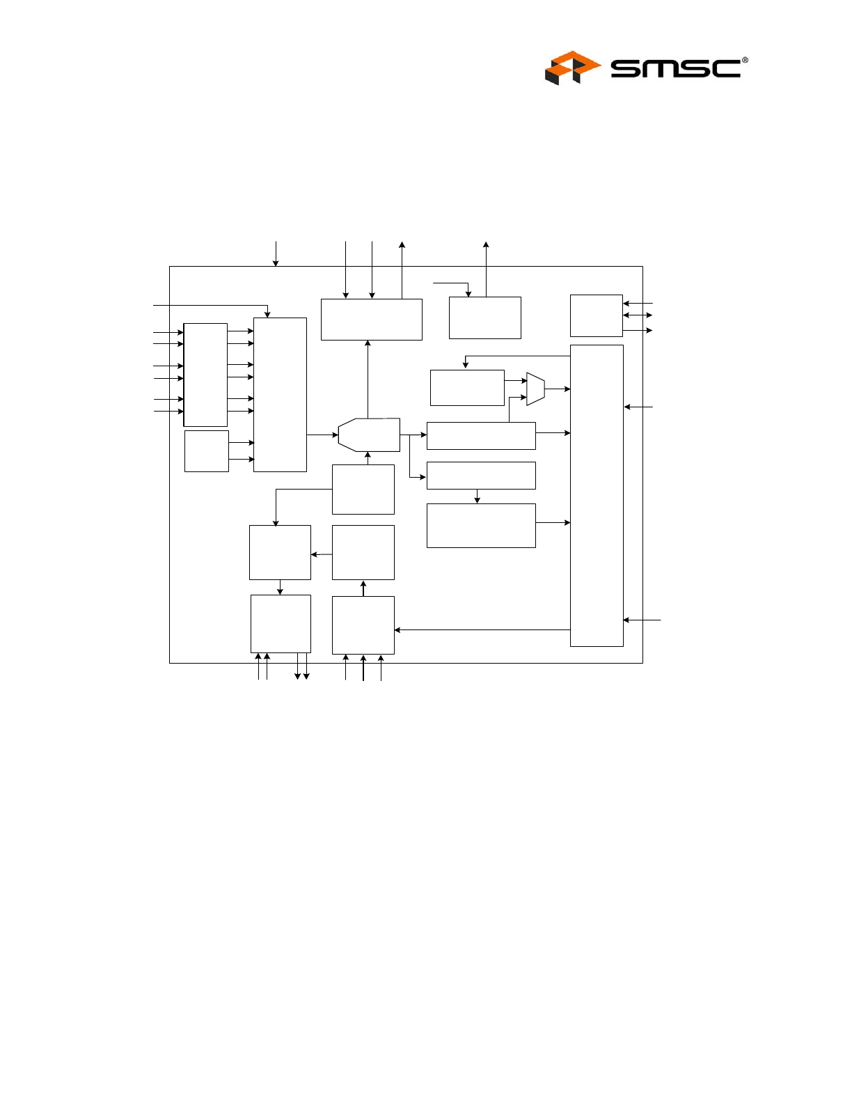
Chapter 1 Block Diagram
Figure 1.1 EMC2102 Block Diagram
Analog
Mux
External
Temp
Diodes
Internal
Temp
Diode
11 bit
Σ Δ
ADC
Ext. Temp Registers
Register
Set and
Logic
DP1
SMCLK
SMDATA
Ext Temp
Limit
Registers
ALERT#
Voltage Reading
DN1
DP2
DN2
DP3
DN3
TRIP_SET
Critical / Thermal
Shutdown Logic
High Side
Fan Driver
8-bit DAC
FA
N
(
2
)
V
D
D
_5V (2)
TH
E
R
MTR
IP#
SMBus
Slave
Protocol
S
YS_S
H
D
N
#
POWER_OK
Bandgap
Reference
Automatic
Fan Control
Algorithms
SH
DN
_
S
EL
CLK_S
E
L
TACH
Monitor
Reset
Generator
RE
SET
#
TA
CH
FAN_MODE
Voltage ->
Temperature
Converison
CLK_I
N
V
D
D
_3V
VDD_5V
RPM-Based Fan Controller with HW Thermal Shutdown
Datasheet
Revision 2.02 (05-17-07)
8
SMSC EMC2102
DATASHEET
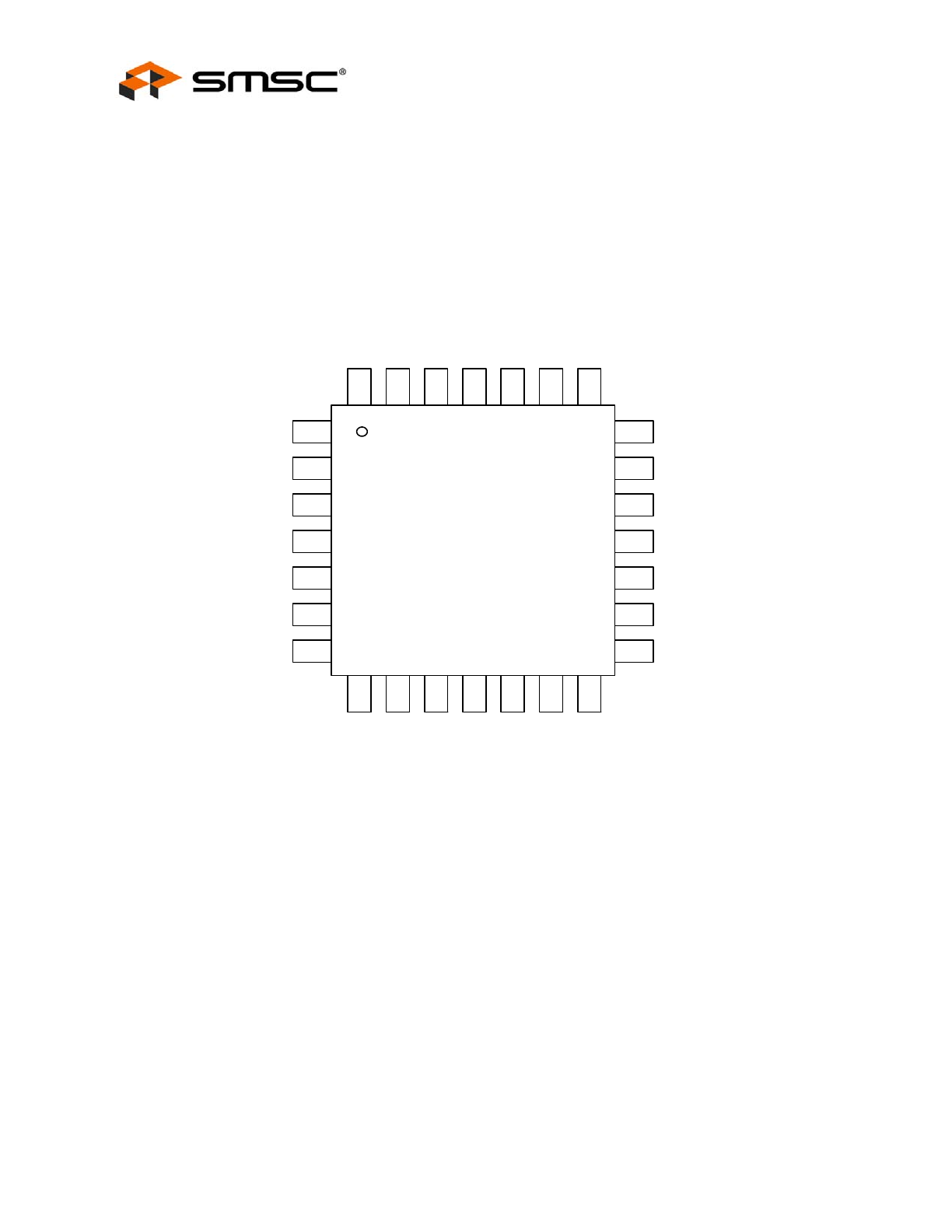
Chapter 2 Pinout
2.1
Pin Layout for EMC2102
Figure 2.1 EMC2102 Pin Diagram
DN1
EMC2102
5 x 5 QFN
1
2
3
4
5
8
9
10
11
12
DP1
T
R
IP_SET
6
7
13
14
21
20
19
18
17
16
15
28
27
26
25
24
23
22
VDD_3V
SM
CLK
DN2
DP2
DN3
DP3
VDD_5V
VDD_5V
FAN
FAN
TAC
H
SM
DAT
A
ALERT#
SYS
_S
HDN#
TH
ERM
T
R
IP
#
PO
W
E
R_
O
K
RESET#
CLK_SEL
GND
CLK_IN
SH
DN
_
S
EL
FAN
_
MODE
N/C
N/
C
N/C

RPM-Based Fan Controller with HW Thermal Shutdown
Datasheet
SMSC EMC2102
9
Revision 2.02 (05-17-07)
DATASHEET
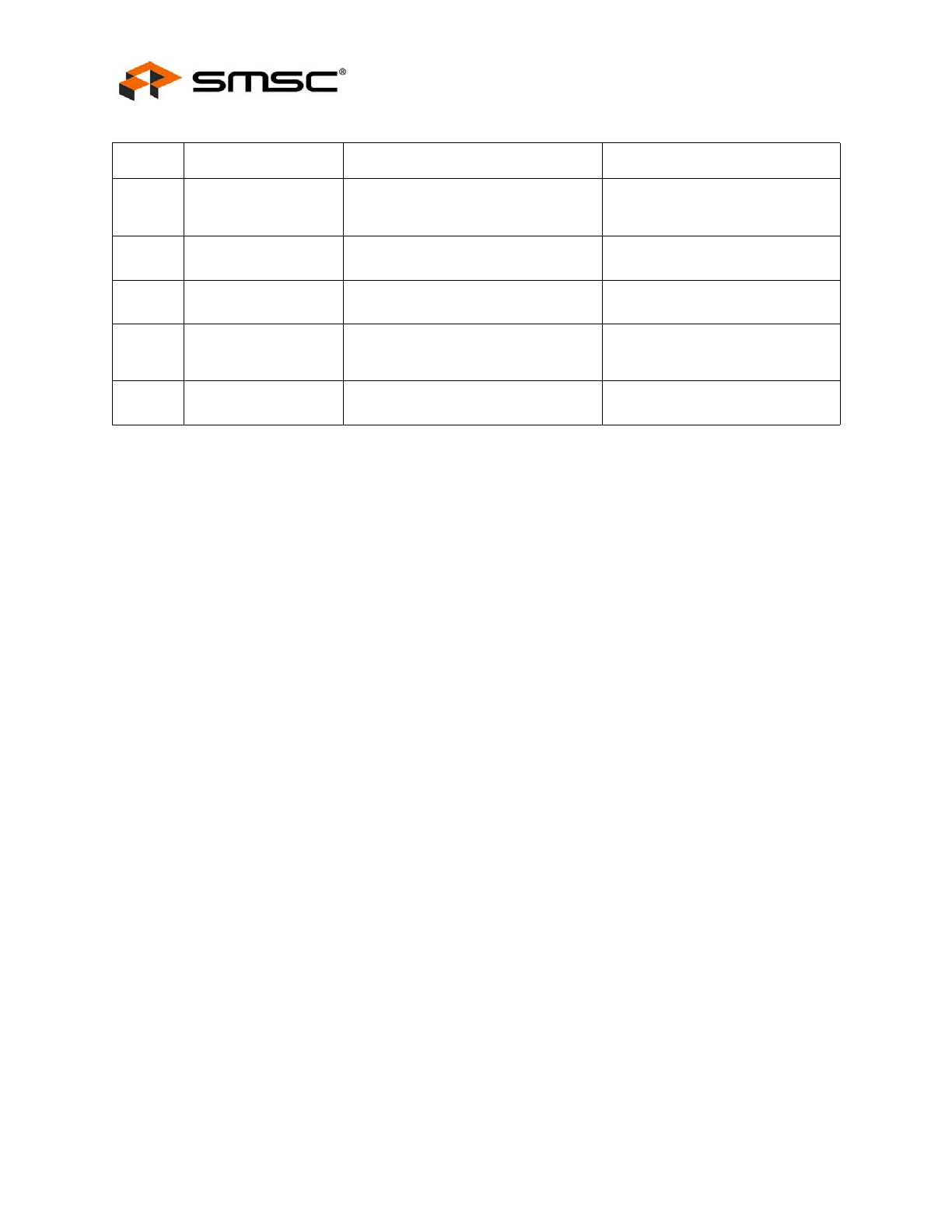
2.2
Pin Description for EMC2102
Table 2.1 Pin Description
PIN NAME
FUNCTION
TYPE
1
VDD_3V
Supply Connection of 3.3V.
Power
2
DN1
Negative (cathode) Analog Input for
External Diode 1.
AIO
3
DP1
Positive (anode) Analog Input for
External Diode 1.
AIO
4
DN2
Negative (cathode) Analog Input for
External Diode 2.
AIO
5
DP2
Positive (anode) Analog Input for
External Diode 2.
AIO
6
DN3
Negative (cathode) Analog Input for
External Diode 3.
AIO
7
DP3
Positive (anode) Analog Input for
External Diode 3.
AIO
8
N/C
Not internally connected.
N/A
9
SHDN_SEL
Determines HW Shutdown
temperature channel (see
Table 5.4,
"SHDN_SEL Pin Configuration"
.)
DIT
10
FAN_MODE
Selects power-up default for fan drive
setting.
DIT
11
TRIP_SET
Voltage input to determine HW
Shutdown threshold temperature
AI
12
SYS_SHDN#
Active low Critical System Shutdown
output
OD (5V)
13
THERMTRIP#
Active low Critical temperature limit
signal from the CPU or chipset.
IP
14
POWER_OK
Active high power good input.
DI (5V)
15
N/C
Not internally connected.
N/A
16
RESET#
Active low reset output.
DO
17
CLK_SEL
Selects internal oscillator or external
clock.
DI (5V)
18
CLK_IN
32.768KHz clock input.
DI (5V)
19
ALERT#
Active low interrupt.
OD (5V)
20
GND
GND connection.
Power
21
N/C
Not internally connected.
N/A
22
SMDATA
SMBus data input/output.
DIOD (5V) - requires external upll-
up resistor
23
SMCLK
SMBus clock input.
DI (5V) - requires external pull-up
resistor
RPM-Based Fan Controller with HW Thermal Shutdown
Datasheet
Revision 2.02 (05-17-07)
10
SMSC EMC2102
DATASHEET
The pin type are described in detail below. All pins labelled with (5V) are 5V tolerant.:
Power - this pin is used to supply power to the device.
DI - Digital Input - this pin is used as a digital input. This pin is 5V tolerant.
AI - Analog Input - this pin is used as an input for analog signals.
AO - Analog Output - this pin is used as an output for analog signals.
AIO - Analog Input / Output - this pin is used as an I/O for analog signals.
DO - Push / Pull Digital Output - this pin is used as a digital output. It can both source and sink current
and doesn’t require a pull-up resistor.
DIOD - Open Drain Digital Input / Output - this pin is used as an digital I/O. It is open drain and requires
a pull-up resistor. This pin is 5V tolerant.
OD - Open Drain Digital Output - this pin is used as a digital output. It is open drain and requires a
pull-up resistor.
DIT - Tri-stated Digital Input - this pin is a digital input that supports 3 logic levels at the input: logic
high, logic low, or high impedance (open).
IP - Digital Input - this pin has an internal 30uA pull-up current to VDD_3V.
24
VDD_5V
5V supply input for the linear fan
driver. Both VDD_5V pins should be
connected to same 5V supply.
Power
25
FAN
Linear fan drive signal. Both FAN pins
should be connected together.
AO
26
FAN
Linear fan drive signal. Both FAN pins
should be connected together.
AO
27
VDD_5V
5V supply input for the linear fan
driver. Both VDD_5V pins should be
connected to same 5V supply.
Power
28
TACH
Input from the tachometer pin of the
fan.
DI (5V)
Table 2.1 Pin Description (continued)
PIN NAME
FUNCTION
TYPE