
2014 Microchip Technology Inc.
DS20005275A-page 1
Data Sheet
PRODUCT FEATURES
EMC1428
1°C Multiple Temperature Sensor with HW
Thermal Shutdown & Hottest of Thermal Zones
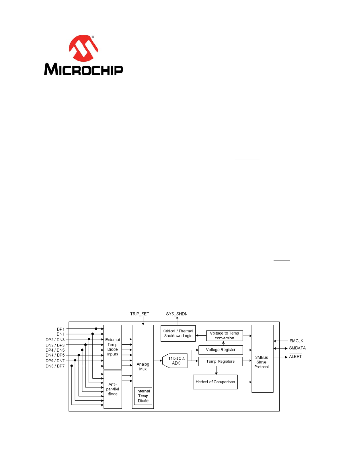
General Description
The EMC1428 is a high accuracy, low cost, System
Management Bus (SMBus) temperature sensor.
Advanced features such as Resistance Error Correction
(REC), Beta Compensation (to CPU diodes requiring the
BJT or transistor model) and automatic diode type
detection combine to provide a robust solution for
complex environmental monitoring applications.
Additionally, the EMC1428 provides a hardware
programmable system shutdown feature that is
programmed at part power-up via a single TRIP_SET
voltage channel that cannot be masked or corrupted
through the SMBus.
The EMC1428 provides ±1° accuracy for external diode
temperatures and ±2°C accuracy for the internal diode
t e m p e r a t u r e . T h e d e v i c e m o n i t o r s u p t o e i g h t
temperature channels (up to seven external and one
internal).
Applications
Notebook Computers
Desktop Computers
Industrial
Embedded Applications
Features
Hardware Thermal Shutdown
—
triggers dedicated SYS_SHDN pin
—
hardware configured range 65°C to 127°C in 1°C steps
—
cannot be disabled or modified by software
Supports diodes requiring the BJT or transistor model
Resistance Error Correction (up to 100 Ohms)
Up to seven External Temperature Monitors
—
±1°C Accuracy (60°C < T
DIODE
< 100°C)
—
0.125°C Resolution
—
Supports up to 2.2nF filter capacitor
— Anti-parallel diodes for extra diode support and
compact design
Internal Temperature Monitor
—
±2°C accuracy
3.3V Supply Voltage
Available in a 16-pin 4mm x 4mm QFN RoHS
Compliant package
Programmable temperature limits for ALERT
Block Diagram
ORDER NUMBERS:
Reel Size is 4,000 pieces
This product meets the halogen maximum concentration values per IEC61249-2-21
ORDERING NUMBER
PACKAGE
FEATURES
DIODE MODES
SUPPORTED
SMBUS
ADDRESS
EMC1428-1-AP-TR
16-pin QFN
(RoHS Compliant)
Up to 7 external diodes. “Hottest Of”
temperature comparison. Hardware
set Critical / Thermal shutdown,
ALERT output
Intel CPU and
3904
1001_100(r/w)
EMC1428-6-AP-TR
16-pin QFN
(RoHS Compliant)
Up to 7 external diodes. “Hottest Of”
temperature comparison. Hardware
set Critical / Thermal shutdown,
ALERT output
Intel CPU and
3904
1001_101(r/w)
EMC1428-7-AP-TR-
CB7
16-pin QFN
(RoHS Compliant)
Up to 7 external diodes. “Hottest Of”
temperature comparison. Hardware
set Critical / Thermal shutdown,
ALERT output
Intel CPU and
3904
Selected by
pull-up resistor
on SYS_SHDN
pin
1°C Multiple Temperature Sensor with HW Thermal Shutdown & Hottest of Thermal Zones
Data Sheet
DS20005275A-page 2
2014 Microchip Technology Inc.
TO OUR VALUED CUSTOMERS
It is our intention to provide our valued customers with the best documentation possible to ensure successful use of your Microchip
products. To this end, we will continue to improve our publications to better suit your needs. Our publications will be refined and
enhanced as new volumes and updates are introduced.
If you have any questions or comments regarding this publication, please contact the Marketing Communications Department via
E-mail at
docerrors@microchip.com
. We welcome your feedback.
Most Current Data Sheet
To obtain the most up-to-date version of this data sheet, please register at our Worldwide Web site at:
http://www.microchip.com
You can determine the version of a data sheet by examining its literature number found on the bottom outside corner of any page.
The last character of the literature number is the version number, (e.g., DS30000000A is version A of document DS30000000).
Errata
An errata sheet, describing minor operational differences from the data sheet and recommended workarounds, may exist for cur-
rent devices. As device/documentation issues become known to us, we will publish an errata sheet. The errata will specify the
revision of silicon and revision of document to which it applies.
To determine if an errata sheet exists for a particular device, please check with one of the following:
• Microchip’s Worldwide Web site;
http://www.microchip.com
• Your local Microchip sales office (see last page)
When contacting a sales office, please specify which device, revision of silicon and data sheet (include -literature number) you are
using.
Customer Notification System
Register on our web site at
www.microchip.com
to receive the most current information on all of our products.

1°C Multiple Temperature Sensor with HW Thermal Shutdown & Hottest of Thermal Zones
Data Sheet
2014 Microchip Technology Inc.
DS20005275A-page 3
Table of Contents
Chapter 1 Pin Description . . . . . . . . . . . . . . . . . . . . . . . . . . . . . . . . . . . . . . . . . . . . . . . . . . . . . . 7
Chapter 2 Electrical Specifications . . . . . . . . . . . . . . . . . . . . . . . . . . . . . . . . . . . . . . . . . . . . . . . 9
2.1 Absolute Maximum Ratings. . . . . . . . . . . . . . . . . . . . . . . . . . . . . . . . . . . . . . . . . . . . . . . . . . . . . . . . . . 9
2.2 Electrical Specifications. . . . . . . . . . . . . . . . . . . . . . . . . . . . . . . . . . . . . . . . . . . . . . . . . . . . . . . . . . . . . 9
2.3 SMBus Electrical Characteristics. . . . . . . . . . . . . . . . . . . . . . . . . . . . . . . . . . . . . . . . . . . . . . . . . . . . . 11
Chapter 3 System Management Bus Interface Protocol . . . . . . . . . . . . . . . . . . . . . . . . . . . . . 12
3.1 System Management Bus Interface Protocol . . . . . . . . . . . . . . . . . . . . . . . . . . . . . . . . . . . . . . . . . . . 12
3.2 Write Byte . . . . . . . . . . . . . . . . . . . . . . . . . . . . . . . . . . . . . . . . . . . . . . . . . . . . . . . . . . . . . . . . . . . . . . 12
3.3 Read Byte . . . . . . . . . . . . . . . . . . . . . . . . . . . . . . . . . . . . . . . . . . . . . . . . . . . . . . . . . . . . . . . . . . . . . . 13
3.4 Send Byte . . . . . . . . . . . . . . . . . . . . . . . . . . . . . . . . . . . . . . . . . . . . . . . . . . . . . . . . . . . . . . . . . . . . . . 13
3.5 Receive Byte . . . . . . . . . . . . . . . . . . . . . . . . . . . . . . . . . . . . . . . . . . . . . . . . . . . . . . . . . . . . . . . . . . . . 13
3.6 Alert Response Address . . . . . . . . . . . . . . . . . . . . . . . . . . . . . . . . . . . . . . . . . . . . . . . . . . . . . . . . . . . 13
3.7 SMBus Address. . . . . . . . . . . . . . . . . . . . . . . . . . . . . . . . . . . . . . . . . . . . . . . . . . . . . . . . . . . . . . . . . . 14
3.8 SMBus Timeout . . . . . . . . . . . . . . . . . . . . . . . . . . . . . . . . . . . . . . . . . . . . . . . . . . . . . . . . . . . . . . . . . . 14
Chapter 4 Product Description . . . . . . . . . . . . . . . . . . . . . . . . . . . . . . . . . . . . . . . . . . . . . . . . . 15
4.1 ALERT Output . . . . . . . . . . . . . . . . . . . . . . . . . . . . . . . . . . . . . . . . . . . . . . . . . . . . . . . . . . . . . . . . . . . 16
4.1.1 ALERT Pin Interrupt Mode. . . . . . . . . . . . . . . . . . . . . . . . . . . . . . . . . . . . . . . . . . . . . . . . . . . 16
4.1.2 ALERT Pin Comparator Mode . . . . . . . . . . . . . . . . . . . . . . . . . . . . . . . . . . . . . . . . . . . . . . . . 16
4.2 SYS_SHDN Output . . . . . . . . . . . . . . . . . . . . . . . . . . . . . . . . . . . . . . . . . . . . . . . . . . . . . . . . . . . . . . . 16
4.3 TRIP_SET Pin . . . . . . . . . . . . . . . . . . . . . . . . . . . . . . . . . . . . . . . . . . . . . . . . . . . . . . . . . . . . . . . . . . . 17
4.4 Consecutive Alerts. . . . . . . . . . . . . . . . . . . . . . . . . . . . . . . . . . . . . . . . . . . . . . . . . . . . . . . . . . . . . . . . 19
4.5 Temperature Monitoring . . . . . . . . . . . . . . . . . . . . . . . . . . . . . . . . . . . . . . . . . . . . . . . . . . . . . . . . . . . 19
4.5.1 Resistance Error Correction . . . . . . . . . . . . . . . . . . . . . . . . . . . . . . . . . . . . . . . . . . . . . . . . . 20
4.5.2 Beta Compensation . . . . . . . . . . . . . . . . . . . . . . . . . . . . . . . . . . . . . . . . . . . . . . . . . . . . . . . . 20
4.5.3 Digital Averaging . . . . . . . . . . . . . . . . . . . . . . . . . . . . . . . . . . . . . . . . . . . . . . . . . . . . . . . . . . 20
4.5.4 “Hottest Of” Comparison . . . . . . . . . . . . . . . . . . . . . . . . . . . . . . . . . . . . . . . . . . . . . . . . . . . . 20
4.5.5 Conversion Rates . . . . . . . . . . . . . . . . . . . . . . . . . . . . . . . . . . . . . . . . . . . . . . . . . . . . . . . . . 21
4.5.6 Dynamic Averaging . . . . . . . . . . . . . . . . . . . . . . . . . . . . . . . . . . . . . . . . . . . . . . . . . . . . . . . . 21
4.6 Diode Connections . . . . . . . . . . . . . . . . . . . . . . . . . . . . . . . . . . . . . . . . . . . . . . . . . . . . . . . . . . . . . . . 21
4.6.1 Diode Faults. . . . . . . . . . . . . . . . . . . . . . . . . . . . . . . . . . . . . . . . . . . . . . . . . . . . . . . . . . . . . . 22
Chapter 5 Register Description . . . . . . . . . . . . . . . . . . . . . . . . . . . . . . . . . . . . . . . . . . . . . . . . . 23
5.1 Data Read Interlock. . . . . . . . . . . . . . . . . . . . . . . . . . . . . . . . . . . . . . . . . . . . . . . . . . . . . . . . . . . . . . . 28
5.2 Temperature Data Registers . . . . . . . . . . . . . . . . . . . . . . . . . . . . . . . . . . . . . . . . . . . . . . . . . . . . . . . . 28
5.3 Status Register . . . . . . . . . . . . . . . . . . . . . . . . . . . . . . . . . . . . . . . . . . . . . . . . . . . . . . . . . . . . . . . . . . 30
5.4 Configuration Register. . . . . . . . . . . . . . . . . . . . . . . . . . . . . . . . . . . . . . . . . . . . . . . . . . . . . . . . . . . . . 30
5.5 Conversion Rate Register . . . . . . . . . . . . . . . . . . . . . . . . . . . . . . . . . . . . . . . . . . . . . . . . . . . . . . . . . . 31
5.6 Limit Registers. . . . . . . . . . . . . . . . . . . . . . . . . . . . . . . . . . . . . . . . . . . . . . . . . . . . . . . . . . . . . . . . . . . 32
5.7 Therm Hysteresis Register . . . . . . . . . . . . . . . . . . . . . . . . . . . . . . . . . . . . . . . . . . . . . . . . . . . . . . . . . 35
5.8 Therm Limit Registers . . . . . . . . . . . . . . . . . . . . . . . . . . . . . . . . . . . . . . . . . . . . . . . . . . . . . . . . . . . . . 35
5.9 External Diode Fault Register . . . . . . . . . . . . . . . . . . . . . . . . . . . . . . . . . . . . . . . . . . . . . . . . . . . . . . . 36
5.10 TRIP_SET Reading Register. . . . . . . . . . . . . . . . . . . . . . . . . . . . . . . . . . . . . . . . . . . . . . . . . . . . . . . 36
5.11 Software Thermal Shutdown Configuration Register . . . . . . . . . . . . . . . . . . . . . . . . . . . . . . . . . . . . 36
5.12 Hardware Critical / Thermal Shutdown Limit Register . . . . . . . . . . . . . . . . . . . . . . . . . . . . . . . . . . . . 37
5.13 Channel Interrupt Mask Register. . . . . . . . . . . . . . . . . . . . . . . . . . . . . . . . . . . . . . . . . . . . . . . . . . . . 37

1°C Multiple Temperature Sensor with HW Thermal Shutdown & Hottest of Thermal Zones
Data Sheet
DS20005275A-page 4
2014 Microchip Technology Inc.
5.14 Consecutive ALERT Register . . . . . . . . . . . . . . . . . . . . . . . . . . . . . . . . . . . . . . . . . . . . . . . . . . . . . . 38
5.15 Beta Configuration Register . . . . . . . . . . . . . . . . . . . . . . . . . . . . . . . . . . . . . . . . . . . . . . . . . . . . . . . 40
5.16 Hottest Temperature Registers . . . . . . . . . . . . . . . . . . . . . . . . . . . . . . . . . . . . . . . . . . . . . . . . . . . . . 41
5.17 Hottest Temperature Status Register . . . . . . . . . . . . . . . . . . . . . . . . . . . . . . . . . . . . . . . . . . . . . . . . 41
5.18 High Limit Status Register . . . . . . . . . . . . . . . . . . . . . . . . . . . . . . . . . . . . . . . . . . . . . . . . . . . . . . . . . 42
5.19 Low Limit Status Register . . . . . . . . . . . . . . . . . . . . . . . . . . . . . . . . . . . . . . . . . . . . . . . . . . . . . . . . . 43
5.20 THERM Limit Status Register . . . . . . . . . . . . . . . . . . . . . . . . . . . . . . . . . . . . . . . . . . . . . . . . . . . . . . 43
5.21 REC Configuration Register . . . . . . . . . . . . . . . . . . . . . . . . . . . . . . . . . . . . . . . . . . . . . . . . . . . . . . . 44
5.22 Hottest Configuration Register . . . . . . . . . . . . . . . . . . . . . . . . . . . . . . . . . . . . . . . . . . . . . . . . . . . . . 44
5.23 Channel Configuration Register . . . . . . . . . . . . . . . . . . . . . . . . . . . . . . . . . . . . . . . . . . . . . . . . . . . . 45
5.24 Filter Control Register . . . . . . . . . . . . . . . . . . . . . . . . . . . . . . . . . . . . . . . . . . . . . . . . . . . . . . . . . . . . 46
5.25 Product ID Register . . . . . . . . . . . . . . . . . . . . . . . . . . . . . . . . . . . . . . . . . . . . . . . . . . . . . . . . . . . . . . 46
5.26 Manufacturer ID Register (FEh) . . . . . . . . . . . . . . . . . . . . . . . . . . . . . . . . . . . . . . . . . . . . . . . . . . . . 46
5.27 Revision Register (FFh). . . . . . . . . . . . . . . . . . . . . . . . . . . . . . . . . . . . . . . . . . . . . . . . . . . . . . . . . . . 47
Chapter 6 Package Information . . . . . . . . . . . . . . . . . . . . . . . . . . . . . . . . . . . . . . . . . . . . . . . . 48
6.1 EMC1428 Package Drawing . . . . . . . . . . . . . . . . . . . . . . . . . . . . . . . . . . . . . . . . . . . . . . . . . . . . . . . . 48
6.2 Package Markings . . . . . . . . . . . . . . . . . . . . . . . . . . . . . . . . . . . . . . . . . . . . . . . . . . . . . . . . . . . . . . . . 50
6.2.1 EMC1428-X-AP (16-Pin QFN). . . . . . . . . . . . . . . . . . . . . . . . . . . . . . . . . . . . . . . . . . . . . . . . 50
Chapter 7 Data Sheet Revision History . . . . . . . . . . . . . . . . . . . . . . . . . . . . . . . . . . . . . . . . . . 51

1°C Multiple Temperature Sensor with HW Thermal Shutdown & Hottest of Thermal Zones
Data Sheet
2014 Microchip Technology Inc.
DS20005275A-page 5
List of Figures
Figure 1.1 EMC1428 Pin Diagram . . . . . . . . . . . . . . . . . . . . . . . . . . . . . . . . . . . . . . . . . . . . . . . . . . . . . . 7
Figure 3.1 SMBus Timing Diagram . . . . . . . . . . . . . . . . . . . . . . . . . . . . . . . . . . . . . . . . . . . . . . . . . . . . . 12
Figure 4.1 System Diagram for EMC1428 . . . . . . . . . . . . . . . . . . . . . . . . . . . . . . . . . . . . . . . . . . . . . . . 15
Figure 4.2 Block Diagram of Hardware Thermal Shutdown . . . . . . . . . . . . . . . . . . . . . . . . . . . . . . . . . . 17
Figure 4.3 Vset Circuit. . . . . . . . . . . . . . . . . . . . . . . . . . . . . . . . . . . . . . . . . . . . . . . . . . . . . . . . . . . . . . . 18
Figure 4.4 Diode Connections. . . . . . . . . . . . . . . . . . . . . . . . . . . . . . . . . . . . . . . . . . . . . . . . . . . . . . . . . 22
Figure 6.1 16-Pin QFN 4mm x 4mm Package Dimensions. . . . . . . . . . . . . . . . . . . . . . . . . . . . . . . . . . . 48
Figure 6.2 16-Pin QFN 4mm x 4mm Package Drawing . . . . . . . . . . . . . . . . . . . . . . . . . . . . . . . . . . . . . 49
Figure 6.3 16-Pin QFN 4mm x 4mm PCB Footprint . . . . . . . . . . . . . . . . . . . . . . . . . . . . . . . . . . . . . . . . 50

1°C Multiple Temperature Sensor with HW Thermal Shutdown & Hottest of Thermal Zones
Data Sheet
DS20005275A-page 6
2014 Microchip Technology Inc.
List of Tables
Table 1.1 EMC1428 Pin Description . . . . . . . . . . . . . . . . . . . . . . . . . . . . . . . . . . . . . . . . . . . . . . . . . . . . . 7
Table 1.2 Pin Type. . . . . . . . . . . . . . . . . . . . . . . . . . . . . . . . . . . . . . . . . . . . . . . . . . . . . . . . . . . . . . . . . . . 8
Table 2.1 Absolute Maximum Ratings . . . . . . . . . . . . . . . . . . . . . . . . . . . . . . . . . . . . . . . . . . . . . . . . . . . . 9
Table 2.2 Electrical Specifications . . . . . . . . . . . . . . . . . . . . . . . . . . . . . . . . . . . . . . . . . . . . . . . . . . . . . . . 9
Table 2.3 SMBus Electrical Specifications . . . . . . . . . . . . . . . . . . . . . . . . . . . . . . . . . . . . . . . . . . . . . . . 11
Table 3.1 Protocol Format . . . . . . . . . . . . . . . . . . . . . . . . . . . . . . . . . . . . . . . . . . . . . . . . . . . . . . . . . . . . 12
Table 3.2 Write Byte Protocol . . . . . . . . . . . . . . . . . . . . . . . . . . . . . . . . . . . . . . . . . . . . . . . . . . . . . . . . . 12
Table 3.3 Read Byte Protocol . . . . . . . . . . . . . . . . . . . . . . . . . . . . . . . . . . . . . . . . . . . . . . . . . . . . . . . . . 13
Table 3.4 Send Byte Protocol . . . . . . . . . . . . . . . . . . . . . . . . . . . . . . . . . . . . . . . . . . . . . . . . . . . . . . . . . 13
Table 3.5 Receive Byte Protocol . . . . . . . . . . . . . . . . . . . . . . . . . . . . . . . . . . . . . . . . . . . . . . . . . . . . . . . 13
Table 3.6 Alert Response Address Protocol . . . . . . . . . . . . . . . . . . . . . . . . . . . . . . . . . . . . . . . . . . . . . . 14
Table 3.7 Address Select Decode on SYS_SHDN Pin . . . . . . . . . . . . . . . . . . . . . . . . . . . . . . . . . . . . . . 14
Table 4.1 V
TRIP
Resistor Settings . . . . . . . . . . . . . . . . . . . . . . . . . . . . . . . . . . . . . . . . . . . . . . . . . . . . . . 18
Table 4.2 Supply Current vs. Conversion Rate for EMC1428 . . . . . . . . . . . . . . . . . . . . . . . . . . . . . . . . . 21
Table 5.1 Register Set in Hexadecimal Order . . . . . . . . . . . . . . . . . . . . . . . . . . . . . . . . . . . . . . . . . . . . . 23
Table 5.2 Temperature Data Registers . . . . . . . . . . . . . . . . . . . . . . . . . . . . . . . . . . . . . . . . . . . . . . . . . . 28
Table 5.3 Temperature Data Format . . . . . . . . . . . . . . . . . . . . . . . . . . . . . . . . . . . . . . . . . . . . . . . . . . . . 29
Table 5.4 Status Register . . . . . . . . . . . . . . . . . . . . . . . . . . . . . . . . . . . . . . . . . . . . . . . . . . . . . . . . . . . . 30
Table 5.5 Configuration Register . . . . . . . . . . . . . . . . . . . . . . . . . . . . . . . . . . . . . . . . . . . . . . . . . . . . . . . 30
Table 5.6 Conversion Rate Register . . . . . . . . . . . . . . . . . . . . . . . . . . . . . . . . . . . . . . . . . . . . . . . . . . . . 31
Table 5.7 Conversion Rate . . . . . . . . . . . . . . . . . . . . . . . . . . . . . . . . . . . . . . . . . . . . . . . . . . . . . . . . . . . 31
Table 5.8 Maximum Conversion Rate Per Temperature Channels . . . . . . . . . . . . . . . . . . . . . . . . . . . . . 32
Table 5.9 Temperature Limit Registers . . . . . . . . . . . . . . . . . . . . . . . . . . . . . . . . . . . . . . . . . . . . . . . . . . 32
Table 5.10 Therm Hysteresis Register . . . . . . . . . . . . . . . . . . . . . . . . . . . . . . . . . . . . . . . . . . . . . . . . . . . 35
Table 5.11 Therm Limit Registers . . . . . . . . . . . . . . . . . . . . . . . . . . . . . . . . . . . . . . . . . . . . . . . . . . . . . . . 35
Table 5.12 External Diode Fault Register . . . . . . . . . . . . . . . . . . . . . . . . . . . . . . . . . . . . . . . . . . . . . . . . . 36
Table 5.13 TRIP_SET Reading Register. . . . . . . . . . . . . . . . . . . . . . . . . . . . . . . . . . . . . . . . . . . . . . . . . . 36
Table 5.14 Software Thermal Shutdown Configuration Register. . . . . . . . . . . . . . . . . . . . . . . . . . . . . . . . 36
Table 5.15 Hardware Thermal Shutdown Limit Register . . . . . . . . . . . . . . . . . . . . . . . . . . . . . . . . . . . . . . 37
Table 5.16 Channel Interrupt Mask Register . . . . . . . . . . . . . . . . . . . . . . . . . . . . . . . . . . . . . . . . . . . . . . . 37
Table 5.17 Consecutive ALERT Register . . . . . . . . . . . . . . . . . . . . . . . . . . . . . . . . . . . . . . . . . . . . . . . . . 38
Table 5.18 Consecutive Alert Settings. . . . . . . . . . . . . . . . . . . . . . . . . . . . . . . . . . . . . . . . . . . . . . . . . . . . 39
Table 5.19 Beta Configuration Register. . . . . . . . . . . . . . . . . . . . . . . . . . . . . . . . . . . . . . . . . . . . . . . . . . . 40
Table 5.20 Beta Compensation Look Up Table. . . . . . . . . . . . . . . . . . . . . . . . . . . . . . . . . . . . . . . . . . . . . 40
Table 5.21 Hottest Temperature Registers . . . . . . . . . . . . . . . . . . . . . . . . . . . . . . . . . . . . . . . . . . . . . . . . 41
Table 5.22 Hottest Temperature Register . . . . . . . . . . . . . . . . . . . . . . . . . . . . . . . . . . . . . . . . . . . . . . . . . 41
Table 5.23 High Limit Status Register . . . . . . . . . . . . . . . . . . . . . . . . . . . . . . . . . . . . . . . . . . . . . . . . . . . . 42
Table 5.24 Low Limit Status Register . . . . . . . . . . . . . . . . . . . . . . . . . . . . . . . . . . . . . . . . . . . . . . . . . . . . 43
Table 5.25 THERM Limit Status Register . . . . . . . . . . . . . . . . . . . . . . . . . . . . . . . . . . . . . . . . . . . . . . . . . 43
Table 5.26 REC Configuration Register . . . . . . . . . . . . . . . . . . . . . . . . . . . . . . . . . . . . . . . . . . . . . . . . . . 44
Table 5.27 Hottest Configuration Register. . . . . . . . . . . . . . . . . . . . . . . . . . . . . . . . . . . . . . . . . . . . . . . . . 44
Table 5.28 Channel Configuration Register. . . . . . . . . . . . . . . . . . . . . . . . . . . . . . . . . . . . . . . . . . . . . . . . 45
Table 5.29 Filter Control Register . . . . . . . . . . . . . . . . . . . . . . . . . . . . . . . . . . . . . . . . . . . . . . . . . . . . . . . 46
Table 5.30 Product ID Register . . . . . . . . . . . . . . . . . . . . . . . . . . . . . . . . . . . . . . . . . . . . . . . . . . . . . . . . . 46
Table 5.31 Manufacturer ID Register. . . . . . . . . . . . . . . . . . . . . . . . . . . . . . . . . . . . . . . . . . . . . . . . . . . . . 46
Table 5.32 Revision Register. . . . . . . . . . . . . . . . . . . . . . . . . . . . . . . . . . . . . . . . . . . . . . . . . . . . . . . . . . . 47
Table 7.1 Revision History. . . . . . . . . . . . . . . . . . . . . . . . . . . . . . . . . . . . . . . . . . . . . . . . . . . . . . . . . . . . 51
1°C Multiple Temperature Sensor with HW Thermal Shutdown & Hottest of Thermal Zones
Data Sheet
2014 Microchip Technology Inc.
DS20005275A-page 7
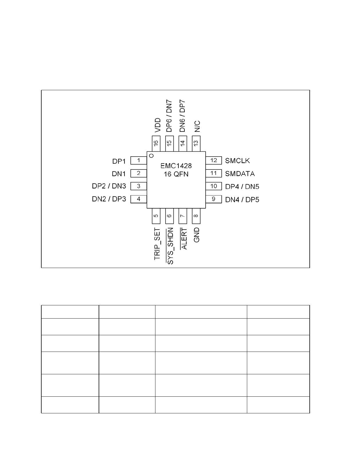
Chapter 1 Pin Description
Figure 1.1 EMC1428 Pin Diagram
Table 1.1 EMC1428 Pin Description
PIN NUMBER
NAME
FUNCTION
TYPE
1
DP1
DP1 - External Diode 1 positive
(anode) connection.
AIO
2
DN1
External Diode 1 negative (cathode)
connection.
AIO
3
DP2 / DN3
External Diode 2 positive (anode)
connection and External Diode 3
negative (cathode) connection
AIO
4
DN2 / DP3
External diode 2 negative (cathode)
connection and External Diode 3
positive (anode) connection
AIO
5
TRIP_SET
Voltage input to set Critical / Thermal
Shutdown temperature
AIO

1°C Multiple Temperature Sensor with HW Thermal Shutdown & Hottest of Thermal Zones
Data Sheet
DS20005275A-page 8
2014 Microchip Technology Inc.
The pin types are described below. All pins labelled (5V) are 5V tolerant.
APPLICATION NOTE: For the 5V tolerant pins that have a pull-up resistor, the voltage difference between VDD and
the pull-up voltage must never exceed 3.6V.
6
SYS_SHDN
Active low System Shutdown output
signal - requires pull-up resistor
EMC1428-7 - The pull-up resistor is
used to determine SMBus address
OD (5V)
7
ALERT
Active low interrupt - requires pull-up
resistor
OD (5V)
8
GND
Ground Connection
Power
9
DN4 / DP5
External diode 4 negative (cathode)
connection and External Diode 5
positive (anode) connection
AIO
10
DP4 / DN5
External Diode 4 positive (anode)
connection and External Diode 5
negative (cathode) connection
AIO
11
SMDATA
SMBus Data input/output - requires
pull-up resistor
DIOD (5V)
12
SMCLK
SMBus Clock input - requires pull-up
resistor
DI (5V)
13
N/C
Not used - connect to Ground - see
EMC1428 Anomaly Sheet
n/a
14
DN6 / DP7
External diode 6 negative (cathode)
connection and External Diode 7
positive (anode) connection
AIO
15
DP6 / DN7
External Diode 6 positive (anode)
connection and External Diode 7
negative (cathode) connection
AIO
16
VDD
Power supply
Power
Table 1.2 Pin Type
PIN TYPE
FUNCTION
Power
Used to supply either VDD or GND to the device
DI
5V tolerant digital input
OD
5V tolerant Open drain digital output. Requires a pull-up resistor
DIOD
5V tolerant bi-directional digital input / open-drain output. Requires a pull-up
resistor.
AIO
Analog input / output used for external diodes or analog inputs
Table 1.1 EMC1428 Pin Description (continued)
PIN NUMBER
NAME
FUNCTION
TYPE

1°C Multiple Temperature Sensor with HW Thermal Shutdown & Hottest of Thermal Zones
Data Sheet
2014 Microchip Technology Inc.
DS20005275A-page 9
Chapter 2 Electrical Specifications
2.1
Absolute Maximum Ratings
Note: Stresses at or above those listed could cause permanent damage to the device. This is a stress
rating only and functional operation of the device at any other condition above those indicated
in the operation sections of this specification is not implied. When powering this device from
laboratory or system power supplies, it is important that the Absolute Maximum Ratings not be
exceeded or device failure can result. Some power supplies exhibit voltage spikes on their
outputs when the AC power is switched on or off. In addition, voltage transients on the AC
power line may appear on the DC output. If this possibility exists, it is suggested that a clamp
circuit be used.
Note 2.1
For the 5V tolerant pins that have a pull-up resistor, the pull-up voltage must not exceed
3.6V when the device is unpowered.
2.2
Electrical Specifications
Table 2.1 Absolute Maximum Ratings
DESCRIPTION
RATING
UNIT
Supply Voltage (V
DD
)
-0.3 to 4.0
V
Voltage on 5V tolerant pins (V
5VT_pin
)
-0.3 to 5.5
V
Voltage on 5V tolerant pins (|V
5VT_pin
- V
DD
|) (see
Note 2.1
)
-0.3 to 3.6
V
Voltage on any other pin to Ground
-0.3 to V
DD
+0.3
V
Operating Temperature Range
-40 to +125
°C
Storage Temperature Range
-55 to +150
°C
Lead Temperature Range
Refer to JEDEC Spec. J-STD-
020
Package Thermal Characteristics for QFN-16
Thermal Resistance (
j-a
)
50
°C/W
ESD Rating, All pins HBM
2000
V
Table 2.2 Electrical Specifications
V
DD
= 3.0V to 3.6V, T
A
= -40°C to 125°C, all typical values at T
A
= 27°C unless otherwise noted.
CHARACTERISTIC
SYMBOL
MIN
TYP
MAX
UNITS
CONDITIONS
DC Power
Supply Voltage
V
DD
3.0
3.3
3.6
V

1°C Multiple Temperature Sensor with HW Thermal Shutdown & Hottest of Thermal Zones
Data Sheet
DS20005275A-page 10
2014 Microchip Technology Inc.
Note 2.2
If a 1% resistor is used for RSET, then it is guaranteed to decode as shown in
Table 4.1
.
Supply Current
I
DD
450
600
uA
1 conversion / sec, dynamic
averaging disabled
Supply Current
I
DD
900
1200
uA
4 conversions / sec, dynamic
averaging enabled
Internal Temperature Monitor
Temperature Accuracy
±0.25
±1
°C
0°C < T
A
< 100°C
±2
°C
-40°C < T
A
< 125°C
Temperature Resolution
0.125
°C
External Temperature Monitor
Temperature Accuracy
±0.25
±1
°C
+40°C < T
DIODE
< +110°C
0°C < T
A
< 110°C
±0.5
±2
°C
-40°C < T
DIODE
< 127°C
Temperature Resolution
0.125
°C
Conversion Time all
Channels
t
CONV
190
ms
default settings
Capacitive Filter
C
FILTER
2.2
2.7
nF
Connected across external diode
Resistance Error
Correction
R
SERIES
100
In series with DP and DN lines
TRIP_SET Measurement
Decoded Temperature
Accuracy
T
SET
0.5
°C
R
SET
= 1% resistor
(see
Note 2.2
)
ALERT and SYS_SHDN pins
Output Low Voltage
V
OL
0.4
V
I
SINK
= 8mA
Leakage Current
I
LEAK
±5
uA
powered or unpowered
T
A
< 85°C
pull-up voltage < 3.6V
Power Up Timing
First conversion ready
t
CONV_f
300
ms
Time after power up before all
channels updated with valid data
SMBus delay
t
SMB_d
15
ms
Delay before SMBus
communications should be sent by
host
Table 2.2 Electrical Specifications (continued)
V
DD
= 3.0V to 3.6V, T
A
= -40°C to 125°C, all typical values at T
A
= 27°C unless otherwise noted.
CHARACTERISTIC
SYMBOL
MIN
TYP
MAX
UNITS
CONDITIONS