
2001-2012 Microchip Technology Inc.
DS21440D-page 1
TC622/TC624
Features:
• Temperature Set Point Easily Programs with a
Single External Resistor
• Operates with 2.7V Power Supply (TC624)
• TO-220 Package for Direct Mounting to Heatsink
(TC622XAT) or Standard 8-Pin PDIP and SOIC
Applications:
• Power Supply Over-Temperature Detection
• Consumer Electronics
• Fire/Heat Detection
• UPSs, Amplifiers, Motors
• CPU Thermal Management in PCs
General Description:
The TC622 and TC624 are programmable solid-state
temperature sensors designed to replace mechanical
switches in sensing and control applications. Both
devices integrate the temperature sensor with a
voltage reference and all required detector circuitry.
The desired temperature set point is set by the user
with a single external resistor.
Ambient temperature is sensed and compared to the
programmed set point. The OUT and OUT outputs are
driven to their active state when the measured
temperature exceeds the programmed set point.
The TC622 has a power supply voltage range of 4.5V
to 18.0V while the TC624 operates over a power supply
range of 2.7V to 4.5V. Both devices are usable over a
temperature range of -40°C to +125°C (TC622VXX,
TC624VXX). Both devices feature low supply current
making them suitable for portable applications.
Eight-pin through-hole and surface mount packages
are available. The TC622 is also offered in a 5-pin
TO-220 package.
The TC622 and TC624 are single point temperature
detectors ideal for use in a wide variety of applications.
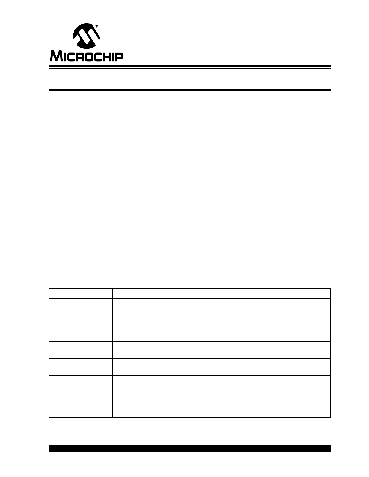
Device Selection Table
Part Number
Voltage Operation
Package
Ambient Temperature
TC622COA
4.5V to 18V
8-Pin SOIC
0°C to +70°C
TC622CPA
4.5V to 18V
8-Pin PDIP
0°C to +70°C
TC622EAT
4.5V to 18V
5-Pin TO-220
-40°C to +85°C
TC622EOA
4.5V to 18V
8-Pin SOIC
-40°C to +85°C
TC622EPA
4.5V to 18V
8-Pin PDIP
-40°C to +85°C
TC622VAT
4.5V to 18V
5-Pin TO-220
-40°C to +125°C
TC622VOA
4.5V to 18V
8-Pin SOIC
-40°C to +125°C
TC622VPA
4.5V to 18V
8-Pin PDIP
-40°C to +125°C
TC624COA
2.7V to 4.5V
8-Pin SOIC
0°C to +70°C
TC624CPA
2.7V to 4.5V
8-Pin PDIP
0°C to +70°C
TC624EOA
2.7V to 4.5V
8-Pin SOIC
-40°C to +85°C
TC624EPA
2.7V to 4.5V
8-Pin PDIP
-40°C to +85°C
TC624VOA
2.7V to 4.5V
8-Pin SOIC
-40°C to +125°C
TC624VPA
2.7V to 4.5V
8-Pin PDIP
-40°C to +125°
Low Cost Single Trip Point Temperature Sensor
TC622/TC624
DS21440D-page 2
2001-2012 Microchip Technology Inc.
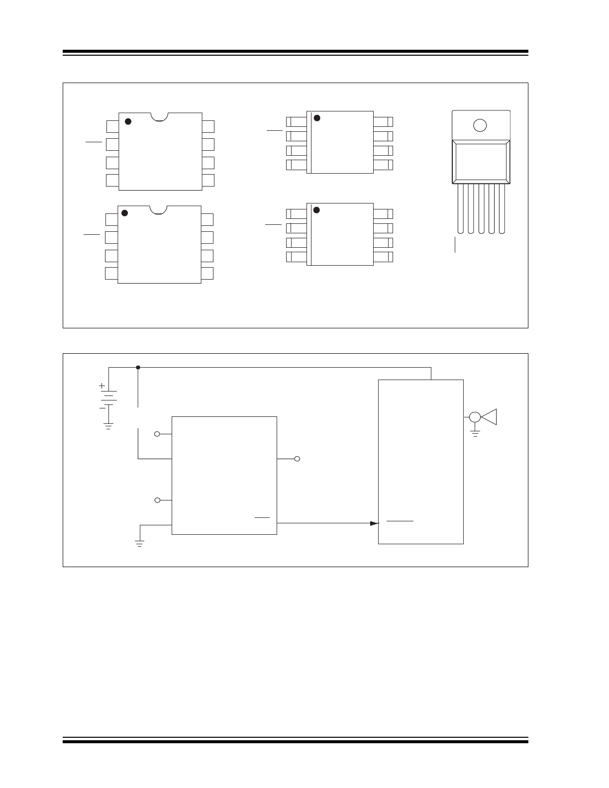
Package Type
Functional Block Diagram
GND
NC
OUT
OUT
NC
NC
V
DD
V
DD
GND
NC
T
SET
T
SET
NC
OUT
OUT
NC
GND
NC
OUT
OUT
NC
NC
V
DD
T
SET
GND
NC
OUT
OUT
NC
NC
V
DD
T
SET
V
DD
T
SET
OUT
OUT
GND
1 2 3 4 5
TC622EAT
TC622VAT
8
7
6
5
1
2
3
4
1
8
2
7
3
6
4
5
8
7
6
5
1
2
3
4
1
8
2
7
3
6
4
5
TC622CPA
TC622EPA
TC622VPA
TC624CPA
TC624EPA
TC624VPA
TC622COA
TC622EOA
TC622VOA
TC624COA
TC624EOA
TC624VOA
PDIP
SOT-220
SOIC
Note: For TO-220 Package, Pin 3 is connected to case heatsink.
TC622
R
SET
+9V
T
SET
GND
V
DD
OUT
NC
OUT
NC
NC
1
3
4
5
6
7
8
Microcontrollers
ALARM
Horn
9V
Battery
TC624
2
2001-2012 Microchip Technology Inc.
DS21440D-page 3
TC622/TC624
1.0
ELECTRICAL
CHARACTERISTICS
Absolute Maximum Ratings*
Supply Voltage (TC622) ......................................... 20V
(TC624) ........................................ 5.5V
Input Voltage Any Input .. (GND – 0.3V) to (V
DD
+0.3V)
Operating Temperature ...................... -40°C to +125°C
C Version .............................. 0°C to +70°C
E Version ........................... -40°C to +85°C
V Version ......................... -40°C to +125°C
Storage Temperature ......................... -65°C to +150°C
Stresses above those listed under “Absolute Maximum
Ratings” may cause permanent damage to the device.
These are stress ratings only and functional operation
of the device at these or any other conditions above
those indicated in the operation sections of the specifi-
cations is not implied. Exposure to Absolute Maximum
Rating conditions for extended periods may affect
device reliability.
.
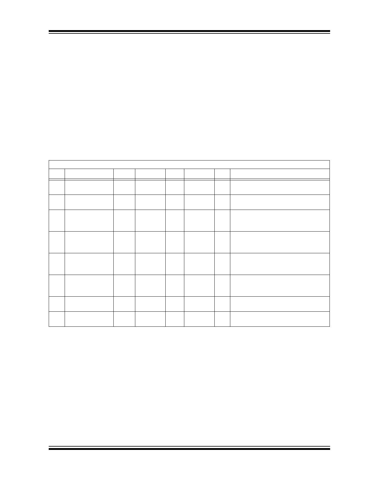
TC622/TC624 ELECTRICAL SPECIFICATIONS
Electrical Characteristics: Over operating temperature range, unless otherwise specified.
Sym
Parameter
Device
Min
Typ
Max
Unit Test
Conditions
V
DD
Supply Voltage
Range
TC622
TC624
4.5
2.7
—
—
18
4.5
V
I
DD
Supply Current
TC622
TC624
—
—
200
170
600
300
A 5.0V V
DD
18V
2.7V
V
DD
4.5V
V
OH
Output Voltage
(High)
TC622 0.90 x V
DD
0.80 x V
DD
—
—
—
—
V
5.0V
V
DD
18V, -40°C T
A
+125°C,
I
OH
= 250
A
I
OH
= 500
A
V
OL
Output Voltage
(Low)
TC622
—
—
—
—
—
—
0.15 x V
DD
0.30 x V
DD
0.35 x V
DD
V
-40°C
T
A
+85°C, I
OL
= 500
A
I
OL
= 1 mA
-40°C
T
A
+125°C, I
OL
= 1 mA
V
OH
Output Voltage
(High)
TC624
—
0.90 x V
DD
0.80 x V
DD
—
—
—
—
V
2.7V
V
DD
4.5V
-40°C
T
A
+125°C, I
OH
= 250
A
I
OH
= 500
A
V
OL
Output Voltage
(Low)
TC624
—
—
—
—
—
—
0.1 x V
DD
0.2 x V
DD
0.25 x V
DD
V
-40°C
T
A
+85°C, I
OL
= 500
A
I
OL
= 1 mA
-40°C
T
A
+125°C, I
OL
= 1 mA
T
SET
Absolute Accuracy TC622
TC624
T - 5
T - 5
T ± 1
T ± 1
T + 5
T + 5
°C T
SET
= Programmed Temperature
T
SET
= Programmed Temperature
OUT Trip Point
Hysteresis
TC622
TC624
—
—
2
2
—
—
°C
TC622/TC624
DS21440D-page 4
2001-2012 Microchip Technology Inc.
2.0
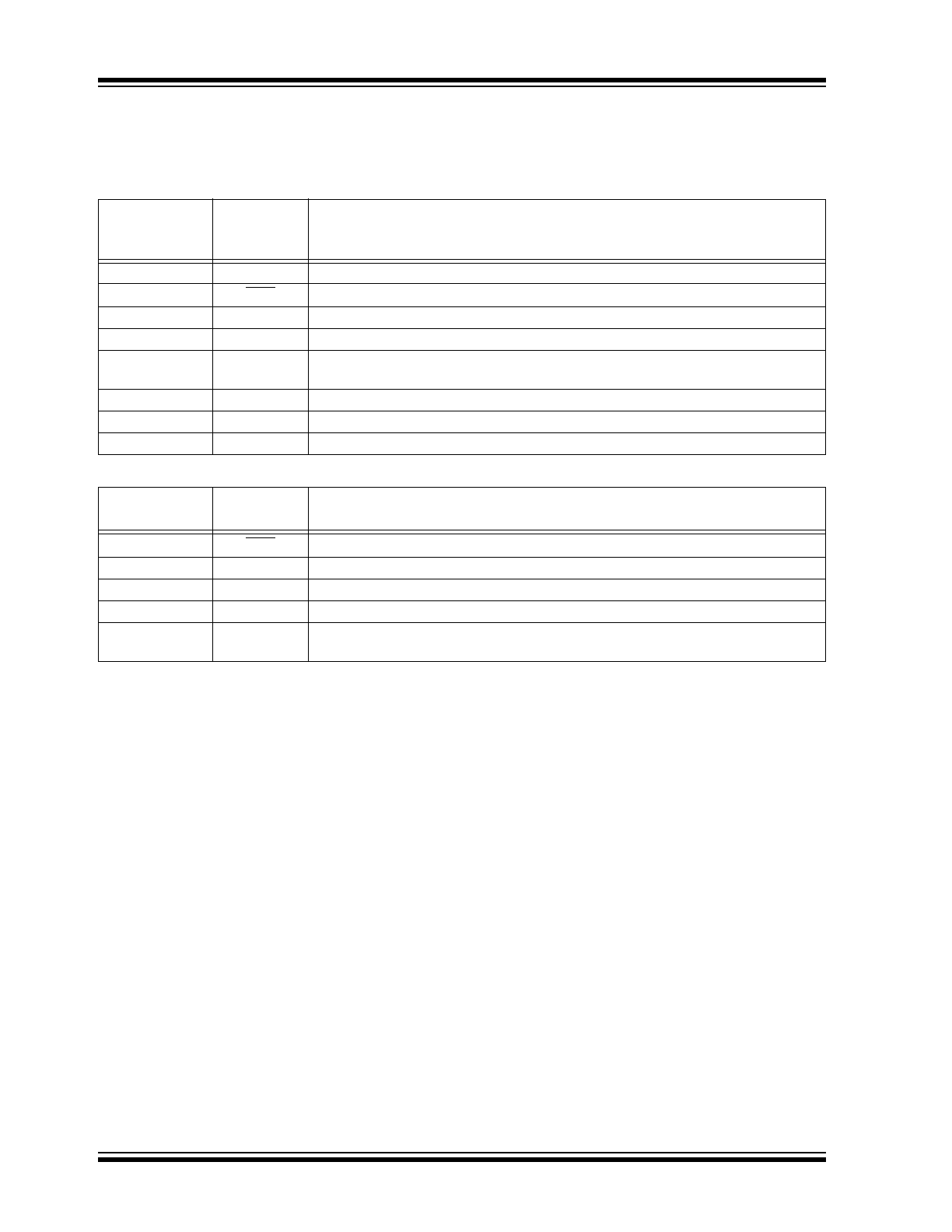
PIN DESCRIPTION
The descriptions of the pins are listed in Table 2-1.
TABLE 2-1:
PIN FUNCTION TABLE
Pin No.
(8-Pin SOIC)
(8-Pin PDIP)
Symbol
Description
1
NC
No Internal Connection.
2
OUT
Active low output.
3
OUT
Active high output.
4
GND
Ground Terminal.
5
T
SET
Temperature set point. Connect an external 1% resistor from T
SET
to V
CC
to set
trip point.
6
NC
No Internal Connection.
7
V
DD
Power supply input.
8
NC
No Internal Connection.
Pin No.
(5-Pin SOT-220)
Symbol
Description
1
OUT
Active low output.
2
OUT
Active high output.
3
V
DD
Power supply input.
4
GND
Ground Terminal.
5
T
SET
Temperature set point. Connect an external 1% resistor from T
SET
to V
CC
to set
trip point.
2001-2012 Microchip Technology Inc.
DS21440D-page 5
TC622/TC624
3.0
DETAILED DESCRIPTION
3.1
Trip Point Programming
When the temperature of the device exceeds the pro-
grammed temperature trip point, T
SET
, the OUT and
OUT outputs are driven into their active states. The
desired trip point temperature is programmed with a
single external resistor connected between the T
SET
input and V
CC
. The relationship between the resistor
value and the trip point temperature is given by
Equation 3-1.
EQUATION 3-1:
For example, as shown in Figure 3-1, to program the
device to trip at 50°C, the programming resistor is:
FIGURE 3-1:
Programming Resistor
Values vs. Temperature
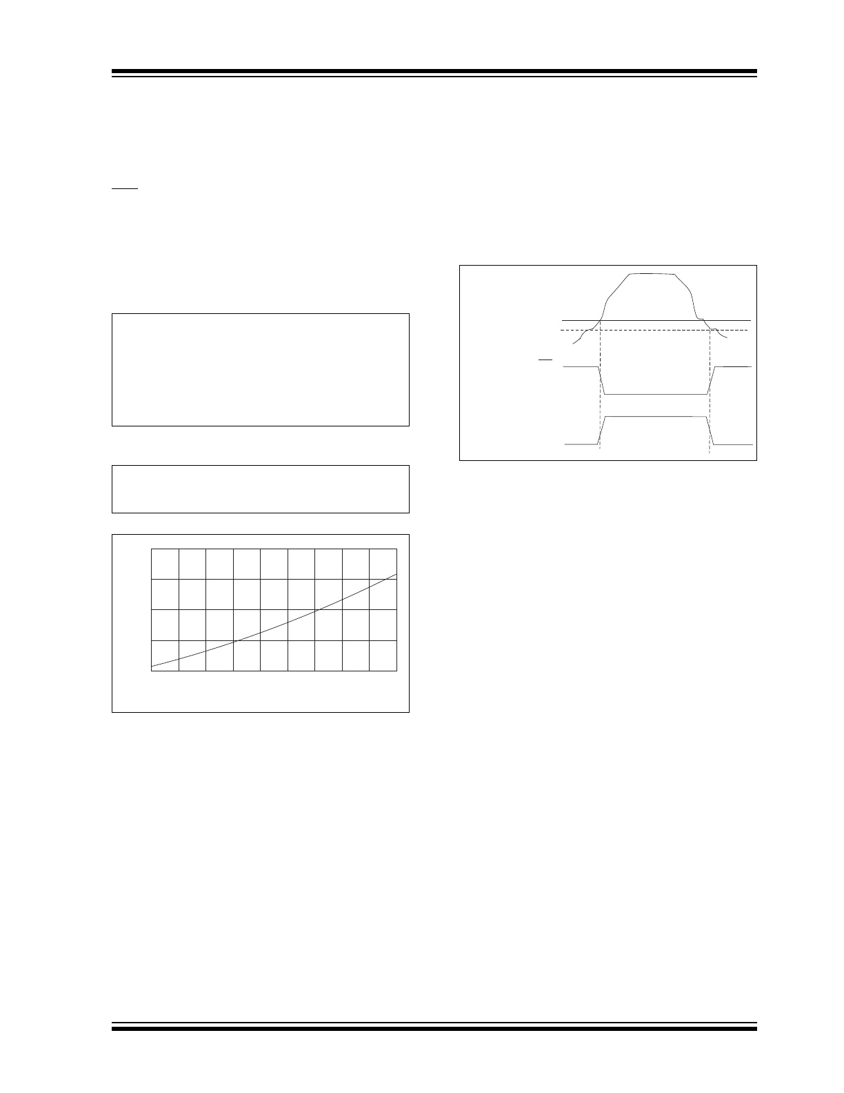
3.2
Hysteresis
To prevent output “chattering” at the trip point tempera-
ture, the temperature detector in the TC622/TC624 has
2°C hysteresis (see Figure 3-2). The outputs are driven
active when the temperature crosses the set point
determined by the external resistor. As temperature
declines below the set point, the hysteresis action will
hold the outputs true until the temperature drops 2°C
below the threshold.
FIGURE 3-2:
TC622/TC624 Hysteresis
R
TRIP
= 0.5997 x T
2.1312
Where:
R
TRIP
= Programming resistor value in Ohms
T = Desired trip temperature in degrees Kelvin.
R
TRIP
= 0.5997 x ((50 + 273.15)
2.1312
) = 133.65 k
TEMPERATURE (°C)
RESISTANCE, R
TRIP
(k
Ω
)
-55
-35
-15
5
25
45
65
85
105
125
50
100
150
200
250
Set Point
Temperature
OUT
(Set Point – 2 Degrees C)
OUT
TC622/TC624
DS21440D-page 6
2001-2012 Microchip Technology Inc.
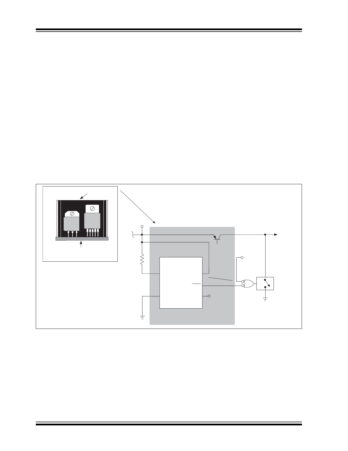
4.0
TYPICAL APPLICATIONS
4.1
Over-Temperature Shutdown
The TC622 can be used to create a simple over-tem-
perature shutdown circuit. In this circuit, temperature is
sensed within the system enclosure (internal system
ambient) or at the heatsink itself. When measured
temperature exceeds a preset limit, a fault is indicated
and the system shuts down.
Figure 4-1 illustrates an over-temperature shutdown
circuit using the TC622 sensor in a single TO-220
package, allowing direct attachment to the heatsink
surface. As shown, the TC622 outputs are driven active
when the heatsink temperature equals the trip point
temperature set by R
TRIP
. When this happens, the
crowbar circuit is activated, causing the supply output
to fold back to zero. The TC622 outputs remain active
until the heatsink temperature falls a minimum of 2°C
(built-in hysteresis) below the trip point temperature, at
which time the device again allows normal supply
operation.
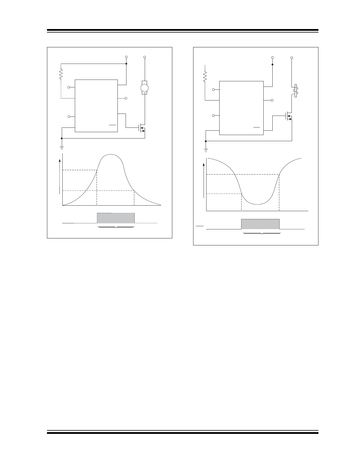
4.2
Cooling and Heating Applications
The TC622/TC624 can be used to control a DC fan as
shown in Figure 4-2. The fan turns on when the sensed
temperature rises above T
SET
and remains on until the
temperature falls below T
SET
- 2°C.
Figure 4-3 shows the TC622 acting as a heater
thermostat. Circuit operation is identical to that of the
cooling fan application.
FIGURE 4-1:
TC622 Power Supply Over-Temperature Shutdown
Heatsink
Circuit Board
TC622 Heatsink Mounting
TC622
TC622
R
TRIP
V
CC
Output Device
Heatsink Surface
Power Good
Signal
OVERTEMP
Crowbar
Circuit
T
SET
GND
V
DD
V
OUT
OUT
OUT
Output
Device
2001-2012 Microchip Technology Inc.
DS21440D-page 7
TC622/TC624
FIGURE 4-2:
TC624 As A Fan Controller
for Notebook PC
FIGURE 4-3:
TC622 As A Heater
Thermostat
TC624
R
SET
+2.7 to 4.5V +12V
T
SET
GND
V
DD
OUT
NC
N-Channel
Logic Level
MOSFET
DC Fan
OUT
NC
NC
1
3
4
5
6
7
8
Temperature
OUT
Fan "On"
T
SET
– 2 C
T
SET
+
2
TC622
R
SET
+4.5 to 18.0V
+12V
T
SET
GND
V
DD
OUT
NC
N-Channel
Level Logic
MOSFET
OUT
1
2
4
5
6
7
8
NC
NC
Temperature
OUT
Heater "On"
T
SET
– 2 C
T
SET
Heater
TC622/TC624
DS21440D-page 8
2001-2012 Microchip Technology Inc.
5.0
PACKAGING INFORMATION
5.1
Package Marking Information
Package marking data not available at this time.
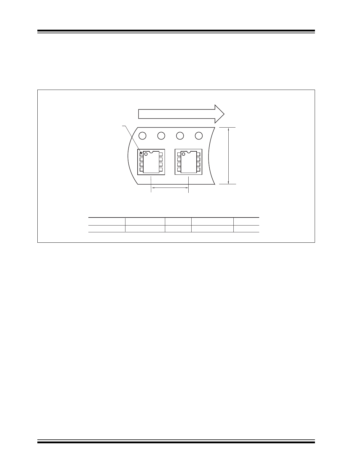
5.2
Taping Form
Component Taping Orientation for 8-Pin SOIC (Narrow) Devices
Package
Carrier Width (W)
Pitch (P)
Part Per Full Reel
Reel Size
8-Pin SOIC (N)
12 mm
8 mm
2500
13 in
Carrier Tape, Number of Components Per Reel and Reel Size
Standard Reel Component Orientation
for 713 Suffix Device
Pin 1
User Direction of Feed
P
W
2001-2012 Microchip Technology Inc.
DS21440D-page 9
TC622/TC624
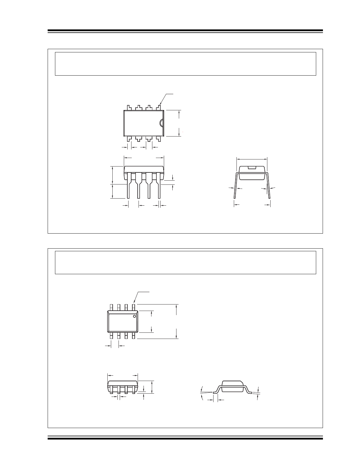
5.3
Package Dimensions
5.4
Package Dimensions (Continued)
3° Min.
Pin 1
.260 (6.60)
.240 (6.10)
.045 (1.14)
.030 (0.76)
.070 (1.78)
.040 (1.02)
.400 (10.16)
.348 (8.84)
.200 (5.08)
.140 (3.56)
.150 (3.81)
.115 (2.92)
.110 (2.79)
.090 (2.29)
.022 (0.56)
.015 (0.38)
.040 (1.02)
.020 (0.51)
.015 (0.38)
.008 (0.20)
.310 (7.87)
.290 (7.37)
.400 (10.16)
.310 (7.87)
8-Pin Plastic DIP
Dimensions: inches (mm)
Note:
For the most current package drawings, please see the Microchip Packaging Specification located
at http://www.microchip.com/packaging
.050 (1.27) Typ.
8
°
Max.
Pin 1
.244 (6.20)
.228 (5.79)
.157 (3.99)
.150 (3.81)
.197 (5.00)
.189 (4.80)
.020 (0.51)
.013 (0.33)
.010 (0.25)
.004 (0.10)
.069 (1.75)
.053 (1.35)
.010 (0.25)
.007 (0.18)
.050 (1.27)
.016 (0.40)
8-Pin SOIC
Dimensions: inches (mm)
Note:
For the most current package drawings, please see the Microchip Packaging Specification located
at http://www.microchip.com/packaging
TC622/TC624
DS21440D-page 10
2001-2012 Microchip Technology Inc.
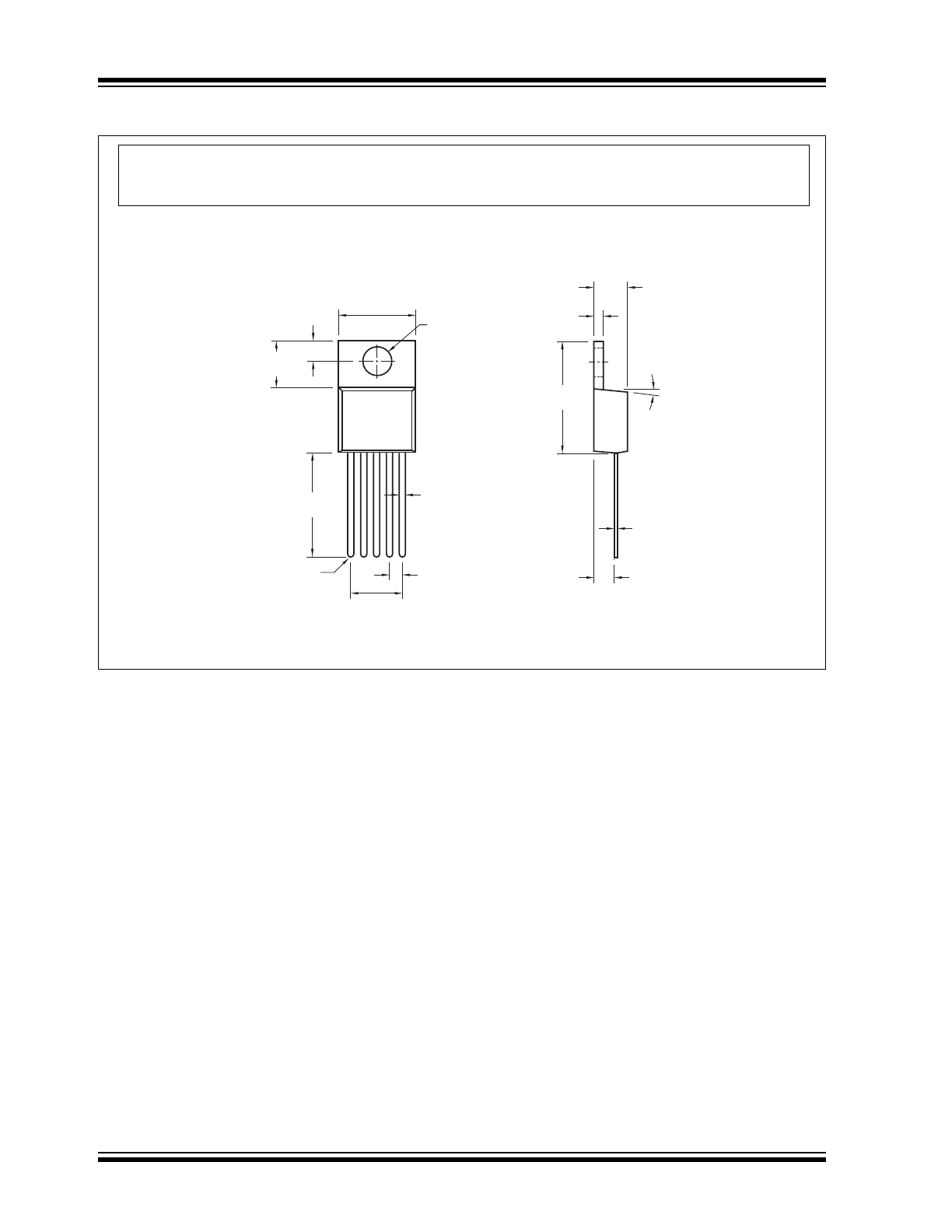
5-Pin TO-220
.273 (6.93)
.263 (6.68)
.037 (0.95)
.025 (0.64)
.117 (2.97)
.103 (2.62)
.415 (10.54)
.390 (9.91)
.156 (3.96)
.140 (3.56)
Dia.
.293 (7.44)
.204 (5.18)
.590 (14.99)
.482 (12.24)
.072 (1.83)
.062 (1.57)
Pin 1
.185 (4.70)
.165 (4.19)
.055 (1.40)
.045 (1.14)
.613 (15.57)
.569 (14.45)
.115 (2.92)
.087 (2.21)
.025 (0.64)
.012 (0.30)
3° - 7.5°
5 PLCS.
Dimensions: inches (mm)
Note:
For the most current package drawings, please see the Microchip Packaging Specification located
at http://www.microchip.com/packaging