
_______________General Description
The MAX504/MAX515 are low-power, voltage-output,
10-bit digital-to-analog converters (DACs) specified for
single +5V power-supply operation. The MAX504 can
also be operated with ±5V supplies. The MAX515
draws only 140µA, and the MAX504 (with internal refer-
ence) draws only 260µA. The MAX515 comes in 8-pin
DIP and SO packages, while the MAX504 comes in 14-
pin DIP and SO packages. Both parts have been
trimmed for offset voltage, gain, and linearity, so no fur-
ther adjustment is necessary.
The MAX515’s buffer is fixed at a gain of 2. The MAX504’s
internal op amp may be configured for a gain of 1 or 2, as
well as for unipolar or bipolar output voltages. The
MAX504 can also be used as a four-quadrant multiplier
without external resistors or op amps.
For parallel data inputs, see the MAX503 data sheet.
For a hardware and software compatible 12-bit
upgrade, refer to the MAX531/MAX538/MAX539 data
sheet.
_______________________Applications
Battery-Powered Test Instruments
Digital Offset and Gain Adjustment
Battery-Operated/Remote Industrial Controls
Machine and Motion Control Devices
Cellular Telephones
___________________________Features
♦
Operate from Single +5V Supply
♦
Buffered Voltage Output
♦
Internal 2.048V Reference (MAX504)
♦
140µA Supply Current (MAX515)
♦
INL = ±1/2LSB (max)
♦
Guaranteed Monotonic Over Temperature
♦
Flexible Output Ranges:
0V to V
DD
(MAX504/MAX515)
V
SS
to V
DD
(MAX504)
♦
8-Pin SO/DIP (MAX515)
♦
Power-On Reset
♦
Serial Data Output for Daisy-Chaining
______________Ordering Information
MAX504/MAX515
5V, Low-Power, Voltage-Output,
Serial 10-Bit DACs
________________________________________________________________
Maxim Integrated Products
1
1
2
3
4
8
7
6
5
V
DD
VOUT
REFIN
AGND
DOUT
CS
SCLK
DIN
DIP/SO
TOP VIEW
MAX515
_________________Pin Configurations
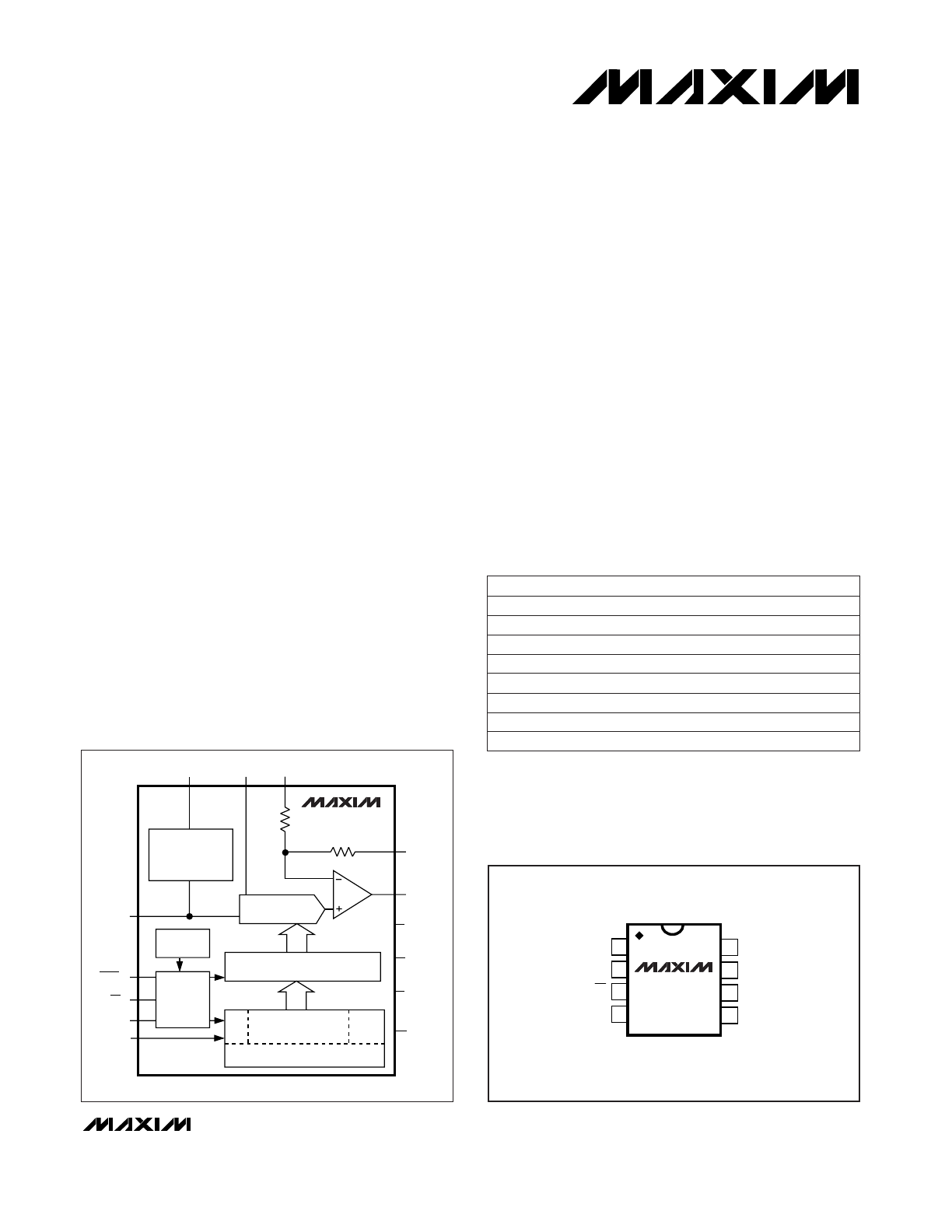
________________Functional Diagram
19-0280; Rev 2; 11/96
PART
TEMP. RANGE
PIN-PACKAGE
MAX504
CPD
0°C to +70°C
14 Plastic DIP
MAX504CSD
0°C to +70°C
14 SO
DAC
10-BIT DAC REGISTER
16-BIT SHIFT REGISTER
4
DUMMY
BITS
CONTROL
LOGIC
POWER-UP
RESET
2.048V
REFERENCE*
AGND
SCLK
DIN
REFOUT*
REFIN BIPOFF*
RFB*
VOUT
V
DD
DGND*
V
SS
*
DOUT
(LSB)
(MSB)
CLR*
CS
10 DATA BITS
2
0s
* MAX504 ONLY
MAX504
MAX515
Refer to the MAX531/MAX538/MAX539 data sheet for military tem-
perature or die equivalents.
MAX504 appears at end of data sheet.
MAX504EPD
-40°C to +85°C
14 Plastic DIP
MAX504ESD
-40°C to +85°C
14 SO
MAX515
CPA
0°C to +70°C
8 Plastic DIP
MAX515EPA
-40°C to +85°C
8 Plastic DIP
MAX515CSA
0°C to +70°C
8 SO
MAX515ESA
-40°C to +85°C
8 SO
For free samples & the latest literature: http://www.maxim-ic.com, or phone 1-800-998-8800.
For small orders, phone 408-737-7600 ext. 3468.
MAX504/MAX515
5V, Low-Power, Voltage-Output
Serial 10-Bit DACs
2
_______________________________________________________________________________________
ABSOLUTE MAXIMUM RATINGS
V
DD
to DGND and V
DD
to AGND ................................-0.3V, +6V
V
SS
to DGND and V
SS
to AGND .................................-6V, +0.3V
V
DD
to V
SS
.................................................................-0.3V, +12V
AGND to DGND........................................................-0.3V, +0.3V
Digital Input Voltage to DGND ......................-0.3V, (V
DD
+ 0.3V)
REFIN ..................................................(V
SS
- 0.3V), (V
DD
+ 0.3V)
REFOUT to AGND .........................................-0.3V, (V
DD
+ 0.3V)
RFB .....................................................(V
SS
- 0.3V), (V
DD
+ 0.3V)
BIPOFF ................................................(V
SS
- 0.3V), (V
DD
+ 0.3V)
V
OUT
(Note 1) ................................................................V
SS
, V
DD
Continuous Current, Any Pin................................-20mA, +20mA
Continuous Power Dissipation (T
A
= +70°C)
8-Pin Plastic DIP (derate 9.09mW/°C above +70°C) .....727mW
8-Pin SO (derate 5.88mW/°C above +70°C)..................471mW
14-Pin Plastic DIP (derate 10.00mW/°C above +70°C) ..... 800mW
14-Pin SO (derate 8.33mW/°C above +70°C)................667mW
Operating Temperature Ranges
MAX5_ _C_ _.........................................................0°C to +70°C
MAX5_ _E_ _ ......................................................-40°C to +85°C
Storage Temperature Range .............................-65°C to +165°C
Lead Temperature (soldering, 10sec) .............................+300°C
ELECTRICAL CHARACTERISTICS—Single +5V Supply
(V
DD
= 5V, V
SS
= 0V, AGND = DGND = 0V, REFIN = 2.048V (external), RFB = BIPOFF = VOUT (MAX504), C
REFOUT
= 33µF (MAX504),
R
L
= 10k
Ω
, C
L
= 100pF, T
A
= T
MIN
to T
MAX
, unless otherwise noted.)
Stresses beyond those listed under “Absolute Maximum Ratings” may cause permanent damage to the device. These are stress ratings only, and functional
operation of the device at these or any other conditions beyond those indicated in the operational sections of the specifications is not implied. Exposure to
absolute maximum rating conditions for extended periods may affect device reliability.
PARAMETER
SYMBOL
MIN
TYP
MAX
UNITS
Unipolar Offset Error
V
OS
0
3
LSB
Differential Nonlinearity
DNL
±1
LSB
Unipolar Offset Tempco
TCV
OS
3
ppm/°C
Gain Error (Note 2)
GE
±1
LSB
Resolution
N
10
Bits
Gain-Error Tempco
1
ppm/°C
Gain-Error Power-Supply
Rejection Ratio
PSRR
0.1
LSB/V
0
V
DD
- 2
Output Voltage Range
0
V
DD
- 0.4
V
Output Load Regulation
0.5
LSB
Short-Circuit Current
I
SC
12
mA
Voltage Range
0
V
DD
- 2
V
Input Resistance
40
k
Ω
Input Capacitance
10
50
pF
AC Feedthrough
-80
dB
CONDITIONS
Guaranteed monotonic
4.5V
≤
V
DD
≤
5.5V
MAX504 (G = 1)
MAX504 (G = 2), MAX515
VOUT = 2V, R
L
= 2k
Ω
Code dependent, minimum at code 0101...
Code dependent (Note 3)
REFIN = 1kHz, 2Vp-p
Note 1:
The output may be shorted to V
DD
, V
SS,
or AGND if the package power dissipation limit is not exceeded.
Relative Accuracy (Note 2)
INL
±0.5
LSB
Unipolar Offset-Error
Power-Supply Rejection Ratio
PSRR
0.1
LSB/V
4.5V
≤
V
DD
≤
5.5V
REFERENCE INPUT (REFIN)
VOLTAGE OUTPUT (V
OUT
)
STATIC PERFORMANCE
MAX504/MAX515
5V, Low-Power, Voltage-Output,
Serial 10-Bit DACs
_______________________________________________________________________________________
3
ELECTRICAL CHARACTERISTICS—Single +5V Supply (continued)
(V
DD
= 5V, V
SS
= 0V, AGND = DGND = 0V, REFIN = 2.048V (external), RFB = BIPOFF = VOUT (MAX504), C
REFOUT
= 33µF (MAX504),
R
L
= 10k
Ω
, C
L
= 100pF, T
A
= T
MIN
to T
MAX
, unless otherwise noted.)
PARAMETER
Input Current
SYMBOL
MIN
TYP
MAX
I
IN
±1
UNITS
Noise Voltage
e
n
µA
400
Input Capacitance
C
IN
µVp-p
Power-Supply Rejection Ratio
8
PSRR
200
µV/V
Resistance
R
REFOUT
0.5
2
pF
Ω
Required External Capacitor
C
REFOUT
3.3
µF
Output High
Input High
V
OH
V
IH
2.4
V
DD
- 1
V
Input Low
V
V
IL
0.8
V
Output Low
V
OL
0.4
V
Voltage-Output Slew Rate
SR
0.15
0.25
V/µs
Voltage-Output Settling Time
25
µs
Digital Feedthrough
2.024
2.048
2.072
5
nV-s
Signal-to-Noise Plus Distortion
SINAD
68
dB
260
400
CONDITIONS
V
IN
= 0V or V
DD
0.1Hz to 10kHz
4.5V
≤
V
DD
≤
5.5V
(Note 4)
I
SOURCE
= 2mA
I
SINK
= 2mA
T
A
= +25°C
To ±1/2LSB, VOUT = 2V
CS = V
DD
, DIN = 100kHz
REFIN = 1kHz, 2Vp-p (G = 1 or 2),
code = 1111...
Power-Supply Current
I
DD
140
300
µA
CS Setup Time
t
CSS
20
ns
SCLK Fall to CS Fall Hold Time
t
CSH0
15
ns
SCLK Fall to CS Rise Hold Time
t
CSH1
0
ns
SCLK High Width
t
CH
35
ns
SCLK Low Width
t
CL
35
ns
DIN Setup Time
t
DS
45
ns
DIN Hold Time
t
DH
0
ns
DOUT Valid Propagation Delay
t
DO
C
L
= 50pF
80
ns
CS High Pulse Width
t
CSW
20
ns
CLR Pulse Width
t
CLR
25
ns
30
2.015
2.081
Reference Output Voltage
V
2.011
2.085
CS Rise to SCLK Rise Setup Time
t
CS1
50
ns
T
A
= +25°C
MAX504C
MAX504E
Positive Supply Voltage
V
DD
4.5
5.5
V
REFERENCE OUTPUT (REFOUT—MAX504 Only)
DIGITAL INPUTS (DIN, SCLK,
CS
,
CLR
)
DIGITAL OUTPUT (DOUT)
DYNAMIC PERFORMANCE
POWER SUPPLY
SWITCHING CHARACTERISTICS
(Note 5)
ppm/°C
Temperature Coefficient
TC
REFOUT
All inputs = 0V or V
DD
,
output = no load
MAX504
MAX515
MAX504/MAX515
5V, Low-Power, Voltage-Output,
Serial 10-Bit DACs
4
_______________________________________________________________________________________
PARAMETER
SYMBOL
MIN
TYP
MAX
UNITS
Bipolar Offset Error
V
OS
±3
Gain Error (Unipolar or Bipolar)
GE
LSB
Differential Nonlinearity
±1
DNL
±1
LSB
LSB
Gain-Error Tempco
Bipolar Offset Tempco
TCV
OS
3
ppm/°C
1
ppm/°C
Gain-Error Power-Supply
Rejection Ratio
PSRR
0.1
LSB/V
Voltage Range
Resolution
V
SS
+ 2
V
DD
- 2
N
10
V
Input Resistance
Bits
40
k
Ω
Input Capacitance
10
50
pF
AC Feedthrough
-80
dB
CONDITIONS
BIPOFF = REFIN
Guaranteed monotonic
BIPOFF = REFIN
4.5V
≤
V
DD
≤
5.5V, -5.5V
≤
V
SS
≤
-4.5V
Code dependent, minimum at code 0101...
Code dependent (Note 3)
REFIN = 1kHz, 2.0Vp-p
ELECTRICAL CHARACTERISTICS—Dual ±5V Supplies (MAX504 Only)
(V
DD
= 5V, V
SS
= -5V, AGND = DGND = 0V, REFIN = 2.048V (external), RFB = BIPOFF = VOUT, C
REFOUT
= 33µF, R
L
= 10k
Ω
,
C
L
= 100pF, T
A
= T
MIN
to T
MAX
, unless otherwise noted.)
2.024
2.048
2.072
30
Resistance
R
REFOUT
(Note 4)
0.5
2
Ω
Power-Supply Rejection Ratio
PSRR
4.5V
≤
V
DD
≤
5.5V
200
µV/V
e
n
0.1Hz to 10kHz
400
µVp-p
Noise Voltage
Required External Capacitor
C
REFOUT
3.3
µF
Input High
V
IH
2.4
V
Input Low
V
IL
0.8
V
Input Current
I
IN
V
IN
= 0V or V
DD
±1
µA
Input Capacitance
C
IN
8
pF
Output High
V
OH
I
SOURCE
= 2mA
V
DD
- 1
V
Output Low
V
OL
I
SINK
= 2mA
0.4
V
2.015
2.081
2.011
2.085
V
Reference Output Voltage
T
A
= +25°C
MAX504C
MAX504E
Relative Accuracy
INL
±0.5
LSB
Temperature Coefficient
TC
REFOUT
ppm/°C
Offset-Error Power-Supply
Rejection Ratio
PSRR
0.1
LSB/V
4.5V
≤
V
DD
≤
5.5V, -5.5V
≤
V
SS
≤
-4.5V
REFERENCE INPUT (REFIN)
REFERENCE OUTPUT (REFOUT—MAX504 Only)
DIGITAL INPUTS (DIN, SCLK,
CS
)
DIGITAL OUTPUT (DOUT)
MAX504/MAX515
5V, Low-Power, Voltage-Output,
Serial 10-Bit DACs
_______________________________________________________________________________________
5
Note 2:
In single-supply operation, INL and GE calculated from Code 3 to Code 1023.
Note 3:
Guaranteed by design.
Note 4:
Tested at I
OUT
= 100µA. The reference can typically source up to 5mA (see
Typical Operating Characteristics
).
Note 5:
The timing characteristics limits for the MAX515 are guaranteed by design.
ELECTRICAL CHARACTERISTICS—Dual ±5V Supplies (MAX504 Only) (continued)
(V
DD
= 5V, V
SS
= -5V, AGND = DGND = 0V, REFIN = 2.048V (external), RFB = BIPOFF = VOUT, C
REFOUT
= 33µF, R
L
= 10k
Ω
,
C
L
= 100pF, T
A
= T
MIN
to T
MAX
, unless otherwise noted.)
PARAMETER
SYMBOL
MIN
TYP
MAX
UNITS
Voltage-Output Slew Rate
SR
dB
0.15
0.25
V
DD
V/µs
4.5
5.5
I
SC
12
V
mA
Positive Supply Voltage
0.5
LSB
Negative Supply Voltage
Voltage-Output Settling Time
16
µs
Signal-to-Noise Plus Distortion
5
nV-s
V
SS
-5.5
0
V
Short-Circuit Current
68
Digital Feedthrough
SINAD
68
Output Load Regulation
V
SS
+ 2
V
DD
- 2
Output Voltage Range
V
SS
+ 0.4
V
DD
- 0.4
V
CONDITIONS
VOUT = 2V, R
L
= 2k
Ω
To ±1/2LSB, VOUT = 2V
Step all 0s to all 1s
REFIN = 1kHz, 2Vp-p (G = 1)
REFIN = 1kHz, 2Vp-p (G = 2)
(G = 1)
(G = 2)
CS Setup Time
t
CSS
20
ns
SCLK Fall to CS Fall Hold Time
t
CSH0
15
ns
SCLK Fall to CS Rise Hold Time
t
CSH1
0
ns
SCLK High Width
t
CH
35
ns
SCLK Low Width
t
CL
35
ns
DIN Setup Time
t
DS
45
ns
DIN Hold Time
t
DH
0
ns
DOUT Valid Propagation Delay
t
DO
C
L
= 50pF
80
ns
CS High Pulse Width
t
CSW
20
ns
CLR Pulse Width
t
CLR
25
ns
CS Rise to SCLK Rise Setup Time
t
CS1
50
ns
Positive Supply Current
I
DD
260
400
µA
All inputs = 0V or V
DD
, no load
Negative Supply Current
I
SS
-120
-200
µA
All inputs = 0V or V
DD
, no load
VOLTAGE OUTPUT (VOUT)
DYNAMIC PERFORMANCE
POWER SUPPLY
SWITCHING CHARACTERISTICS
MAX504/MAX515
5V, Low-Power, Voltage-Output,
Serial 10-Bit DACs
6
_______________________________________________________________________________________
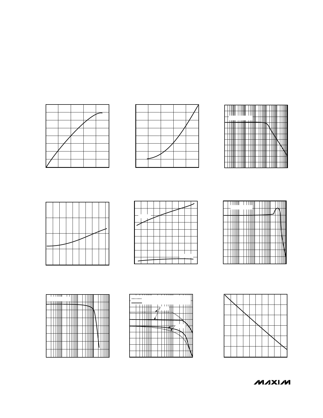
80
0
10
1k
100k
MAX504
AMPLIFIER SIGNAL-TO-NOISE RATIO
10
MAX504-7
FREQUENCY (Hz)
SIGNAL-TO-NOISE RATIO (dB)
20
40
60
30
50
70
10k
100
REFIN = 4Vp-p
20
-30
1
MAX504
GAIN AND PHASE vs.FREQUENCY
-10
10
MAX504-8
FREQUENCY (kHz)
GAIN (dB)
10
100
0
-20
800
-180
0
180
GAIN
PHASE
RFB CONNECTED TO AGND (G=2)
RFB CONNECTED TO VOUT (G=1)
PHASE (degrees)
2.0520
2.0490
0
5.0
MAX504 REFERENCE OUTPUT VOLTAGE
vs. REFERENCE LOAD CURRENT
2.0495
2.0515
MAX504-9
REFERENCE LOAD CURRENT (mA)
REFERENCE OUTPUT VOLTAGE (V)
3.0
2.0505
2.0500
1.0
2.0
4.0
2.0510
0.5
1.5
2.5
3.5
4.5
4
-14
1
100
100k
MAX504
GAIN vs. FREQUENCY
-12
MAX504-6
FREQUENCY (Hz)
GAIN (dB)
-8
-4
0
2
-2
-6
-10
1k
10k
REFIN = 4Vp-p
120
-60
120
SUPPLY CURRENT vs.
TEMPERATURE
140
MAX504-5
TEMPERATURE (
°
C)
SUPPLY CURRENT (
µ
A)
60
240
180
-20
20
80
300
-40
0
40
100
140
280
260
220
200
160
MAX515
MAX504
2.055
2.045
-60
120
MAX504
REFERENCE VOLTAGE vs.
TEMPERATURE
MAX504-4
TEMPERATURE (
°
C)
REFERENCE VOLTAGE (V)
60
2.050
-20
20
80 100
40
0
-40
12
0
0
0.8
OUTPUT SINK CAPABILITY vs.
OUTPUT PULL-DOWN VOLTAGE
2
10
MAX504-1
OUTPUT PULL-DOWN VOLTAGE (V)
OUTPUT SINK CAPABILITY (mA)
0.6
6
4
0.2
0.4
8
1.0
14
16
2
8
V
DD
-5
V
DD
-1
OUTPUT SOURCE CAPABILITY vs.
OUTPUT PULL-UP VOLTAGE
7
3
MAX504-2
OUTPUT PULL-UP VOLTAGE (V)
OUTPUT SOURCE CAPABILITY (mA)
V
DD
-2
5
6
V
DD
-4
V
DD
-3
4
V
DD
-0
1
0
-110
0
1
10
1k
100k
ANALOG FEEDTHROUGH vs.
FREQUENCY
-30
-70
MAX504-3
FREQUENCY (Hz)
ANALOG FEEDTHROUGH (dB)
100
10k
1M
-100
-90
-80
-60
-50
-40
-20
-10
CODE = all 0s
__________________________________________Typical Operating Characteristics
(V
DD
= +5V, V
REFIN
= 2.048V, T
A
= +25°C, unless otherwise noted.)
MAX504/MAX515
5V, Low-Power, Voltage-Output,
Serial 10-Bit DACs
_______________________________________________________________________________________
7
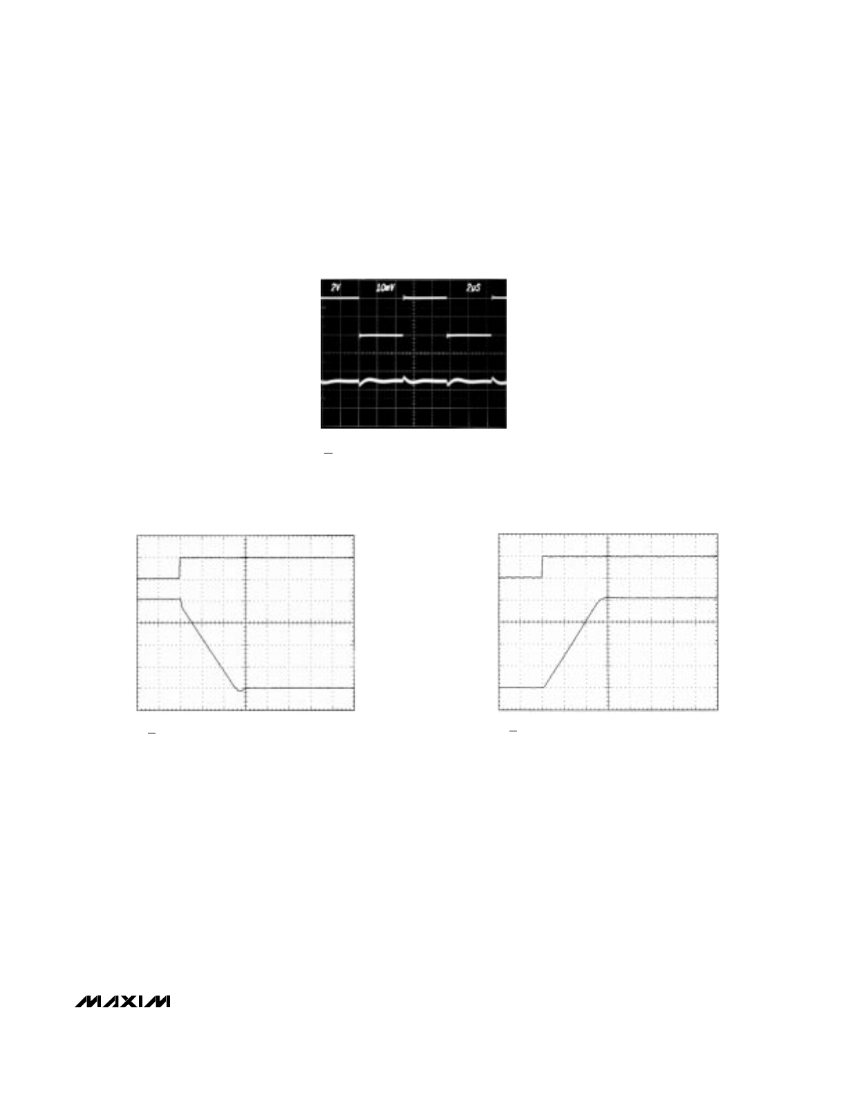
____________________________Typical Operating Characteristics (continued)
(VDD = +5V, VREFIN = 2.048V, TA = +25°C, unless otherwise noted.)
A: CS RISING EDGE, 5V/div
B: VOUT, NO LOAD, 1V/div
DUAL SUPPLY ±5V
BIPOLAR CONFIGURATION
V
REFIN
= 2V
A
B
NEGATIVE SETTLING TIME (MAX504)
5
µ
s/div
DIGITAL FEEDTHROUGH
A
B
CS = HIGH
A: DIN = 4Vp-p, 100kHz
B: VOUT, 10mV/div
2
µ
s/div
A: CS RISING EDGE, 5V/div
B: VOUT, NO LOAD, 1V/div
DUAL SUPPLY ±5V
BIPOLAR CONFIGURATION
V
REFIN
= 2V
A
B
POSITIVE SETTLING TIME (MAX504)
5
µ
s/div
MAX504/MAX515
5V, Low-Power, Voltage-Output
Serial 10-Bit DACs
8
_______________________________________________________________________________________
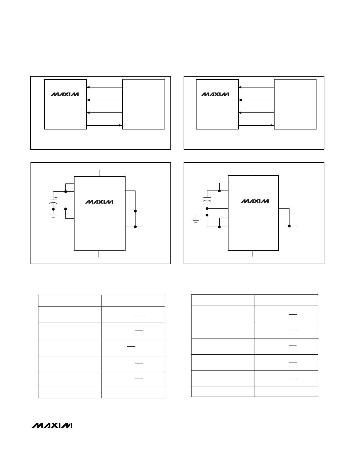
10
FUNCTION
1
BIPOFF
Bipolar offset/gain
resistor
2
DIN
Serial data input
3
CLR
Clear. Asynchronously sets
DAC register to all 0s.
PIN
—
1
4
SCLK
Serial clock input
5
CS
Chip select, active low
6
DOUT
Serial data output for
daisy-chaining
7
DGND
Digital ground
—
2
3
8
AGND
Analog ground
9
REFIN
Reference input
4
—
5
6
—
REFOUT
Reference output,
2.048V. Connect to V
DD
if not used.
11
—
V
SS
Negative power supply
12
7
VOUT
DAC output
13
8
V
DD
Positive power supply
14
—
RFB
Feedback resistor
MAX504
MAX515
NAME
____________________Pin Description
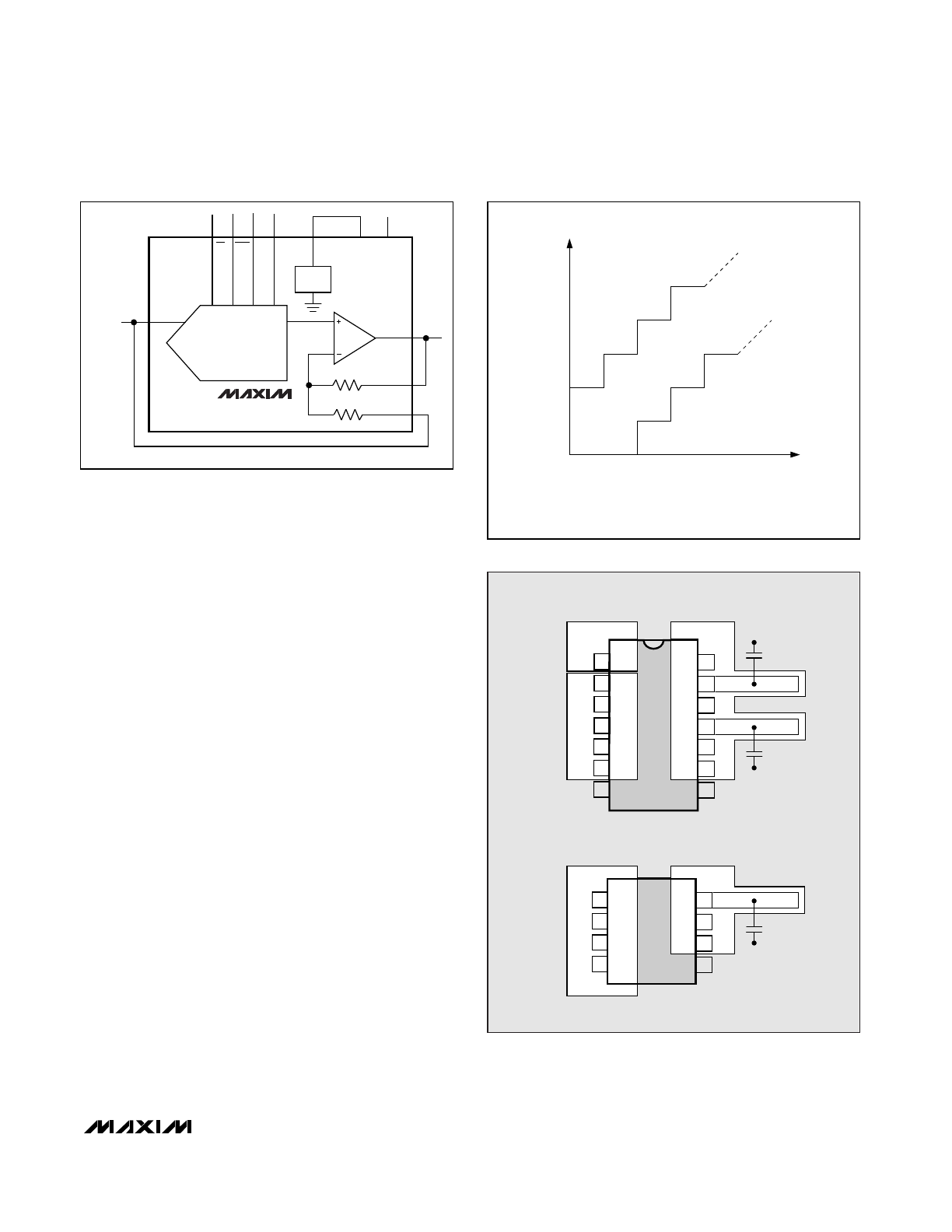
_______________Detailed Description
General DAC Discussion
The MAX504/MAX515 use an “inverted” R-2R ladder net-
work with a single-supply CMOS op amp to convert 10-bit
digital data to analog voltage levels (see
Functional
Diagram). The term “inverted” describes the ladder net-
work because the REFIN pin in current-output DACs is the
summing junction, or virtual ground, of an op amp.
However, such use would result in the output voltage
being the inverse of the reference voltage. The
MAX504/MAX515’s topology makes the output the same
polarity as the reference input.
An internal reset circuit forces the DAC register to reset
to all 0s on power-up. Additionally, a clear (CLR) pin,
when held low, sets the DAC register to all 0s. CLR
operates asynchronously and independently from the
chip select (CS) pin.
Buffer Amplifier
The output buffer is a unity-gain stable, rail-to-rail output,
BiCMOS op amp. Input offset voltage and CMRR are
trimmed to achieve better than 10-bit performance.
Settling time is 25µs to 0.01% of final value. The output is
short-circuit protected and can drive a 2k
Ω
load with more
than 100pF load capacitance.
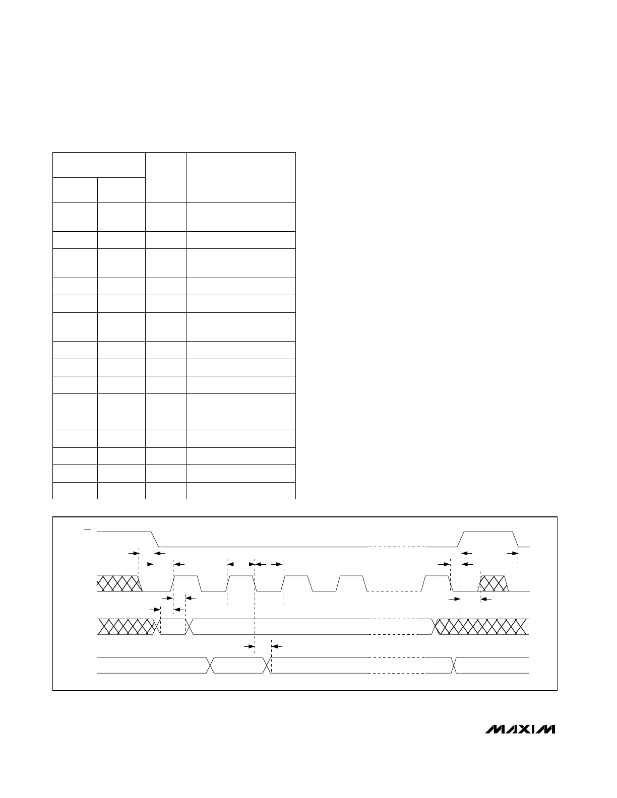
t
CSH0
t
CSS
t
CH
t
CL
t
CSH1
t
CSW
t
DS
t
DH
t
DO
CS
SCLK
DIN
DOUT
t
CS1
Figure 1. Timing Diagram
Internal Reference (MAX504 only)
The on-chip reference is laser trimmed to generate 2.048V
at REFOUT. The output stage can source and sink current
so REFOUT can settle to the correct voltage quickly in
response to code-dependent loading changes. Typically,
source current is 5mA and sink current is 100µA.
REFOUT connects the internal reference to the R-2R DAC
ladder at REFIN. The R-2R ladder draws 50µA maximum
load current. If any other connection is made to REFOUT,
ensure that the total load current is less than 100µA to
avoid gain errors.
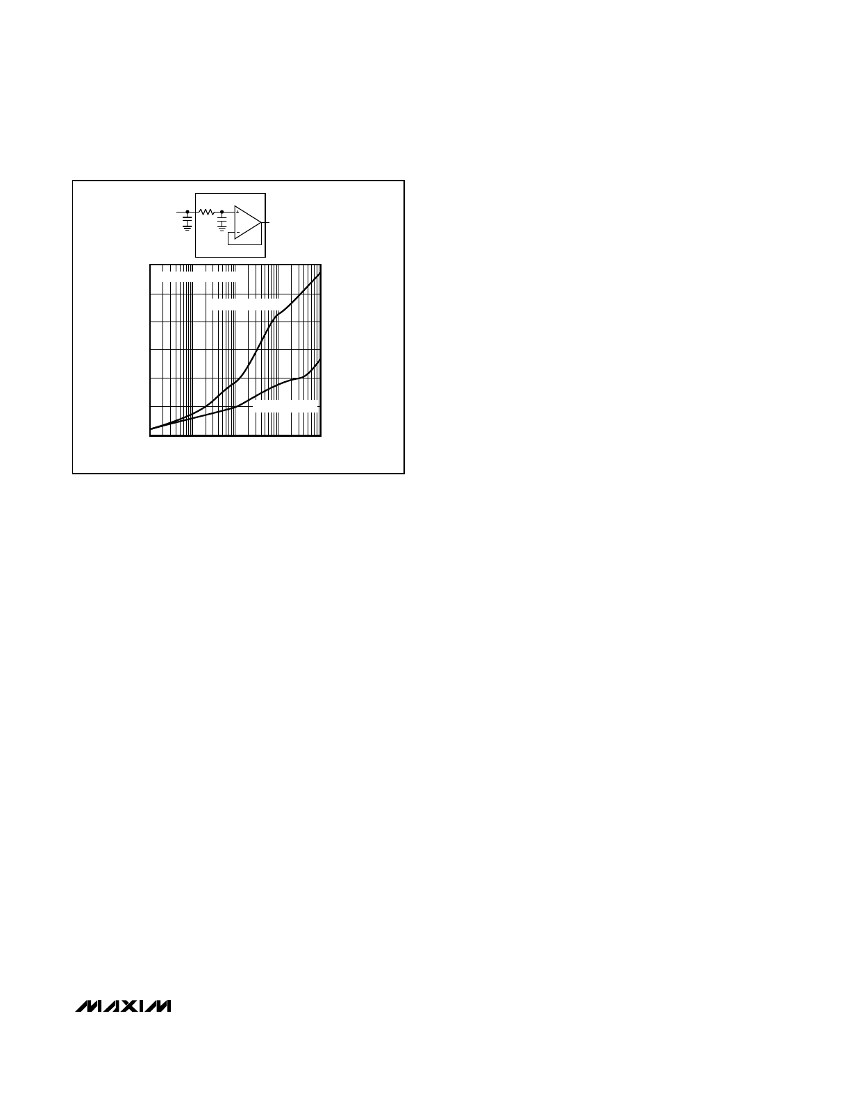
For applications requiring very low-noise performance, con-
nect a 33µF capacitor from REFOUT to AGND. If noise is
not a concern, a lower value (3.3µF min) capacitor may be
used. To reduce noise further, insert a buffered RC filter
between REFOUT and REFIN (Figure 2). The reference
bypass capacitor C
REFOUT
is still required for reference sta-
bility. In applications not requiring the reference, connect
REFOUT to V
DD
(to save power and to eliminate the need
for C
REFOUT
) or use the MAX515 (no internal reference).
External Reference
An external reference in the range (V
SS
+ 2V) to (V
DD
- 2V)
may be used with the MAX504 in dual-supply operation.
With the MAX515 or the MAX504 in single-supply use, the
reference must be positive and may not exceed V
DD
- 2V.
The reference voltage determines the DAC’s full-scale out-
put. The DAC input resistance is code dependent and is
minimum (40k
Ω
) at code 0101... and virtually infinite at
code 0000.... REFIN’s input capacitance is also code
dependent and has a 50pF maximum value at several
codes.
If an upgrade to the internal reference is required, the 2.5V
MAX873A is suitable: ±15mV initial accuracy, TCV
OUT
=
7ppm/°C (max).
Logic Interface
The MAX504/MAX515 logic inputs are designed to be
compatible with TTL or CMOS logic levels. However, to
achieve the lowest power dissipation, drive the digital
inputs with rail-to-rail CMOS logic. With TTL logic levels,
the power requirement increases by a factor of approxi-
mately 2.
Serial Clock and Update Rate
Figure 1 shows the MAX504/MAX515 timing. The maxi-
mum serial clock rate is given by 1/(t
CH
+t
CL
), approxi-
mately 14MHz. The digital update rate is limited by the
chip-select period, which is 16 x (t
CH
+ t
CL
) + t
CSW
.
This equals a 1.14µs, or 877kHz, update rate. However,
the DAC settling time to 10 bits is 25µs, which may limit
the update rate to 40kHz for full-scale step transitions.
____________Applications Information
Refer to Figures 3a and 3b for typical operating con-
nections.
Serial Interface
The MAX504/MAX515 use a three-wire serial interface that
is compatible with SPI™, QSPI™ (CPOL = CPHA = 0), and
Microwire™ standards as shown in Figures 4 and 5. The
DAC is programmed by writing two 8-bit words (see Figure
1 and the
Functional Diagram). 16 bits of serial data are
clocked into the DAC in the following order: 4 fill (dummy)
bits, 10 data bits, and 2 sub-LSB 0s. The 4 dummy bits are
not normally needed, and are required
only
when DACs
are daisy chained. The 2 sub-LSB 0s, however, are
always
needed, and allow hardware and software compatibility
with the 12-bit MAX531/MAX538/MAX539. Transitions at
CS should occur while SCLK is low. Data is clocked in on
SCLK’s rising edge while CS is low. The serial input data is
held in a 16-bit serial shift register. On CS’s rising edge, the
10 data-bits are transferred to the DAC register and update
the DAC. With CS high, data cannot be clocked into the
MAX504/MAX514.
The MAX504/MAX515 inputs data in 16-bit blocks. The SPI
and Microwire interfaces output data in 8-bit blocks, there-
by requiring two write cycles to input data to the DAC. The
QSPI interface allows variable data input from 8 to 16 bits,
and can be loaded into the DAC in one write cycle.
MAX504/MAX515
5V, Low-Power, Voltage-Output,
Serial 10-Bit DACs
_______________________________________________________________________________________
9
300
50
1
10
100
100
MAX504-FIG02
FREQUENCY (kHz)
REFERENCE NOISE (
µ
V
RMS
)
150
200
250
0
0.1
1000
TOTAL
REFERENCE
NOISE
R
S
REFOUT
C
REFOUT
C
S
TEK 7A22
C
REFOUT
= 3.3
µ
F
C
REFOUT
= 47
µ
F
SINGLE POLE ROLLOFF
1.8
1.6
1.4
1.2
1.0
0.8
0.6
0.4
0.2
0.0
REFERENCE NOISE (mVp-p)
Figure 2. Reference Noise vs. Frequency
SPI and QSPI are trademarks of Motorola, Inc. Microwire is a trademark of National Semiconductor Corp.
MAX504/MAX515
Daisy-Chaining Devices
The serial output, DOUT, allows cascading of two or more
DACs. The data at DIN appears at DOUT, delayed by 16
clock cycles plus one clock width. For low power, DOUT is
a CMOS output that does not require an external pull-up
resistor. DOUT does
not
go into a high-impedance state
when CS is high. DOUT changes on SCLK’s falling edge
when CS is low. When CS is high, DOUT remains in the
state of the last data bit.
Any number of MAX504/MAX515 DACs can be daisy-
chained by connecting the DOUT of one device to the DIN
of the next device in the chain. For proper timing, ensure
that t
CL
(SCLK low) is greater than t
DO
+ t
DS
.
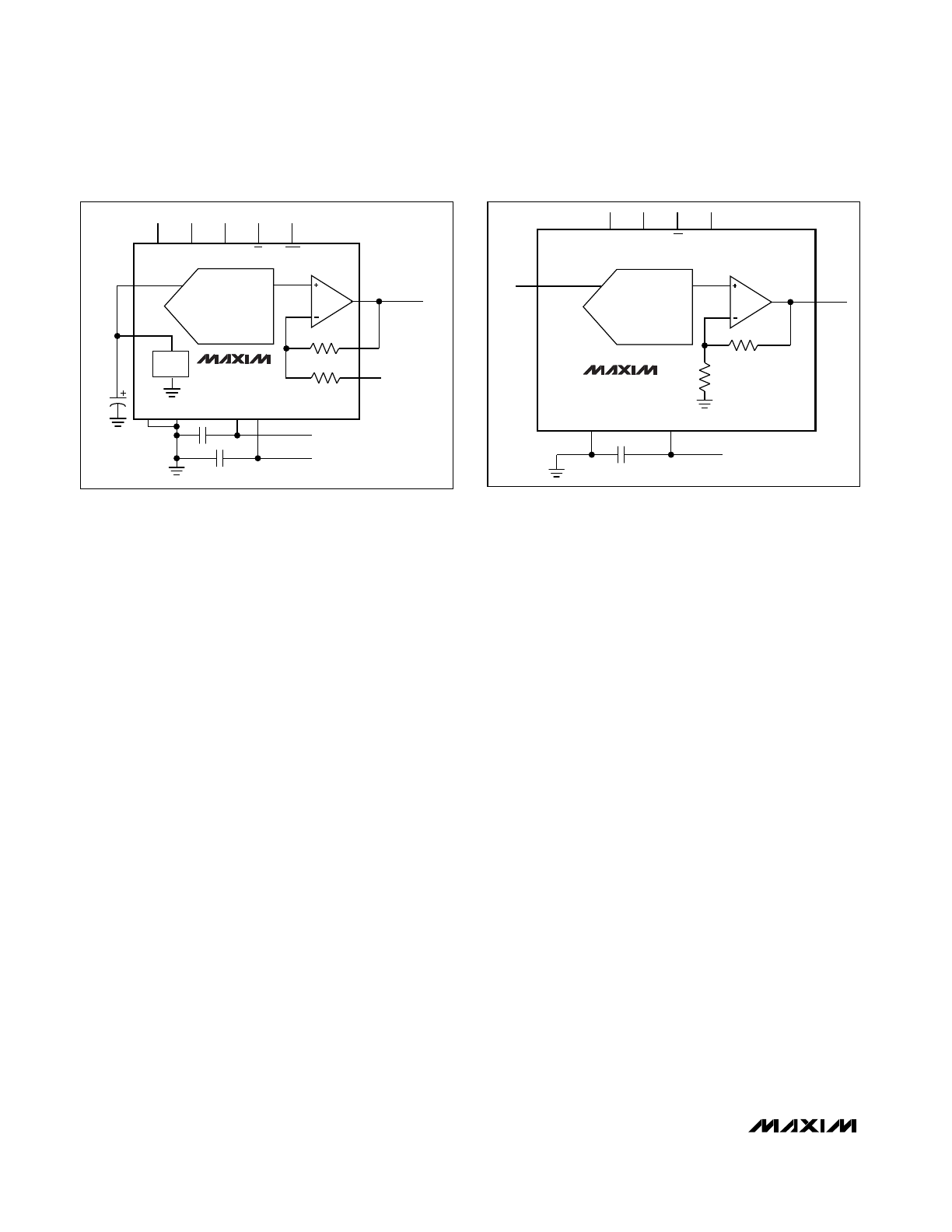
Unipolar Configuration
The MAX504 is configured for a gain of 1 (0V to V
REFIN
unipolar output) by connecting BIPOFF and RFB to VOUT
(Figure 6). The converter operates from either single or
dual supplies in this configuration. See Table 1 for the
DAC-latch contents (input) vs. the analog VOUT (output).
In this range, 1LSB = V
REFIN
(2
-10
), where V
REF
is the
voltage on REFIN.
A gain of 2 (0V to 2V
REFIN
unipolar output) is set up by
connecting BIPOFF to AGND and RFB to VOUT (Figure
7). Table 2 shows the DAC-latch contents vs. VOUT. The
MAX504 operates from either single or dual supplies in
this mode. In this range,
1LSB = (2)(V
REFIN
)(2
-10
) = (V
REFIN
)(2
-9
).
The MAX515 is internally configured for unipolar gain of
2 operation.
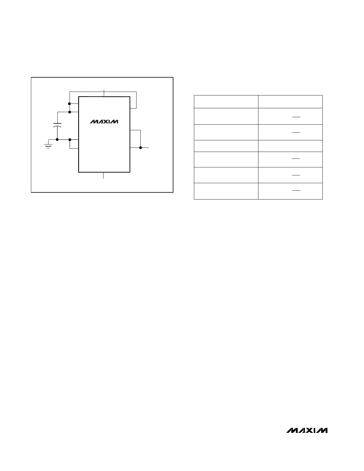
Bipolar Configuration
A bipolar range is set up by connecting BIPOFF to
REFIN and RFB to VOUT, and operating from dual
(±5V) supplies (Figure 8). Table 3 shows the DAC-latch
contents (input) vs. VOUT (output). In this range,
1LSB = V
REFIN
(2
-9
).
Four-Quadrant Multiplication
The MAX504 can be used as a four-quadrant multiplier
by connecting BIPOFF to REFIN and RFB to VOUT, and
using (1) an offset binary digital code, (2) bipolar power
supplies, and (3) a bipolar analog input at REFIN within
the range V
SS
+ 2V to V
DD
- 2V, as shown in Figure 9.
In general, a 10-bit DAC’s output is (D)(V
REFIN)
(G),
where “G” is the gain (1 or 2) and “D” is the binary rep-
resentation of the digital input divided by 2
10
or 1,024.
This formula is precise for unipolar operation. However,
for bipolar, offset binary operation, the MSB is really a
polarity bit. No resolution is lost because the number of
steps is the same. The output voltage, however, has
been shifted from a range of, for example, 0V to 4.096V
(G = 2) to a range of -2.048V to +2.048V.
Keep in mind that when using the DAC as a four-quad-
rant multiplier, the scale is skewed. Negative full scale
is -V
REFIN
, while positive full scale is +V
REFIN
- 1LSB.
5V, Low-Power, Voltage-Output,
Serial 10-Bit DACs
10
______________________________________________________________________________________
MAX504
CONNECT BIPOFF
TO VOUT FOR G=1,
TO AGND FOR G=2,
OR TO REFIN FOR
BIPOLAR GAIN
INVERTED
R-2R DAC
DIN
DOUT
SCLK
CS
CLR
2.048V
REFIN
REFOUT
AGND DGND
V
DD
V
SS
33
µ
F
0.1
µ
F
0.1
µ
F
2R
2R
BIPOFF
RFB
VOUT
+5V
0V to -5V
MAX515
INVERTED
R-2R DAC
DIN
DOUT
SCLK
CS
REFIN
AGND
V
DD
VOUT
MAX515
ONLY
0.1
µ
F
2R
2R
+5V
Figure 3a. MAX504 Typical Operating Circuit
Figure 3b. MAX515 Typical Operating Circuit
MAX504/MAX515
5V, Low-Power, Voltage-Output,
Serial 10-Bit DACs
______________________________________________________________________________________
11
MAX504
MAX515
MICROWIRE
PORT
SCLK
DIN
CS
DOUT
SK
SO
I/O
SI
THE DOUT-SI CONNECTION IS NOT REQUIRED FOR WRITING TO THE
MAX504/MAX515, BUT MAY BE USED FOR VERIFYING DATA TRANSFER .
MAX504
MAX515
SPI
PORT
SCLK
DIN
CS
DOUT
SCK
MOSI
I/O
MISO
THE DOUT-MISO CONNECTION IS NOT REQUIRED FOR WRITING TO THE
MAX504/MAX515, BUT MAY BE USED FOR VERIFYING DATA TRANSFER .
CPOL = 0, CPHA = 0
Figure 4. Microwire Connection
Figure 5. SPI/QSPI Connection
Figure 6. Unipolar Configuration (0V to +2.048V Output)
33µF
REFIN
REFOUT
AGND
DGND
V
DD
V
SS
BIPOFF
RFB
VOUT
V
OUT
0V TO -5V
+5V
G = 1
MAX504
33µF
REFIN
REFOUT
AGND
DGND
V
DD
V
SS
BIPOFF
RFB
VOUT
V
OUT
0V TO -5V
+5V
G = 2
MAX504
Figure 7. Unipolar Configuration (0V to +4.096V Output)
Table 2. Unipolar Binary Code Table
(0V to 2V
REFIN
Output), Gain = 2
Table 1. Unipolar Binary Code Table
(0V to V
REFIN
Output), Gain = 1
INPUT*
OUTPUT
1111
1111
11(00)
1000
0000
01(00)
1000
0000
00(00)
0111
1111
11(00)
0000
0000
01(00)
0000
0000
00(00)
(V
REFIN
)
1023
1024
(V
REFIN
)
513
1024
(V
REFIN
)
512
1024
(V
REFIN
)
511
1024
(V
REFIN
)
1
1024
OV
= +V
REFIN
/2
INPUT*
OUTPUT
1111
1111
11(00)
1000
0000
01(00)
1000
0000
00(00)
0111
1111
11(00)
0000
0000
01(00)
0000
0000
00(00)
+2 (V
REFIN
)
1023
1024
+2 (V
REFIN
)
513
1024
+2 (V
REFIN
)
512
1024
+2 (V
REFIN
)
511
1024
+2 (V
REFIN
)
1
1024
OV
= +V
REFIN
*
Write 10-bit data words with two sub-LSB 0s because the
DAC input latch is 12 bits wide.
*
Write 10-bit data words with two sub-LSB 0s because the
DAC input latch is 12 bits wide.
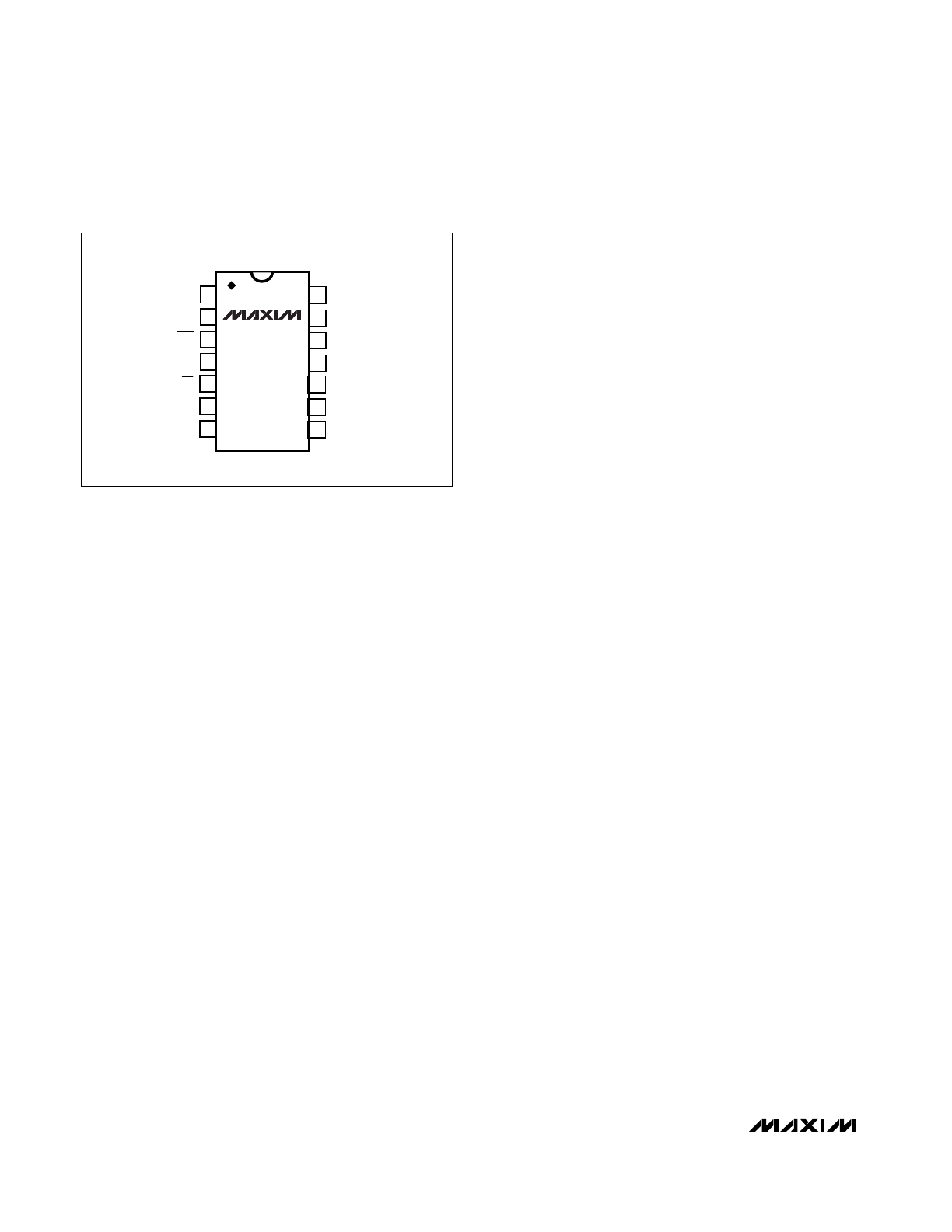
MAX504/MAX515
Single-Supply Linearity
As with any amplifier, the MAX504/MAX515’s output
buffer offset can be positive or negative. When the off-
set is positive, it is easily accounted for (Figure 10).
However, when the offset is negative, the buffer output
cannot follow linearly when there is no negative supply.
In that case, the amplifier output (VOUT) remains at
ground until the DAC voltage is sufficient to overcome
the offset and the output becomes positive.
Normally, linearity is measured after accounting for
zero error and gain error. Since, in single-supply opera-
tion, the actual value of a negative offset is unknown, it
cannot be accounted for during test. Additionally, the
output buffer amplifier exhibits a nonlinearity near-zero
output when operating with a single supply. To account
for this nonlinearity in the MAX504/MAX515, linearity
and gain error are measured from code 3 to code
1023. The output buffer’s offset and nonlinearity do not
affect monotonicity, and these DACs are guaranteed
monotonic starting with code zero. In dual-supply oper-
ation, linearity and gain error are measured from code
0 to 1023.
Power-Supply Bypassing and
Ground Management
Best system performance is obtained with printed cir-
cuit boards that use separate analog and digital
ground planes. Wire-wrap boards are not recommend-
ed. The two ground planes should be connected
together at the low-impedance power-supply source.
DGND and AGND should be connected together at the
chip. For the MAX504 in single-supply applications,
connect V
SS
to AGND at the chip. The best ground
connection may be achieved by connecting the DAC's
DGND and AGND pins together and connecting that
point to the system analog ground plane. If the DAC's
DGND is connected to the system digital ground, digi-
tal noise may get through to the DAC’s analog portion.
Bypass V
DD
(and V
SS
in dual-supply mode) with a
0.1µF ceramic capacitor connected between V
DD
and
AGND (and between V
SS
and AGND). Mount it with
short leads close to the device. Ferrite beads may also
be used to further isolate the analog and digital power
supplies.
Figures 11a and 11b illustrate the grounding and
bypassing scheme described.
Saving Power
When the DAC is not being used by the system, mini-
mize power consumption by setting the appropriate
code to minimize load current. For example, in bipolar
mode, with a resistive load to ground, set the DAC
code to mid-scale (see Table 3). If there is no output
load, minimize internal loading on the reference by set-
ting the DAC to all 0s (on the MAX504, use CLR).
Under this condition, REFIN is high impedance and the
op amp operates at its minimum quiescent current.
Due to these low currents, the output settling time for a
zero input code typically increases to 60µs (100µs
max).
5V, Low-Power, Voltage-Output,
Serial 10-Bit DACs
12
______________________________________________________________________________________
Figure 8. Bipolar Configuration (-2.048V to +2.048V Output)
Table 3. Bipolar (Offset Binary) Code
Table (-V
REFIN
to +V
REFIN
Output)
33µF
REFIN
REFOUT
AGND
DGND
BIPOFF
RFB
VOUT
V
OUT
-5V
+5V
MAX504
INPUT*
OUTPUT
1111
1111
11(00)
1000
0000
01(00)
1000
0000
00(00)
0111
1111
11(00)
0000
0000
01(00)
0000
0000
00(00)
(+V
REFIN
)
511
512
(+V
REFIN
)
1
512
(-V
REFIN
)
1
512
(-V
REFIN
)
511
512
0V
(-V
REFIN
)
512
512
= -V
REFIN
*
Write 10-bit data words with two sub-LSB 0s because the
DAC input latch is 12 bits wide.
AC Considerations
Digital Feedthrough
High-speed serial data at any of the digital input or output
pins may couple through the DAC package and cause
internal stray capacitance to appear at the DAC output as
noise, even though CS is held high (see
Typical Operating
Characteristics). This digital feedthrough is tested by hold-
ing CS high transmitting 0101... from DIN to DOUT.
Analog Feedthrough
Because of internal stray capacitance, higher frequency
analog input signals may couple to the output as shown in
the Analog Feedthrough vs. Frequency graph in the
Typical Operating Characteristics. It is tested by holding
CS high, setting the DAC code to all 0s, and sweeping
REFIN.
MAX504/MAX515
5V, Low-Power, Voltage-Output,
Serial 10-Bit DACs
______________________________________________________________________________________
13
MAX504
INVERTED
R-2R DAC
DIN DOUT
SIGNAL
IN
2.048V
REFIN
V
DD
V
SS
2R
2R
CS CLR
BIPOFF
RFB
VOUT
REFOUT
Figure 9. MAX504 Connected as Four-Quadrant Multiplier. The
unused REFOUT is connected to V
DD
.
1
2
3
4
5
1
2
3
4
5
0
POSITIVE OFFSET
NEGATIVE OFFSET
DAC CODE (LSBs)
OUTPUT (LSBs)
Figure 10. Single-Supply Offset
8
10
9
14
13
12
11
5
6
2
3
4
7
1
8
7
6
5
1
2
3
4
0.1
µ
F
(b) MAX515 BYPASSING
(a) MAX504 BYPASSING
ANALOG GROUND PLANE
0.1
µ
F
0.1
µ
F
Figure 11. Power-Supply Bypassing
MAX504/MAX515
5V, Low-Power, Voltage-Output,
Serial 10-Bit DACs
14
______________________________________________________________________________________
____Pin Configurations (continued)
1
2
3
4
14
13
12
11
RFB
V
DD
VOUT
V
SS
SCLK
CLR
DIN
BIPOFF
DIP/SO
TOP VIEW
MAX504
5
6
7
10
9
8
REFOUT
REFIN
AGND
DGND
DOUT
CS
___________________Chip Information
TRANSISTOR COUNT: 922
MAX504/MAX515
5V, Low-Power, Voltage-Output,
Serial 10-Bit DACs
______________________________________________________________________________________
15
________________________________________________________Package Information
SOICN.EPS
MAX504/MAX515
5V, Low-Power, Voltage-Output,
Serial 10-Bit DACs
Maxim cannot assume responsibility for use of any circuitry other than circuitry entirely embodied in a Maxim product. No circuit patent licenses are
implied. Maxim reserves the right to change the circuitry and specifications without notice at any time.
16
____________________Maxim Integrated Products, 120 San Gabriel Drive, Sunnyvale, CA 94086 408-737-7600
© 1997 Maxim Integrated Products
Printed USA
is a registered trademark of Maxim Integrated Products.
___________________________________________Package Information (continued)
PDIPN.EPS