
_______________General Description
The MAX2003/MAX2003A are fast-charge battery charg-
ers (with conditioning) for NiCd (nickel cadmium) or
NiMH (nickel-metal hydride) rechargeable batteries. The
MAX2003A has the same features as the MAX2003 with
an additional pulsed trickle-charge mode to prevent den-
drite formation in NiMH batteries. Each can be config-
ured as a switch-mode current regulator or as a gating
controller for an external current source. Switch-mode
current regulation provides efficient energy transfer,
reducing power dissipation and the associated heating.
Gating control of an external current source requires
minimal components, saving space and cost.
On-chip algorithms determine charge termination, so the
MAX2003/MAX2003A can be used as stand-alone
chargers. Fast-charge termination is accomplished by
five methods: temperature slope, negative voltage
change, maximum temperature, maximum time, and
maximum voltage. As a safety feature, the start of fast-
charge is inhibited until battery voltage and temperature
are within safe limits. By selecting the appropriate
charge-termination method, a single circuit can be built
with the MAX2003/MAX2003A to fast-charge both NiMH
and NiCd batteries.
The MAX2003/MAX2003A provide a switch-activated
discharge-before-charge option that allows for battery
conditioning and more accurate capacity measure-
ment. Other features include optional top-off charging
and direct drivers for LED status lights.
The MAX2003, in DIP and wide SO packages, is a direct
plug-in replacement for the bq2003. The MAX2003/
MAX2003A also come in a space-saving narrow SO
package. The MAX2003A evaluation kit (MAX2003A
EVKIT-SO) is available to assist in designs.
________________________Applications
Battery-Powered Equipment:
Laptop, Notebook, and Palmtop Computers
Handy-Terminals
Portable Consumer Products:
Portable Stereos
Cordless Phones
Backup-Battery Applications:
Memory Hold-Up
Emergency Switchovers
____________________________Features
♦
Stand-Alone NiCd or NiMH Fast Chargers
♦
New Pulsed Trickle-Charge Mode (MAX2003A only)
♦
Provide Switch-Mode, Gated, or Linear Control
Regulation
♦
Small, Narrow SOIC Package Available
♦
On-Chip Fast-Charge Termination Methods:
• Temperature Slope
• Maximum Voltage
• Negative Delta Voltage
• Maximum Time
• Maximum Temperature
♦
Automatically Switch from Fast-Charge to
Trickle-Charge or Top-Off Charge
♦
Optional Discharge-Before-Charge
♦
Directly Drive Status LEDs
♦
Optional Top-Off Charge
MAX2003/MAX2003A
NiCd/NiMH Battery Fast-Charge Controllers
________________________________________________________________
Maxim Integrated Products
1
Call toll free 1-800-998-8800 for free samples or literature.
19-0371; Rev 1; 7/95
PART
MAX2003
CPE
MAX2003CSE
0°C to +70°C
0°C to +70°C
TEMP. RANGE
PIN-PACKAGE
16 Plastic DIP
16 Narrow SO
__________________Pin Configuration
16
15
14
13
12
11
10
9
1
2
3
4
5
6
7
8
V
CC
DIS
MOD
CHG
TM1
DVEN
DCMD
CCMD
TOP VIEW
MAX2003
MAX2003A
TEMP
MCV
TCO
SNS
V
SS
BAT
TS
TM2
DIP/SO
MAX2003CWE
MAX2003C/D
0°C to +70°C
0°C to +70°C
16 Wide SO
Dice*
* Contact factory for dice specifications.
EVALUATION KIT MANUAL
FOLLOWS DATA SHEET
MAX2003A
CPE
MAX2003ACSE
MAX2003ACWE
MAX2003AC/D
0°C to +70°C
0°C to +70°C
16 Plastic DIP
16 Narrow SO
0°C to +70°C
0°C to +70°C
16 Wide SO
Dice*
______________Ordering Information
MAX2003/MAX2003A
NiCd/NiMH Battery Fast-Charge Controllers
2
_______________________________________________________________________________________
ABSOLUTE MAXIMUM RATINGS
ELECTRICAL CHARACTERISTICS
(V
CC
= 4.5V to 5.5V, Figure 1, all measurements are with respect to V
SS
, T
A
= T
MIN
to T
MAX
, unless otherwise noted.)
Stresses beyond those listed under “Absolute Maximum Ratings” may cause permanent damage to the device. These are stress ratings only, and functional
operation of the device at these or any other conditions beyond those indicated in the operational sections of the specifications is not implied. Exposure to
absolute maximum rating conditions for extended periods may affect device reliability.
All Pins to V
SS
...........................................................-0.3V, +6.0V
Continuous Power Dissipation (T
A
= +70°C)
Plastic DIP (derate 10.53mW/°C above +70°C) ...........842mW
Narrow SO (derate 8.70mW/°C above +70°C) .............696mW
Wide SO (derate 9.52mW/°C above +70°C).................762mW
Operating Temperature Range...............................0°C to +70°C
Storage Temperature Range .............................-65°C to +150°C
Lead Temperature (soldering, 10sec) .............................+300°C
V
BAT
- V
SNS
No load
For DIS, TEMP and CHG,
0mA
≤
I
LOAD
≤
5mA; For MOD,
0mA
≤
I
LOAD
≤
10mA
V
CC
= 5V
V
CC
= 5V, V
TCO
= 1.4V
V
CC
= 5V
V
CC
= 5V
V
CC
= 5V
V
CC
= 5V
V
TS
- V
SNS
V
CC
= 5V
V
CC
= 5V
CONDITIONS
V
0.5
V
OL
Logic-Low Threshold
mV
16
V
THERM
Thermistor Input Resolution
(Note 2)
mV
12
-
∆
V
Negative Delta Voltage
(Note 2)
mV
30
V
SNSHI -
V
SNSLO
Delta Sense Voltage
(Note 1)
V
0.044V
CC
- 25mV
0.044V
CC
+ 25mV
0.044V
CC
V
SNSLO
Sense Trip Threshold Low
V
0.05V
CC
- 25mV
0.05V
CC
+ 25mV
0.05V
CC
V
SNSHI
Sense Trip Threshold High
V
0.0
V
CC
V
CELL
Cell Potential
mA
0.75
2.2
I
CC
V
4.5
5.0
5.5
V
CC
Supply Voltage
Supply Current
V
(V
LTF
/8) + (7V
TCO
/8) - 30mV
(V
LTF
/8) + 7V
TCO
/8
(V
LTF
/8) + (7V
TCO
/8) + 30mV
V
HTF
High-Temperature
Trip Threshold
V
V
LTF -
0.2V
CC
V
LTF
V
TCO
Temperature Cutoff Voltage
V
0.4V
CC
- 30mV
0.4V
CC
+ 30mV
0.4V
CC
V
LTF
Low-Temperature
Trip Threshold
V
V
EDV
V
EDV
+ 0.2V
CC
V
MCV
Maximum Cell Voltage
V
0.0
V
CC
V
BAT
Battery Voltage Input
V
0.0
V
CC
V
TEMP
Temperature Potential
V
0.0
V
CC
V
TS
Temperature Sense
Input Voltage
UNITS
MIN
TYP
MAX
SYMBOL
PARAMETER
For DIS, TEMP and CHG,
0mA
≤
I
LOAD
≤
5mA; For MOD,
0mA
≤
I
LOAD
≤
10mA
V
V
CC
- 0.5
V
OH
Logic-High Threshold
V
CC
= 5V
V
0.2V
CC
- 30mV
0.2V
CC
+ 30mV
0.2V
CC
V
EDV
End-of-Discharge Voltage
MAX2003/MAX2003A
NiCd/NiMH Battery Fast-Charge Controllers
_______________________________________________________________________________________
3
ELECTRICAL CHARACTERISTICS (continued)
(V
CC
= 4.5V to 5.5V, Figure 1, all measurements are with respect to V
SS
, T
A
= T
MIN
to T
MAX
, unless otherwise noted.)
TIMING CHARACTERISTICS
(V
CC
= 4.5V to 5.5V, Figure 1, all measurements are with respect to V
SS
, T
A
= T
MIN
to T
MAX
, unless otherwise noted. Typical values
are at V
CC
= 5.0V, T
A
= +25°C.)
Note 1:
The sense trip levels are determined by an internal resistor divider network that provides a typical difference of 30mV from
SNSHI to SNSLO. Slight variation in this delta is seen if there is a resistor mismatch in the network.
Note 2:
Typical variations of Negative Delta Voltage and Thermistor Input Resolution parameters are less than ±4mV.
Note 3:
Ratio of actual versus expected timeout (see Table 4). Tested with TM1 = TM2 = floating.
Note 4:
To recognize a battery insert signal, V
BAT
must be greater than V
MCV
for at least t
BTO
.
MOD pin in fast-charge mode, V
CC
= 5V
(Note 3)
CCMD, DCMD
CONDITIONS
kHz
100
f
MAX
MOD Switching Frequency
0.84
1.00
1.16
µs
1.0
t
MPW
Minimum Pulse Width
Variation of Fast-Charge Timeout
UNITS
MIN
TYP
MAX
SYMBOL
PARAMETER
CCMD, DCMD,
DVEN at V
CC
and V
SS
CCMD, DCMD, DVEN
CCMD, DCMD, DVEN
TM1, TM2 = V
CC
TM1, TM2 = V
SS
CONDITIONS
µA
-1.0
1.0
I
LKG
Input Logic Leakage
1.0
V
CC
- 1.0
V
IH
Input Logic Voltage High
µA
-70.0
I
IH
Input Logic Current High
µA
70.0
I
IL
Input Logic Current Low
UNITS
MIN
TYP
MAX
SYMBOL
PARAMETER
TM1, TM2 = tri-state
BAT, MCV, TCO, SNS, TS
µA
-2.0
2.0
I
IZ
Input Logic Current High-Z
M
Ω
50
Input Impedance
TM1, TM2
V
V
CC
- 0.3
TM1, TM2
V
0.3
V
IL
Input Logic Voltage Low
ms
200
250
300
t
BTO
Battery Replacement Timeout
(Note 4)
MAX2003/MAX2003A
NiCd/NiMH Battery Fast-Charge Controllers
4
_______________________________________________________________________________________
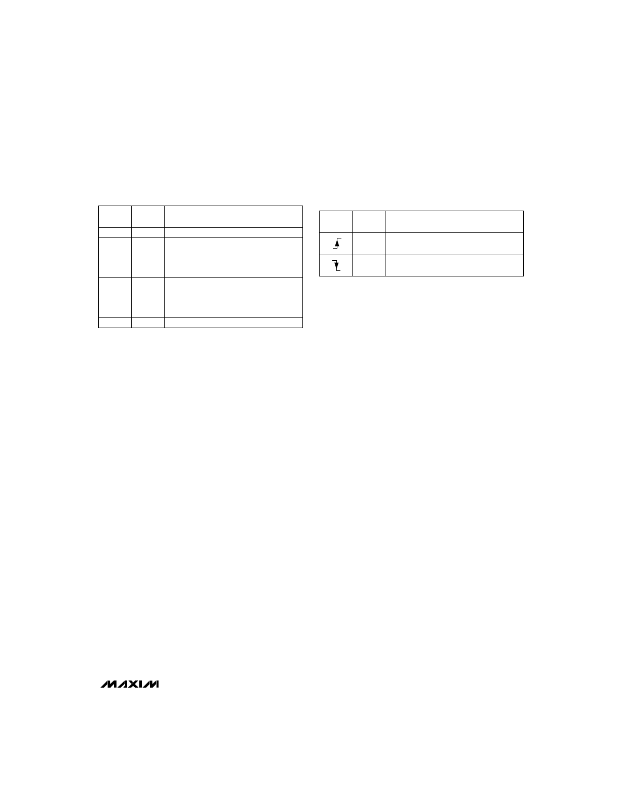
______________________________________________________________Pin Description
NAME
FUNCTION
1
CCMD
Charge-Enabled Mode Input—initiates fast-charge on a digital signal (see
Detailed Description for operating
conditions).
2
DCMD
Discharge-Enable Mode Input—initiates discharge-before-charge on a digital signal (see
Detailed
Description for operating conditions).
PIN
3
DVEN
Negative Delta Voltage (-
∆
V) Enable Input—enables -
∆
V charge-termination mode. If DVEN is high, the con-
troller uses negative-voltage change detection to terminate charge. If DVEN is low, this mode is disabled.
4, 5
TM1,
TM2
These inputs are used to program the fast-charge and hold-off times, and to enable the top-off charge
mode. The inputs can be high, low, or floating. See Table 4 for details.
9
SNS
Current-Sense Input—connected to the negative battery terminal. TS and BAT are referenced to this pin.
The voltage at SNS is directly proportional to the current through the battery and is used to determine how
and when MOD switches.
8
V
SS
Ground
7
BAT
Input Voltage of Single Battery Cell. If more than one cell is present, a resistor divider is needed to divide the
voltage down to a single cell voltage.
6
TS
Temperature Sense-Voltage Input from external thermistor. The thermistor temperature coefficient is nega-
tive, so the higher the temperature, the lower the voltage at this pin (See
Detailed Description for conditions
of operation).
14
MOD
Modulation Output. This push/pull output switches to enable or disable charging current. If MOD is high,
current is enabled. If it is low, current is disabled. For a 5V supply, if the voltage at the SNS pin is less than
220mV, MOD is high. If the voltage is above 250mV, MOD is low.
13
CHG
Charge Status Output. This push/pull LED driver indicates charge status (see
Detailed Description).
12
TEMP
Temperature Status Output. This push/pull LED driver indicates that the temperature is outside the accept-
able limits, and fast-charge and top-off are inhibited (see
Maximum Temperature Termination section in
Detailed Description).
11
MCV
Maximum Cell Voltage Input. If the voltage from BAT to SNS exceeds the voltage at MCV, fast or top-off
charging is terminated.
10
TCO
Temperature Cutoff-Voltage Input. If the voltage from TS to SNS is less than the voltage at TCO, a hot ther-
mistor (negative coefficient) is detected and fast or top-off charging is terminated.
16
V
CC
Power-Supply Voltage Input (+5V nominal)
15
DIS
Discharge-Switch Control Output. This push/pull output turns on the FET that discharges the battery.
MAX2003/MAX2003A
NiCd/NiMH Battery Fast-Charge Controllers
_______________________________________________________________________________________
5
MAX2003
MAX2003A
MOD
5
R1
60.4k
1k
100k
1k
R2
3.48k
R3
33.2k
14
14
16
13V/2A
DC SOURCE
R
TR
100k
(*150
Ω
(2W))
*TRICKLE-CHARGE
RATE
C/40
1N5822
1N5822
0.1
µ
F
15
6
9
7
7
1, 3, 5
2, 4, 6
10V ZENER
Q1
P
MMDF3P03HD
100
µ
H
1N5819
D
S
R
B1
100k
R
B2
20k
R
SNS
0.14
Ω
1%
(1W)
G
1700mAh
6 NiMH
R
DIS
4
Ω
(20W)
NTC
R
T
100k
R
B
100k
DISCHARGE
RATE
1C
CHARGE
RATE
1C
C
T
0.1
µ
F
0.1
µ
F
10k
C
B
0.1
µ
F
D
G
S
TO V
CC
R
T1
R
T2
DURACELL DR17
Q2
N
MMSF5NO3HD
* COMPONENT USED FOR MAX2003.
8, 10, 12
9, 11, 13
4
2
1
3
12
13
11
10
DIS
TS
SNS
BAT
V
SS
V
CC
V
CC
V
CC
TM2
PUSH TO
DISCHARGE
TM1
DCMD
TEMP
CHG
MCV
TC0
LED
LED
CCMD
DVEN
8
74HC04
LM317
243
Ω
22
µ
F
22
µ
F
22
µ
F
732
Ω
ADJ
5V OUT
IN
0.1
µ
F
0.1
µ
F
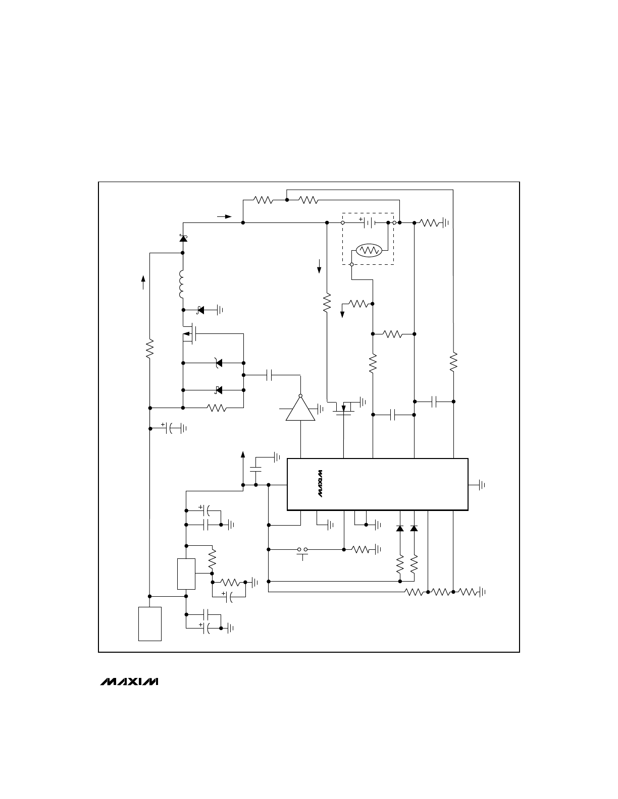
Figure 1. Switched-Mode Operation for NiMH Batteries with
∆
T/
∆
t Termination
MAX2003/MAX2003A
NiCd/NiMH Battery Fast-Charge Controllers
6
_______________________________________________________________________________________
_______________Detailed Description
The MAX2003/MAX2003A is a fast-charge battery charg-
er that uses several methods of charge termination. The
device constantly monitors your choice of the following
conditions to determine termination of fast-charge:
•
Negative Delta Voltage (-
∆
V)
•
Rate-of-Change of Temperature (
∆
T/
∆
t)
•
Maximum Voltage
•
Maximum Time
•
Maximum Temperature
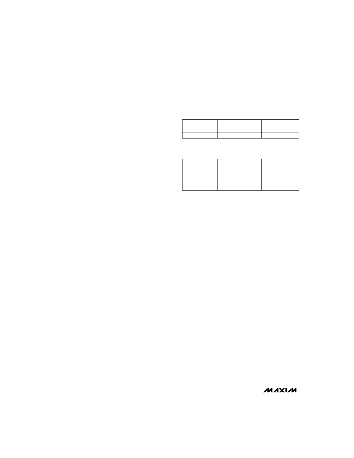
Figure 2 shows the block diagram for the MAX2003/
MAX2003A.
The first step in creating a fast-charge battery-charger
circuit is to determine what type of battery will be used
and what conditions the battery manufacturer recom-
mends for termination of fast-charge. The type of bat-
tery (NiCd or NiMH) and charge rate determine which
method(s) of termination should be used.
The charging characteristics of NiMH batteries are simi-
lar to those of NiCd batteries, but there are some key dif-
ferences that affect the choice of charge-termination
method. Since the type of charge termination can be dif-
ferent for NiCd and NiMH batteries, it may not always be
possible to use the same circuit for both battery types.
A comparison of the voltage profiles for NiCd and NiMH
batteries (shown in Figure 3) reveals that NiCd batteries
display a larger negative drop in voltage at the end of
charge than do NiMH batteries. Therefore, the nega-
tive delta voltage detection (-
∆
V) method of terminating
fast-charge should only be used for NiCd batteries.
This termination method can cause errors in NiMH bat-
teries, since the drop in voltage at full capacity is not as
great, and may lead to an overcharged battery.
Figure 4 shows the temperature profiles of the two
types of batteries. During the first 80% of the charge
cycle, the NiCd battery temperature slowly rises. The
NiMH battery temperature rises more rapidly during this
period. As the cells approach 90% of capacity, the
temperature of the NiCd cells rises more rapidly. When
the cells approach full capacity, the rates-of-rise of
temperature are comparable for both battery types.
The rate of temperature change (
∆
T/
∆
t) can therefore
be used to terminate fast-charge for both NiCd and
NiMH batteries; fast-charge is terminated when the rate
of temperature rise exceeds a preset rate.
Table 1 provides some guidelines to help in the selection of
the proper fast-charge termination method, but the manu-
facturer’s recommendations take priority in case of conflict.
Figure 1 shows a standard application circuit for a
switched-mode battery charger that charges NiMH bat-
teries at a rate of C. Though this circuit is shown for
NiMH batteries, it can be used for NiCd batteries (see
Table 1b). The description below will use this standard
application to explain, in detail, the functionality of the
MAX2003/MAX2003A.
Battery Sense Voltage
The BAT pin measures the per-cell voltage of the bat-
tery pack; this voltage is used to determine fast-charge
initiation and termination. The voltage is determined by
the resistor-divider combination R
B1
and R
B2
, shown in
Figure 1, where:
Total Number of Cells = (R
B1
/ R
B2
) + 1
Since BAT has extremely high input impedance (50M
Ω
minimum), reasonable values can be selected for resis-
tors R
B1
and R
B2
. These values, however, must not be
low enough to drain the battery or high enough to
unduly lengthen the time constant of the signal going to
the BAT pin. The total resistance value from the posi-
tive to negative terminal of the battery (R
B1
+ R
B2
)
should be between 100k
Ω
and 500k
Ω
to prevent these
problems.
A simple RC lowpass filter (R
B
, C
B
) may be needed to
give a more accurate reading by removing any noise
that may be present. Remember that the RC time delay
from the cell to BAT must not exceed 200ms or the bat-
tery detection logic might not function properly (R
B
x
C
B
< 200ms).
Table 1a. Fast-Charge Termination
Methods for NiMH Batteries
Table 1b. Fast-Charge Termination
Methods for NiCd Batteries
Yes
Max
Temp.
Yes
Max
Time
Yes
Max
Voltage
Charge
Rate
No
Yes
>C/2
Negative
∆
V
∆
T/
∆
t
Yes
Max
Temp.
Yes
Max
Time
Yes
Max
Voltage
Charge
Rate
Yes
Yes
>2C
Negative
∆
V
∆
T/
∆
t
2C to
C/2
*
*
Yes
Yes
Yes
* Use one or both of these termination methods.
MAX2003/MAX2003A
NiCd/NiMH Battery Fast-Charge Controllers
_______________________________________________________________________________________
7
MAX2003
MAX2003A
CHARGE
CONTROL
STATE
MACHINE
A/D
DISCHARGE
CONTROL
DISPLAY
CONTROL
TEMP
CHG
CCMD
DCMD
DVEN
TIMING
CONTROL
LTF
CHECK
TCO
CHECK
OSC
TM1
TM2
V
CC
DIS
MOD
V
SS
MOD
CONTROL
EDV
CHECK
MCV
CHECK
(V
TS
- V
SNS
)
TCO
TS
SNS
BAT
MCV
(V
BAT
- V
SNS
)
Σ
Σ
+
+
–
–
Figure 2. Block Diagram
0.8
0
120
1.0
1.6
1.8
2.0
MAX2003-03
CHARGE CAPACITY (% OF MAXIMUM)
VOLTAGE/CELL (V)
40
60
20
80
100
1.4
1.2
NiCd
NiMH
Figure 3. Voltage-Charge Characteristics of NiCd and NiMH
Batteries
15
0
120
20
25
40
50
45
55
MAX2003-04
CHARGE CAPACITY (% OF MAXIMUM)
TEMPERATURE (°C)
40
60
20
80
100
35
30
NiCd
NiMH
Figure 4. Temperature-Charge Characteristics of NiCd and
NiMH Batteries
MAX2003/MAX2003A
Temperature Measurement
The MAX2003/MAX2003A employs a negative tempera-
ture-coefficient (NTC) thermistor to measure the bat-
tery’s temperature. This temperature value can be
used to determine start and termination of fast-charge.
The two temperature conditions that can be used for
fast-charge termination are:
•
Maximum Temperature
•
Rate-of-Change of Temperature (
∆
T/
∆
t)
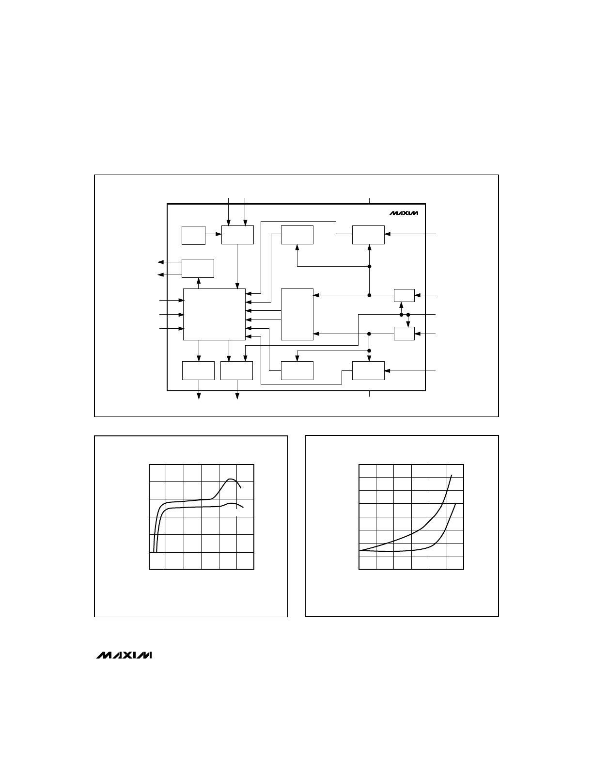
Figure 5 shows the various temperature cutoff points and
the typical voltages that the device will see at the TS pin.
V
LTF
(low-temperature fault voltage) refers to the volt-
age at TS when the battery temperature is too low, and
V
HTF
(high-temperature fault voltage) refers to the high-
temperature cutoff. If the voltage is outside these lim-
its, the MAX2003/MAX2003A will not enter fast-charge
mode. After fast-charge is initiated, the termination
point for high-temperature termination is V
TCO
(temper-
ature cutoff voltage), rather than V
HTF
. See Figure 5 for
TEMP LED status.
V
LTF
is set internally at 0.4V
CC
, so (with a 5V supply)
V
LTF
is 2V. V
TCO
is set up using external resistors to
determine the high-temperature cutoff after fast-charge
begins. V
HTF
is internally set to be (V
LTF
- V
TCO
) / 8
above V
TCO
.
Thermistors are inherently nonlinear with respect to
temperature. This nonlinearity is especially noticed
when
∆
T/
∆
t measurements are made to determine
charge termination. The simplest way around this is to
place a resistor-divider network in parallel with the ther-
mistor (Figure 6) to reduce the effects of nonlinearity.
The lowpass filter (R
T
, C
T
) placed on the TS pin attenu-
ates high-frequency noise on the signal seen by TS.
Charge Pending
Before fast-charge is initiated, the cell voltage and tem-
perature of the battery pack must be within the
assigned limits. If the voltage or temperature is outside
these limits, the device is said to be in a “charge-pend-
ing” state. During this mode, the CHG pin will cycle
low (LED on) for 0.125sec and high (LED off) for
1.375sec.
Fast-charge is normally initiated if the cell voltage is
greater than V
EDV
(end-of-discharge voltage). If the cell
voltage is too low (below V
EDV
), the device waits until
the trickle current brings the voltage up before fast-
charge is initiated. V
EDV
is set internally at 0.2V
CC
, so
(for a 5V supply) V
EDV
is 1V.
If the temperature of the cell is not between V
LTF
and
V
HTF
the device is also in a charge-pending state (see
Temperature Measurement section).
Initiate Fast-Charge
If the MAX2003/MAX2003A are out of the charge-pend-
ing state, fast-charge can be initiated upon one of the
following conditions:
•
Battery Replacement
•
Applying Power to the MAX2003/MAX2003A
(battery already present)
•
Digital Control Signal
During fast-charge, the CHG pin will be continuously
low (LED on). For the initial period of fast-charge (the
hold-off time), the voltage charge-termination methods
are disabled. The hold-off time is a function of the
charge rate selected by TM1 and TM2 (see Table 4).
NiCd/NiMH Battery Fast-Charge Controllers
8
_______________________________________________________________________________________
V
CC
= 5V
V
LTF
- V
TCO
V
LTF
= 0.4V
CC
1/8 (V
LTF
- V
TCO
)
7/8 (V
LTF
- V
TCO
)
V
HTF
V
TCO
V
SS
= 0V
OFF
ON
ON
TEMP LED
STATUS
Figure 5. Temperature Measurement Scale
RC FILTER
100k
R
T
V
CC
C
T
0.1
µ
F
NTC
TS
SNS
RT2
RT1
MAX2003
MAX2003A
Figure 6. Thermistor Configuration for Temperature Measurement
Battery Replacement
Before a battery is inserted, the BAT pin is pulled high-
er than the maximum cell voltage (MCV) by the resistor
(R
TR
) and the divider network (R
B1
/R
B2
) (Figure 1).
When the battery is inserted, the voltage per cell at BAT
falls from the default voltage to the battery voltage.
Fast-charge is initiated on a falling edge when the BAT
voltage crosses the voltage on MCV.
Applying Power to the MAX2003/MAX2003A
(battery already present)
There may be some cases where a battery is connect-
ed before power is applied to the MAX2003/
MAX2003A. When power is applied, the device goes
into reset mode for approximately 1.5sec and then
samples the CCMD and DCMD pins. Its charge status
is determined by the voltage at both the CCMD and
DCMD pins. Table 2 summarizes the various condi-
tions the MAX2003/MAX2003A might see on power-up.
Table 2 shows that the MAX2003/MAX2003A can be
set-up for fast-charge on power-up by making sure
CCMD and DCMD are at the same potential. If fast-
charge on power-up is not desired, make sure CCMD
and DCMD are at different logic levels during power-
up, and use a digital signal to control fast-charge (see
Digital Control section).
Digital Control
The CCMD pin can be used to initiate fast-charge. This
is useful when neither the power supply nor the battery
can be removed from the charger. The CCMD signal
needed to initiate fast-charge depends on the potential
at DCMD. If DCMD is low, a rising edge on CCMD initi-
ates fast-charge. If DCMD is high, a falling edge on
CCMD provides the fast-charge signal. Table 3 summa-
rizes the conditions used to start fast-charge.
Discharge-Before-Charge (optional)
The discharge-before-charge function is optional and
can be used to condition old batteries. It is especially
useful in NiCd batteries, since it alleviates the voltage
depression problems associated with partially dis-
charged NiCd cells. The discharge-before-charge
function is initiated by a rising edge into DCMD.
When the digital signal is applied, the DIS pin will be
pulled high, turning on the attached circuit and dis-
charging its battery. The discharge process continues
until the single cell voltage drops below 0.2V
CC
.
During the discharge phase, the CHG pin will be low
(LED on) for 1.375sec and high (LED off) for 0.125sec.
The MAX2003/MAX2003A does not control the current
during discharge-before-charge. If the discharge rate
is too great, the battery could overheat and be dam-
aged. The battery manufacturer will be able to specify
a safe discharge rate, but a rate of C or slower is typi-
cally acceptable. It is also important to choose compo-
nents (Q2, R
DIS
) that are rated for that particular
discharge rate. Since the gate-source drive for Q2 can
be as low as 4.5V, use a logic-level MOSFET.
Fast-Charge Current
The fast-charge current can be generated using two
categories of circuits:
•
Circuits with a sense resistor (R
SNS
)
•
Circuits without sense resistor (SNS tied to V
SS
)
Circuits with SNS Resistor
The standard application circuit of Figure 1 uses an
inductor and a switched mode of operation to supply
the current. The charge current is determined by the
sense resistor placed between the negative terminal of
the battery (SNS) and ground (V
SS
).
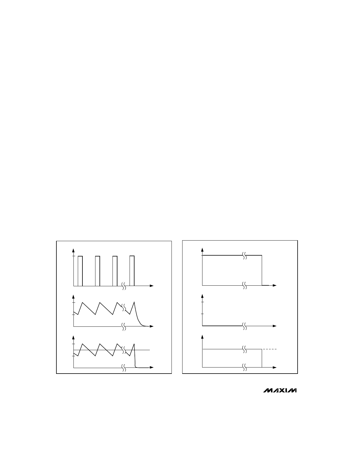
The SNS pin is the input to a comparator with hystere-
sis. If the voltage at SNS drops below 0.044V
CC
, the
MOD pin is turned on. If the SNS voltage is above
0.050V
CC
, MOD is turned off. In the switched mode of
operation, the SNS voltage ramps between 0.044V
CC
and 0.050V
CC
, which is 220mV and 250mV when V
CC
MAX2003/MAX2003A
NiCd/NiMH Battery Fast-Charge Controllers
_______________________________________________________________________________________
9
Table 2. Device Status on Power-Up if
Battery is Already Present
Table 3. Digital Control of Fast-Charge
(V
CC
and battery present)
•
The device does not enter fast-charge
immediately.
•
Fast-charge is initiated by the rising
edge of a pulse on CCMD.
Low
High
•
Fast-charge is initiated on power-up.
High
High
•
The device does not enter fast-charge
immediately.
•
Fast-charge is initiated by the falling
edge of a pulse on CCMD.
High
Low
CCMD
•
Fast-charge is initiated on power-up.
Low
Low
MAX2003/MAX2003A Status when
Power is Applied
DCMD
•
Fast-charge is initiated by a falling
edge on CCMD.
High
CCMD
•
Fast-charge is initiated by a rising
edge on CCMD.
Low
CCMD Status to Initiate Fast-Charge
DCMD
MAX2003/MAX2003A
is 5V (Figure 7). The average voltage at SNS, therefore,
is 235mV, and can be used to calculate the charge cur-
rent as follows:
I
CHARGE
= 0.235V / R
SNS
where R
SNS
is the sense resistor and I
CHARGE
is the
charge current required.
Circuits without SNS Resistor
In some applications (shown later), SNS is tied directly
to ground. In these cases, the MOD pin remains on
until any one charge-termination condition is exceeded
(Figure 8). A reasonable external current limit (such as
a current-limited DC source) must be provided for
these applications, to prevent battery damage due to
excessive charge currents.
Charge Termination
The MAX2003 has several charge-termination methods.
The termination method selected depends on the type
of battery and charge rate used. Table 1 summarizes
the conditions used to terminate fast-charge with differ-
ent battery types and charge rates.
Temperature Rate Termination
The Temperature Rate Termination (
∆
T/
∆
t) method ter-
minates fast-charge when a particular rate-of-change in
temperature is exceeded. As the battery begins fast-
charge, its temperature increases at a slow rate. When
the battery nears full capacity, this rate of temperature
change increases. When the rate of temperature
change exceeds a preset number, fast-charge is termi-
nated. This method of fast-charge termination can be
used for both NiCd and NiMH batteries.
The MAX2003 samples the voltage at the TS pin every 34
seconds and compares it with a value taken 68 seconds
earlier. Since an NTC thermistor is used for temperature
measurements, a gradual rise in temperature will result in
successively lower voltage readings. If the new reading is
more than 0.0032V
CC
(16mV for V
CC
= 5V) below the old
reading, fast-charge is terminated.
The MAX2003A varies the sampling interval as a function
of charge rate (Table 4). As the charge rate increases,
the sampling interval decreases, thereby allowing more
accurate termination of fast charge.
Note: This method of charge termination is valid only
when the battery’s temperature is between V
LTF
and
V
TCO
(Figure 5).
NiCd/NiMH Battery Fast-Charge Controllers
10
______________________________________________________________________________________
TIME
TIME
TIME
0
0
0
MOD
SNS
I
LOAD
0.044
V
CC
0.050
V
CC
V
CC
I
BAT
FAST CHARGE
FAST-CHARGE
TERMINATE
Figure 7. Current Regulation with an SNS Resistor
TIME
TIME
SNS = 0V
TIME
0
0
MOD
SNS
I
LOAD
0.044
V
CC
0.050
V
CC
V
CC
I
BAT
FAST CHARGE
FAST-CHARGE
TERMINATE
Figure 8. Current Regulation without an SNS Resistor
Negative Delta Voltage Termination
The Negative Delta Voltage Termination (-
∆
V) method
measures a negative delta voltage to determine termi-
nation of fast-charge. After maximum charge is
reached, the terminal voltage of NiCd batteries
declines significantly, whereas the terminal voltage of
NiMH batteries does not. Hence, the -
∆
V method of
fast-charge termination is suitable for NiCd batteries,
but not for NiMH batteries.
The MAX2003/MAX2003A sample the BAT pin every 34
seconds and compare it with all previous values. If the
new value is less than any of the previous values by
more than 12mV, a negative delta voltage has been
detected and fast-charge is terminated.
Note: This method of charge termination is valid only
when the voltage at BAT is between V
MCV
and V
MCV
-
0.2V
CC
.
The -
∆
V method is inhibited during the hold-off time to
prevent false termination of fast-charge. The hold-off
time depends on the charge rate used, and is selected
by the inputs TM1 and TM2 (as shown in Table 4).
After the hold-off time has expired, the device begins to
monitor BAT for a voltage drop.
Maximum Temperature Termination
The Maximum Temperature Termination method is used
as a safety net to prevent problems, and should never
be needed under normal operation of the charger. The
maximum temperature that the battery can reach during
fast-charge has a corresponding voltage—the tempera-
ture cutoff voltage (V
TCO
), as seen in Figure 5. This
voltage is set externally at the TCO pin using a resistor
divider from V
CC
. Although rarely experienced, an
excessively low temperature will also terminate fast-
charge. The minimum temperature is the low tempera-
ture fault (V
LTF
). This value is internally set at 0.4V
CC
.
When the thermistor exceeds these temperature limits,
fast-charge is terminated. The thermistor configuration
shown in Figure 5 is used to measure the battery’s tem-
perature and scale it to operate from V
LTF
to V
TCO
.
Resistors R
T1
and R
T2
are calculated to provide the
required cutoff at V
TCO
. See the
Design Guide section
for a detailed design example.
Maximum Voltage Termination
The Maximum Voltage Termination method is another
safety feature designed to work if something is drastically
wrong. Under normal operation of the charger, this condi-
tion should only be reached when the battery is removed.
The maximum cell voltage expected is applied at the
MCV pin using a resistor-divider network. If the cell volt-
age measured at BAT exceeds that at MCV, fast-
charge is terminated. For most applications using both
NiCd and NiMH batteries, this voltage (V
MCV
) can be
set to 1.9V.
The MAX2003/MAX2003A do not terminate fast-charge
if the maximum voltage is reached before the hold-off
time has expired. If the cell voltage is greater than the
MCV during the hold-off time, the device will continue
fast-charge until the hold-off time has expired, and then
it will terminate fast-charge. The hold-off time is deter-
mined by the inputs TM1 and TM2, as shown in Table 4.
Maximum Timeout Termination
The final method is Maximum Timeout Termination,
which (like the maximum voltage and maximum tem-
perature methods) is another backup safety feature.
The timeout time depends on the charge rate selected
and is set by the control signals TM1 and TM2. Table 4
shows a list of different timeout periods available for dif-
ferent control-signal inputs. If the timeout is reached
before any other termination method is seen, fast-
charge is terminated to protect the charger and battery.
Top-Off Charge
Top-off charge is used to provide the last bit of charge
needed to reach full capacity after fast-charge is termi-
nated. Top-off charging puts slightly more energy into
the battery than simple trickle charging, and can be
used for both NiCd and NiMH batteries. Select it by
choosing the appropriate control signals on TM1 and
TM2 (Table 4).
MAX2003/MAX2003A
NiCd/NiMH Battery Fast-Charge Controllers
______________________________________________________________________________________
11
*Enable
100
23
4C
V
CC
V
CC
Disable
100
23
*Enable
410
90
*Enable
200
45
2C
V
CC
Open
C
V
CC
GND
*Enable
820
180
C/2
Open
V
CC
4C
Open
Open
Disable
410
90
Disable
200
45
2C
Open
GND
C
GND
V
CC
Disable
820
180
C/2
GND
Open
Disable
Top-Off
Charge
140
Hold-Off
Time
∆
V/MCV
(sec)
360
Fast-
Charge
Timeout
(min)
TM1
C/4
GND
GND
Fast-
Charge
Rate
TM2
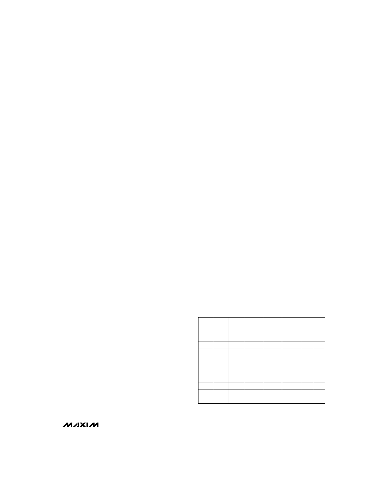
Table 4. Programmable Inputs for
Timeout/Hold-Off/Fast-Charge/Top-Off/
Pulse Trickle (V
CC
= 5V)
0.5
1
0.5
0.5
0.5
1
1
1
Disable
MAX2003A
Trickle
Charge (s)
On/Off
* MAX2003 is on for 4sec and off for 30sec.
MAX2003A is on for 0.5sec and off for 3.5sec.
16
32
64
128
16
32
64
128
MAX2003/MAX2003A
The top-off charge is done at 1/8 the fast-charge rate.
For the MAX2003, the MOD pin is activated in every 34
second period to supply current to the battery for 4
seconds (MOD oscillates for 4 seconds and stays low
for 30 seconds) (Figure 7). If external regulation is
used (SNS tied to ground), MOD stays high for 4 sec-
onds and low for 30 seconds (Figure 8). This top-off
process continues until the fast-charge timeout (Table
4) is exceeded, or if a maximum temperature or maxi-
mum voltage condition is detected. The MAX2003A is
slightly modified to turn the MOD pin on for 0.5sec in
every 4 second period. This shorter on-time reduces
battery heat and increases charge acceptance. During
the top-off charge, the CHG pin will cycle low (LED on)
for 0.125sec and high (LED off) for 0.125sec.
Trickle-Charge
A trickle-charge is applied to the battery after fast-
charge and top-off charge have terminated to compen-
sate for self discharge. There are two methods of
trickle charge: constant and pulsed.
Pulsed Trickle-Charge (MAX2003A)
The MAX2003A provides a pulsed trickle-charge to the
battery by turning on the MOD pin briefly during a fixed
period of time. The duty cycle of the pulse is a function of
the programmable inputs TM1 and TM2 (Table 4 ). The
MAX2003A does not use the trickle resistor to provide the
trickle charge. However, the trickle resistor cannot be
entirely omitted because it is also used for the battery-
detect circuitry.
Constant Trickle-Charge (MAX2003)
The MAX2003 provides a steady trickle-charge to the
battery by connecting a resistor from the DC supply to
the positive battery terminal. This resistor has a dual
purpose, in that it provides a trickle-charge and pulls
the BAT pin above the MCV when the battery is absent.
The trickle-charge rate depends on the type of battery
used. For NiCd batteries, a nominal trickle-charge rate
would be C/16, and NiMH batteries could use a rate of
C/40. The resistor value used depends on the maxi-
mum DC voltage and the typical battery voltage. For
example, a six-cell 800mAh NiCd pack with a nominal
voltage of 1.2V per cell would have a total voltage of
1.2V x 6V = 7.2V. If the DC supply voltage used is 14V,
the voltage across the trickle resistor would be 14.0V -
7.2V = 6.8V. The trickle current needed would be C/16
= 800 / 16 = 50mA. The trickle resistor would therefore
be R
TR
= 6.8V / 50mA
≈
150
Ω
. Similar calculations
should be made for NiMH batteries using C/40 as the
trickle-charge rate.
If a trickle-charge is not needed, a higher value of trick-
le resistor (like 100k
Ω
) can be selected to sense the
battery insertion.
Charge Status
The CHG pin is connected to a LED that indicates the
operating mode. Table 5 summarizes the different
charge conditions.
_______________________Design Guide
Using the circuit of Figure 1 as an example, the follow-
ing nine steps show how to design a 1.7A switch-mode
fast-charger that can charge a Duracell DR17 (NiMH
six-cell battery pack with a 1700mAh capacity).
1) Select DC Power Supply
. The first step is to select
the DC power supply (such as a wall cube). The mini-
mum supply voltage should have a supply equal to
about 2V per cell, plus 1V headroom for external cir-
cuitry ((2V/cell) + 1V). The minimum supply voltage
must be greater than 6V. If, as in our example, there
are six cells, a minimum supply of about 13V is needed
((6 cells x 2V) + 1V).
2) Determine Charge Rate
. The charge rate, or fast-
charge current (I
FAST
), is determined by two factors:
the capacity of the battery, and the time in which the
user wants the battery to be charged. The battery
manufacturer recommends a maximum fast-charge
rate, which must not be exceeded.
Capacity of Battery (mAh)
I
FAST
(mA) = ————————————
Charge Time (h)
For example, if a 1700mAh battery needs to be charged in
two hours (C/2), a fast-charge current of at least 850mA is
needed. A charge rate of C/2 will ideally charge a battery
in two hours but, because of inefficiencies in a battery’s
chemical processes, the time could be 30% to 40% more.
Our example circuit (Figure 1) charges the Duracell bat-
tery pack at a C rate of 1.7A, which should fully charge a
discharged battery in approximately 80 minutes.
NiCd/NiMH Battery Fast-Charge Controllers
12
______________________________________________________________________________________
Table 5. Charge Status
LED on for 0.125sec, off for
0.125sec
Charge Complete and Top-
Off
LED on
Fast-Charge
LED on for 1.375sec, off for
0.125sec
Discharge-Before-Charge
LED on for 0.125sec, off for
1.375sec
Charge Pending
Charge State
LED off
Battery Absent
CHG LED Status
3) Select Sense Resistor
. The sense resistor deter-
mines the rate at which the battery is fast-charged. The
sense pin, SNS, has an average voltage of 235mV (see
Detailed Description) and, since the charge current
(I
FAST
) is known from above, the resistor can be calcu-
lated by:
R
SNS
= V
SNS
/ I
FAST
= 0.235 / I
FAST
In this example, a fast-charge current of 1.7A requires
a sense resistor of about 0.14
Ω
(1 watt).
4) Select TM1 and TM2
. Once the charge rate is
determined, Table 4 can be used to select the TM1 and
TM2 inputs. TM1 and TM2 set the safety timeout, hold-
off time, and top-off enable (see
Fast-Charge
Termination section in the Detailed Description).
In Figure 1, a fast-charge rate of C with top-off would
require TM1 to be GND and TM2 to be V
CC
.
5) Select R
B1
and R
B2
. The MAX2003A requires the
user to select R
B1
and R
B2
to indicate the number of
cells in the battery. The total resistance value (R
B1
+
R
B2
) should be between 100k
Ω
and 500k
Ω
to prevent
any problems with noise. In Figure 1 (with six cells) R
B1
is selected to be 100k
Ω
and, from the following equation:
R
B2
= R
B1
/ (Number of Cells - 1) = 100k
Ω
/ (6 - 1)
R
B2
can be calculated to be 20k
Ω
.
6) Select Temperature-Control Components
. Most
sealed rechargeable battery packs have a built-in ther-
mistor to prevent air currents from corrupting the accurate
temperature measurements. The thermistor size and tem-
perature characteristics can be obtained from the bat-
tery-pack manufacturer, to help in designing the rest of
the circuit. Three-terminal battery packs that incorporate
a thermistor generally share a common connection for the
thermistor and the battery negative terminal. Large charg-
ing currents may produce voltage drops across the com-
mon negative connector, causing errors in thermistor
readings. Using separate contacts for the thermistor
ground sense and the battery ground sense at the nega-
tive battery terminal will reduce these errors. If an external
thermistor is to be used, take care to ensure that it is
placed in direct contact with the battery, and that the bat-
tery/thermistor set-up is placed in a sealed container.
Neither NiCd nor NiMH batteries should be fast-
charged outside the maximum and minimum tempera-
ture limits. However, some applications also require
termination using the
∆
T/
∆
t criterion. The resistors R
T1
and R
T2
(Figure 1) will determine the temperature cutoff
(V
TCO
) and the rate-of-change of temperature (
∆
T/
∆
t).
Though NiCd batteries do not always require termina-
tion using the
∆
T/
∆
t feature, it is not possible to isolate
and disable this mode. It is therefore recommended
that NiCd and NiMH batteries use the same
∆
T/
∆
t termi-
nation parameters.
The Duracell DR17 battery pack used in our example
circuit recommended a low fault temperature (V
LTF
) of
+10°C and a maximum temperature cutoff (V
TCO
) of
+50°C. These maximum temperature values will never
be reached in most cases, but are used as a safety net
to prevent battery damage. According to Duracell, the
10k
Ω
thermistor inside the pack varies from 17.96k
Ω
at
+10°C to 4.16k
Ω
at +50°C.
The circuit in Figure 1 will be designed so that a battery
temperature change of 1°C/min will result in fast-charge
termination. At 1°C/min, the battery will take 40 minutes
to change 40°C (10°C to 50°C). Since a charge rate of
C is used for this example, Table 4 shows that the
MAX2003A samples the TS pin every 68 seconds and
compares it with a value taken 136 seconds earlier.
The device will terminate fast-charge if the voltage at
TS changes by more than 0.0032V
CC
(16mV for V
CC
=
5V). At a charge rate of 16mV every 136 seconds, the
TS pin will charge 280mV in 40 minutes (40min x
60sec/min x 16mV/136sec).
The low fault temperature (V
LTF
) is set internally at
0.4V
CC
, which is 2.0V for a supply of 5V. The tempera-
ture cutoff voltage (V
TCO
) will be 280mV below V
LTF
, or:
V
TCO
= (2.00V - 0.28V) = 1.72V
Figure 5 shows that, at any given temperature:
V
TS
= V
CC
(R
T2
|| R
NTC
) / [(R
T2
|| R
NTC
) + R
T1
]
When the battery temperature is +10°C, the voltage is:
V
TS10
= V
CC
(R
T2
|| R
NTC10
) / [(R
T2
|| R
NTC10
) + R
T1
]
And at +50°C:
V
TS50
= V
CC
(R
T2
|| R
NTC50
) / [(R
T2
|| R
NTC50
) + R
T1
]
MAX2003/MAX2003A
NiCd/NiMH Battery Fast-Charge Controllers
______________________________________________________________________________________
13
V
CC
R2
R3
R1
MCV
TCO
Figure 9. Resistor Configuration for MCV and TCO
MAX2003/MAX2003A
From solving these simultaneous equations:
R
T2
= [(X) (R
NTC10
) - (R
NTC50
)] / (1 - X)
R
T1
= [(R
T2
) (R
NTC10
) (V
CC
- V
TS10
)] / [V
TS10
(R
T2
+
R
NTC10
)].
[(R
NTC50
)(V
TS10
)(V
CC
- V
TS50
)]
where X = _____________________________
[(R
NTC10
) (V
TS50
) (V
CC
- V
TS10
)]
Using R
NTC50
= 4.16k
Ω
, R
NTC10
= 17.96k
Ω
, V
TS50
=
1.72V, and V
TS10
= 2.00V, it can be calculated that R
T1
= 1.599k
Ω
and R
T2
= 2.303k
Ω
.
Select preferred resistor values for R
T1
(2.21k
Ω
) and
R
T2
(1.62k
Ω
). The actual voltages on MCV and TCO
can be verified as follows:
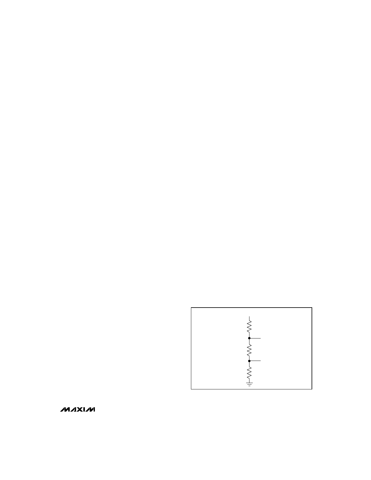
7) Select Maximum Cell Voltage (MCV) and
Temperature Cutoff (TCO)
. The MCV and TCO can
be selected with a resistor-divider combination (Figure
9). In our example, TCO has been set to +10°C, which
corresponds to a voltage of 1.72V at the TS pin. The
MCV for most fast-charge batteries can be set to about
1.9V. To minimize the current load on V
CC
, choose R1
in the range of 20k
Ω
to 200k
Ω
. In this example, choose
R1 = 60.4k
Ω
, then calculate R3 and R2 as follows:
R3 = (V
TCO
x R1) / (V
CC
- V
MCV
) = 33.5k
Ω
(1%)
and
R2 = (V
MCV
x R1) / (V
CC
- V
MCV
) - R3 = 3.51k
Ω
(1%)
Select preferred resistor values for R2 (3.48k
Ω
) and R3
(33.2k
Ω
). The actual voltages on MCV and TCO can
be verified as follows :
V
TCO
= V
CC
(R3) / (R1 + R2 + R3) = 1.71V
and
V
MCV
= V
CC
(R2 + R3) / (R1 + R2 + R3) = 1.89V.
8) Select Trickle Resistor (MAX2003 only).
The trick-
le resistor (R
TR
) is selected to allow a trickle-charge
rate of C/16 to C/40. The resistor value is given by:
R
TR
= (V
DC
- V
BAT
) / I
TR
where I
TR
is the required trickle current, V
DC
is the DC
supply voltage, and V
BAT
is the number of cells times
the cell voltage after fast-charge.
In our example, the 1700mAh NiMH battery needs a
trickle current of C/40; i.e., 42mA (1700mAh/40h).
Therefore, the minimum voltage (from the formula
above) is as follows:
R
TR
= [13.0V - (6 x 1.2V)] / 42mA
≈
150
Ω
The maximum power dissipated in the resistor can be
calculated by:
Power = (V
DC
- V
BAT(MIN)
)
2
/ R
TR
where V
BAT(MIN)
is the minimum cell voltage, V
DC
is the
DC supply voltage, and R
TR
is the trickle resistor value.
Since a shorted battery could have 0V, this must be the
minimum cell voltage possible. Therefore the power
dissipated in the trickle resistor would be:
Power = (13 - 0)
2
/ 150 = 1.2W
A 2W, 150
Ω
resistor should be sufficient for the trickle-
charge resistor. For the MAX2003A, refer to
Trickle-
Charge section.
9) Select Inductor
. The inductor value can be calcu-
lated using the formula:
V
L
= L
δ
i /
δ
t
where V
L
is the maximum voltage across the inductor, L
is the minimum inductor value,
δ
i is the change in induc-
tor current, and t is the minimum on-time of the switch.
V
V
R
II R
R
II R
R
5 1.62k II 17.96k
1.62k II 17.96k
2.21k
2.01V
V
V
R
II R
R
II R
R
5 1.62k II 4.16k
1.62k II 4.16k
2.21k
1.72V.
TS10
CC
T2
NTC10
T2
NTC10
T1
TS50
CC
T2
NTC50
T2
NTC50
T1
=
(
)
(
)
+
[
]
=
Ω
Ω
(
)
Ω
Ω
(
)
+
Ω
[
]
=
=
(
)
(
)
+
[
]
=
Ω
Ω
(
)
Ω
Ω
(
)
+
Ω
[
]
=
NiCd/NiMH Battery Fast-Charge Controllers
14
______________________________________________________________________________________
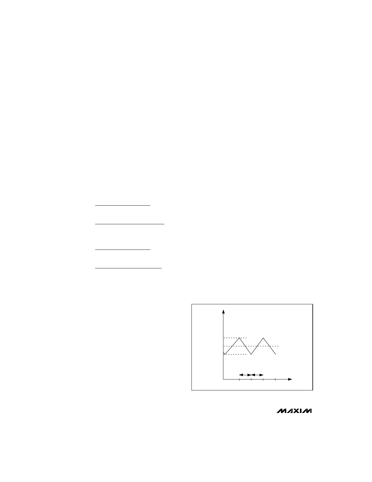
I
LOAD
I
MAX
= 1.9A
INDUCTOR
CURRENT
I
MIN
= 1.5A
TIME
δ
i = I
MAX
- I
MIN
T
OFF
T
ON
Figure 10. Inductor-Current Waveform in Continuous-
Conduction Mode

In order to provide high currents with minimum ripple,
the device must function in the continuous-conduction
mode. Figure 10 shows a current waveform of an
inductor in the continuous-conduction mode (where the
coil current never falls to zero).
The average load current (I
LOAD
) through the inductor
must be 1.7A, so a peak current (I
MAX
) of 1.9A should
give a fairly low ripple while keeping the inductor size
minimal. This means that the total current change (Figure
10) across the inductor is
δ
i = 2 (1.9 - 1.7) = 0.4A.
The maximum voltage across the inductor is present
when the battery voltage is at its minimum. The mini-
mum cell voltage at the start of fast-charge will be 1V
per cell, giving a battery voltage of 6V for 6 cells. The
maximum voltage (V
L
) across the inductor is therefore:
V
L
= (input voltage - minimum battery voltage)
The input voltage for this application is 13V, so the
maximum voltage is:
V
L
= (13V - 6V) = 7V
The minimum on-time
δ
t of the switch is given by:
δ
t = (V
OUT
/ V
IN
) x PERIOD
where V
OUT
is the minimum battery voltage, V
IN
is the
maximum input voltage, and PERIOD is the period of
the switching signal.
The maximum input voltage for this application will be
14V, and the maximum allowed switching frequency of
100kHz gives a period of 10µs. The minimum on-time
will therefore be:
δ
t = (V
OUT
/ V
IN
) x PERIOD = (6V / 13V) x 10µs = 4.62µs
The inductor value can be calculated from:
L = V
δ
t /
δ
i = (7V x 4.62µs) / 0.4A = 81µH.
If this inductor value is used, the actual switching fre-
quency will be lower than the 100kHz expected, due to
comparator delays and variations in the duty cycle.
The inductor value selected for our application will be
100µH—a preferred value just above the calculated
value. It is important to choose the saturation current
rating of the inductor to be a little higher than the peak
currents, to prevent the inductor from saturating during
operation. The inductor must be selected to ensure
that the switching frequency of the MOD pin will not
exceed the 100kHz maximum.
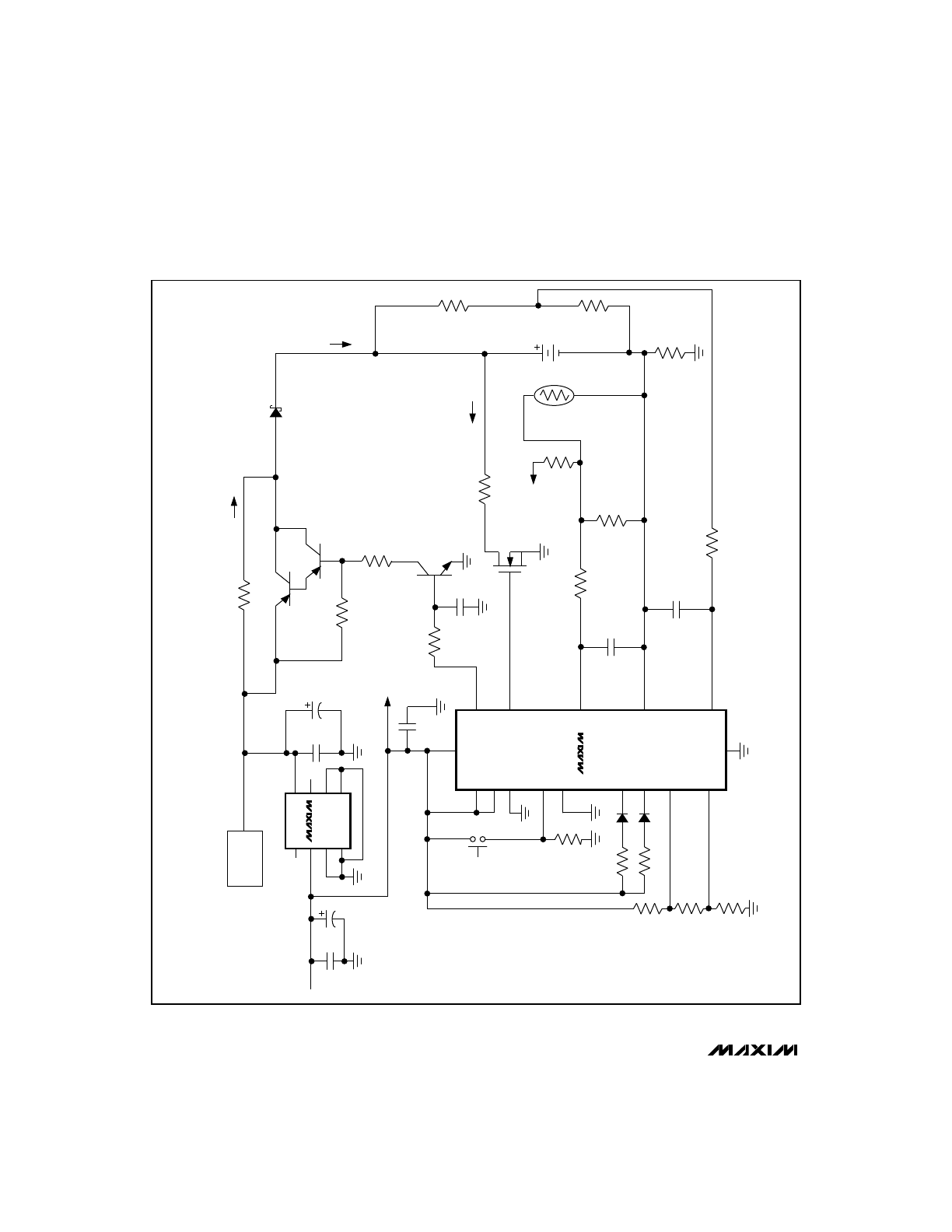
Additional Applications
_________________________Information
The MAX2003/MAX2003A can use several other cir-
cuits to charge batteries. Figure 9 shows a circuit that
uses a Darlington transistor to regulate the current a
six-cell NiCd battery pack receives. Figure 10 shows a
gated current-limited supply being used to charge a
Duracell NiMH battery pack. Table 6 lists the external
components used in these two application configura-
tions.
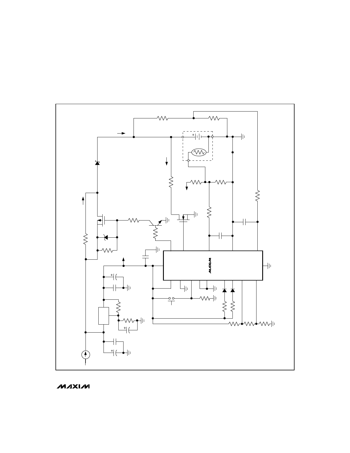
Linear Regulation of Charge Current
The circuit in Figure 11 uses an inexpensive transistor
to provide the charge current. Since the input for the
MAX667 can tolerate up to 16V, this circuit can charge
up to 7 cells. The MAX667 can be replaced with a dif-
ferent regulator if more cells need to be charged. The
DC source must supply a voltage equal to 2x the num-
ber of cells, plus 2V overhead to accommodate the
drop across external components.
When fast-charge is initiated, the voltage at the SNS pin
is sampled and compared to the trip levels (220mV low
and 250mV high). If the voltage at SNS is below
220mV, the MOD pin will switch high, and the 10k/1µF
RC lowpass filter will pull high, turning on the NPN tran-
sistor. This will pull the base of the Darlington TIP115
low, turning it on and allowing current to flow into the
battery. When the current through the battery and SNS
resistor are high enough, the voltage at SNS will
exceed 250mV and the MOD pin will turn off.
The amount of current the battery receives depends on
the resistor between SNS and V
SS
. In our example cir-
cuit, the average current through the SNS resistor will
be:
I
SNS(AVG)
= V
SNS(AVG)
/ R
SNS
= 0.235 / 0.28 = 0.84A
The maximum current the resistor will receive is:
I
SNS(MAX)
= V
SNS(MAX)
/ R
SNS
= 0.25 / 0.28 = 0.90A
The Darlington transistor must be biased to ensure that
a minimum of 0.90A will be supplied. This minimum
MAX2003/MAX2003A
NiCd/NiMH Battery Fast-Charge Controllers
______________________________________________________________________________________
15
Table 6. External Component Sources
(602) 244-4015
(602) 244-3742
Motorola
Power
MOSFET &
Darlington
Transistor
(904) 462-4726
(203) 791-3273
(904) 462-3911
Energizer
Power
Systems
(800) 431-2658
Duracell
Battery
(619) 549-4791
(510) 460-5498
Fax Number
(800) 235-5445
Alpha
Thermistor
Thermistor
Device
(510) 734-3060
Advanced
Power
Solutions
Power
Supply
Phone
Number
Manufacturer
MAX2003/MAX2003A
NiCd/NiMH Battery Fast-Charge Controllers
16
______________________________________________________________________________________
MAX2003
MAX2003A
MAX667
MOD
3
R1
60.4k
1k
100k
1k
R2
3.48k
R3
33.2k
14
16
7
6
5
8
1
14V/2A
DC SOURCE
R
TR
100k
(*150
Ω
(2W))
2
5V OUT
IN
3
0.1
µ
F
47
µ
F
0.1
µ
F
47
µ
F
*TRICKLE-CHARGE
RATE
C/16
1N5822
0.1
µ
F
4
15
6
9
7
R
B1
100k
R
B2
20k
R
SNS
0.294
Ω
1%
(1W)
800mAh
6 NiCd
ALPHA
CURVE A
THERMISTOR
R
DIS
9
Ω
(10W)
NTC
R
T
100k
R
B
100k
DISCHARGE
RATE
1C
CHARGE
RATE
1C
C
T
0.1
µ
F
1
µ
F
C
B
0.1
µ
F
D
G
S
TO V
CC
R
T1
2.21k
10k
10k
TIP115
HEATSINK
6.8k
R
T2
1.62k
Q2
N
MMSF5NO3HD
Q3
2N2222
5
4
2
1
12
13
11
10
DIS
TS
SNS
BAT
V
SS
V
CC
V
CC
DVEN
PUSH TO
DISCHARGE
TM2
TM1
DCMD
TEMP
CHG
MCV
TC0
LED
LED
CCMD
8
Q1
*COMPONENT USED FOR MAX2003.
Figure 11. Linear Mode to Charge NiCD Batteries with -
∆
V Termination
MAX2003/MAX2003A
NiCd/NiMH Battery Fast-Charge Controllers
______________________________________________________________________________________
17
MAX2003
MAX2003A
MOD
5
R1
60.4k
1k
100k
1k
R2
3.48k
R3
33.2k
14
16
LM317
243
Ω
R
TR
100k
*180
Ω
(2W)
Q1
P
MMDF3P03HD
22
µ
F
22
µ
F
22
µ
F
732
Ω
ADJ
5V OUT
IN
OUT
19V
I
LIMITED
V
SOURCE
2.6A
0.1
µ
F
0.1
µ
F
*TRICKLE-CHARGE
RATE
C/40
1N5822
0.1
µ
F
15
6
9
7
R
B1
80.6k
R
B2
10k
2600mAh
9 NiMH
R
DIS
4
Ω
(20W)
NTC
R
T
100k
R
B
100k
DISCHARGE
RATE
1C
C
T
0.1
µ
F
C
B
0.1
µ
F
D
G
DURACELL DR35
S
TO V
CC
R
T1
2.21k
12V ZENER
1k
D
S
G
10k
R
T2
1.62k
Q2
N
MMSF3N03HD
Q3
2N2222
2
4
1
3
12
13
11
10
DIS
TS
SNS
BAT
V
SS
V
CC
V
CC
TM2
PUSH TO
DISCHARGE
TM1
DCMD
TEMP
CHG
MCV
TC0
LED
LED
DVEN
CCMD
1k
CHARGE
RATE
1C
*COMPONENT USED FOR MAX2003.
Figure 12. Current-Limited Mode for NiMH Batteries with
∆
T/
∆
t Termination
MAX2003/MAX2003A
current value must be sufficiently guardbanded to
ensure the limiting factor is the SNS resistor, and not
the transistor. In our example, the maximum current
supplied by the Darlington will be guardbanded to
1.8A. Since the beta of the Darlington is typically 1000,
the base current needed will be:
I
B
= I
C
/ BETA = 1.8A / 1000 = 1.8mA
The emitter of the TIP115 will see 14V, so the base will
see about 12.6V. When the MOD pin is high, the
2N2222 transistor is on and the base resistor will be:
R
B
= V
B
/ I
B
= 12.6V / 1.8mA
≈
6.8k
Ω
This 1.8A current will never be reached because MOD
will be off when the SNS voltage reaches 0.25V (0.9A).
Current-Limited Supply
The circuit in Figure 12 is set up to charge a Duracell
DR35 battery pack (nine cells, 2.6Ah) using a 19V, 2.6A
current-limited power supply provided by Advanced
Power Solutions. Since many power supplies have
built-in current limiting, very few external components
are required for this charging method.
The SNS pin in this circuit is tied directly to V
SS
. This
signals the MOD pin to stay high until a termination
condition is met. When MOD is high, the NPN transis-
tor is turned on, hence pulling the gate of the MOSFET
low. This turns the MOSFET on and supplies current to
the battery at the current limit of the source (2.6A). The
12V zener diode is placed between the source and
gate of the FET to ensure the FET’s maximum source-
drain voltage is not exceeded.
When a termination condition is reached, the MOD pin
goes low to turn off the FET and terminate the fast-
charge current.
NiCd/NiMH Battery Fast-Charge Controllers
18
______________________________________________________________________________________
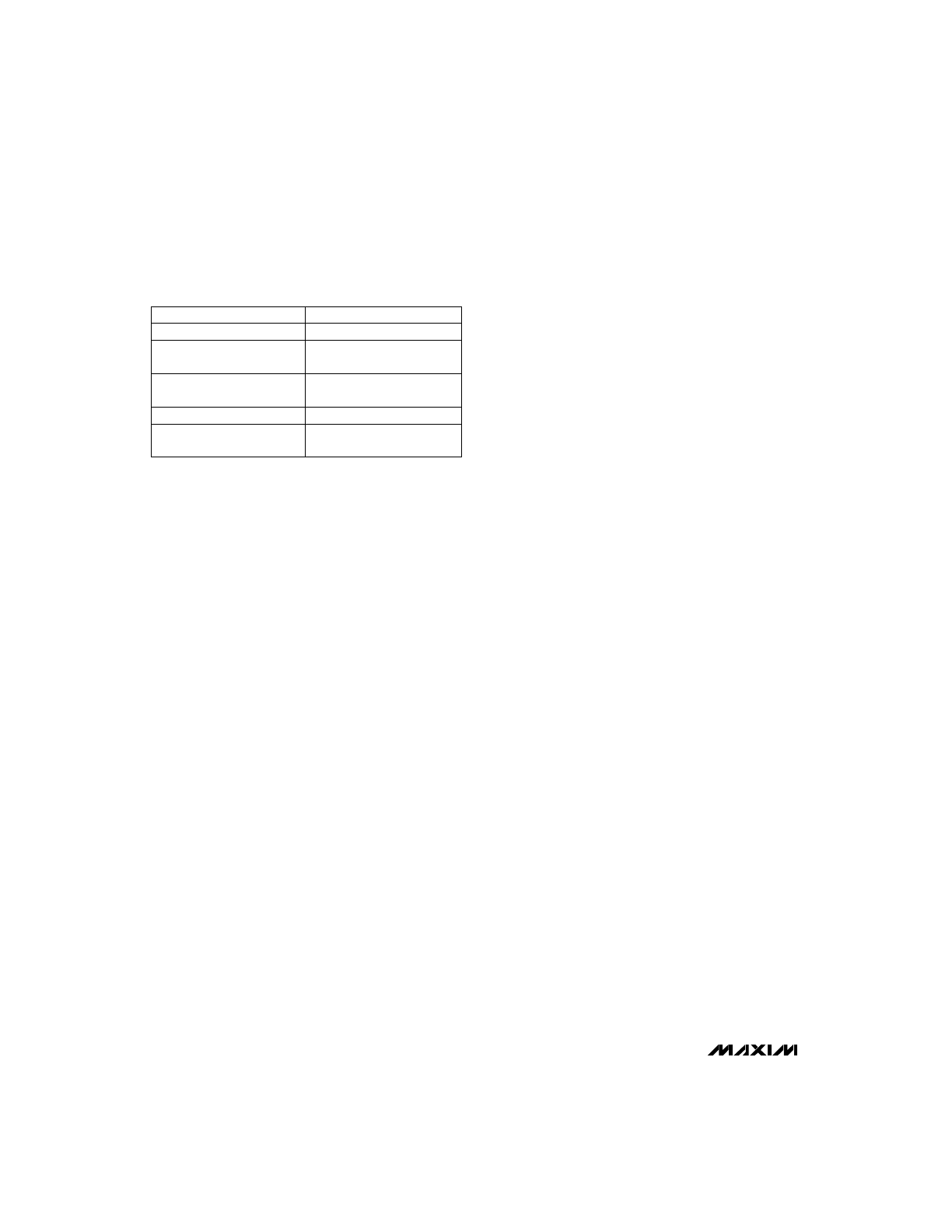
Table 7. Operation Summary
Discharge initiated with temperature
and voltage within set limits.
Discharge
Fast-charge initiated and tempera-
ture or voltage outside the set limits.
Charge Pending
a) Power applied and voltage at
CCMD = DCMD
b ) DCMD = Low, CCMD = Rising
Edge (power already present)
c ) DCMD = High, CCMD = Falling
Edge (power already present)
Initiate Fast-Charge
Rising edge on DCMD
Initiate Discharge
Charge Status
(V
BAT
- V
SNS
)
≥
V
MCV
Battery Absent
Conditions
Low
Low
Low
Low
Low
MOD Status
High
Low
Low
Low
Low
DIS
Status
1.375
0.125
—
—
—
CHG LED Status
0.125
1.375
Continuous
Continuous
Continuous
Pulse current provided by pulsing
MOD pin after fast-charge/top-off.
Pulsed Trickle-
Charge (MAX2003A)
Trickle current provided by external
resistor after fast-charge/top-off.
Constant Trickle-
Charge (MAX2003)
Charge complete and top-off
enabled without exceeding temper-
ature and voltage limits.
Top-Off Charge
Exceed one of the five termination
conditions.
Charge Complete
Fast-charge initiated with tempera-
ture and voltage within set limits.
Fast-Charge
Pulsed according to charge rate
(Table 4).
Low
MAX2003A: Activate for 0.5sec in
every 4sec period.
MAX2003: Active for 4sec in
every 34sec period.
Low
If V
SNS
> 0.050V
CC
, MOD = Low
If V
SNS
> 0.044V
CC
, MOD = High
Low
Low
Low
Low
Low
0.125
0.125
0.125
0.125
Continuous
0.125
0.125
0.125
0.125
—
LED On
(Low)
(sec)
LED Off
(High)
(sec)
MAX2003/MAX2003A
NiCd/NiMH Battery Fast-Charge Controllers
______________________________________________________________________________________
19
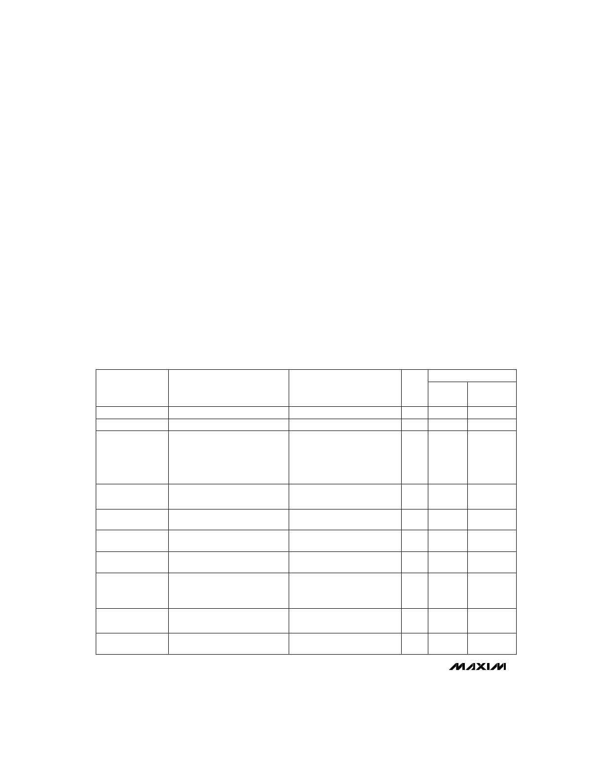
___________________Chip Topography
MOD
DCMD
CCMD
0.089"
(2.261mm)
0.086"
(2.184mm)
BAT
DVEN
DIS
V
CC
CHG
TEMP
MCV
TM1
TM2
TS
V
SS
SNS
TCO
TRANSISTOR COUNT: 5514
SUBSTRATE CONNECTED TO V
SS
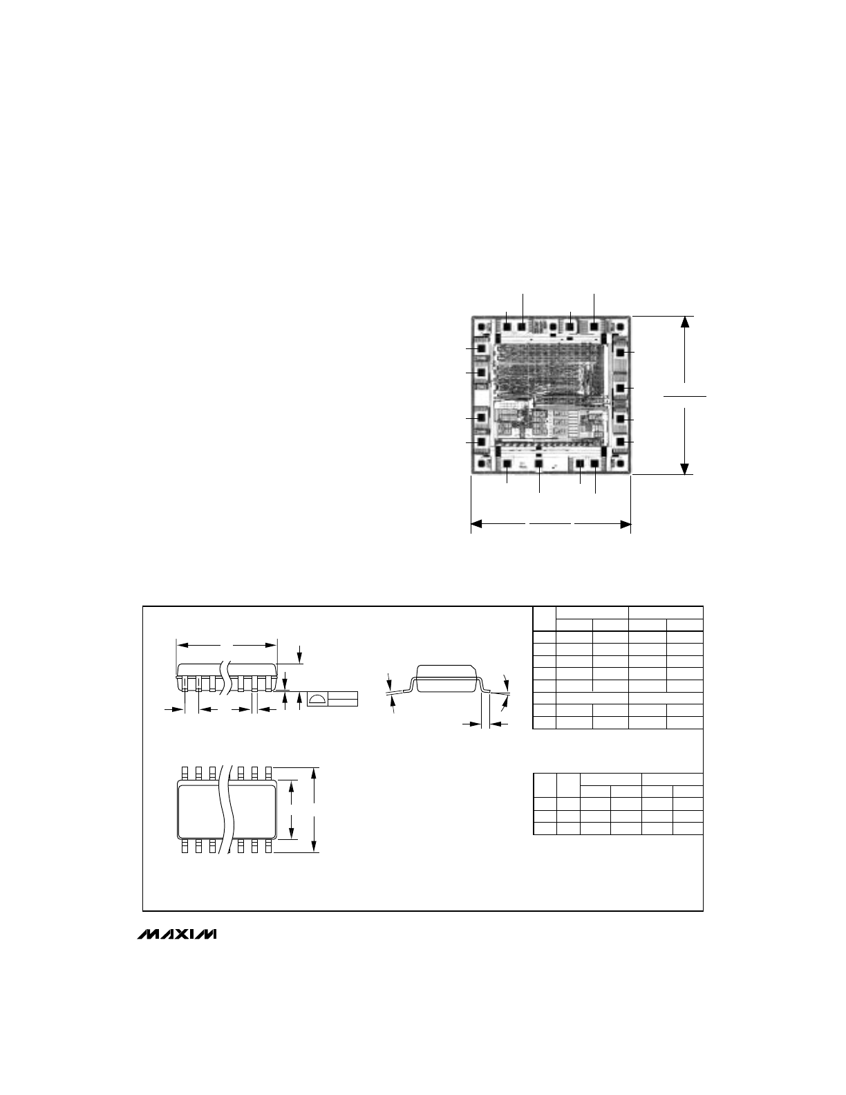
________________________________________________________Package Information
DIM
A
A1
B
C
E
e
H
L
MIN
0.053
0.004
0.014
0.007
0.150
0.228
0.016
MAX
0.069
0.010
0.019
0.010
0.157
0.244
0.050
MIN
1.35
0.10
0.35
0.19
3.80
5.80
0.40
MAX
1.75
0.25
0.49
0.25
4.00
6.20
1.27
INCHES
MILLIMETERS
21-0041A
Narrow SO
SMALL-OUTLINE
PACKAGE
(0.150 in.)
DIM
D
D
D
MIN
0.189
0.337
0.386
MAX
0.197
0.344
0.394
MIN
4.80
8.55
9.80
MAX
5.00
8.75
10.00
INCHES
MILLIMETERS
PINS
8
14
16
1.27
0.050
L
0°-8°
H
E
D
e
A
A1
C
0.101mm
0.004in.
B
MAX2003/MAX2003A
NiCd/NiMH Battery Fast-Charge Controllers
20
______________________________________________________________________________________
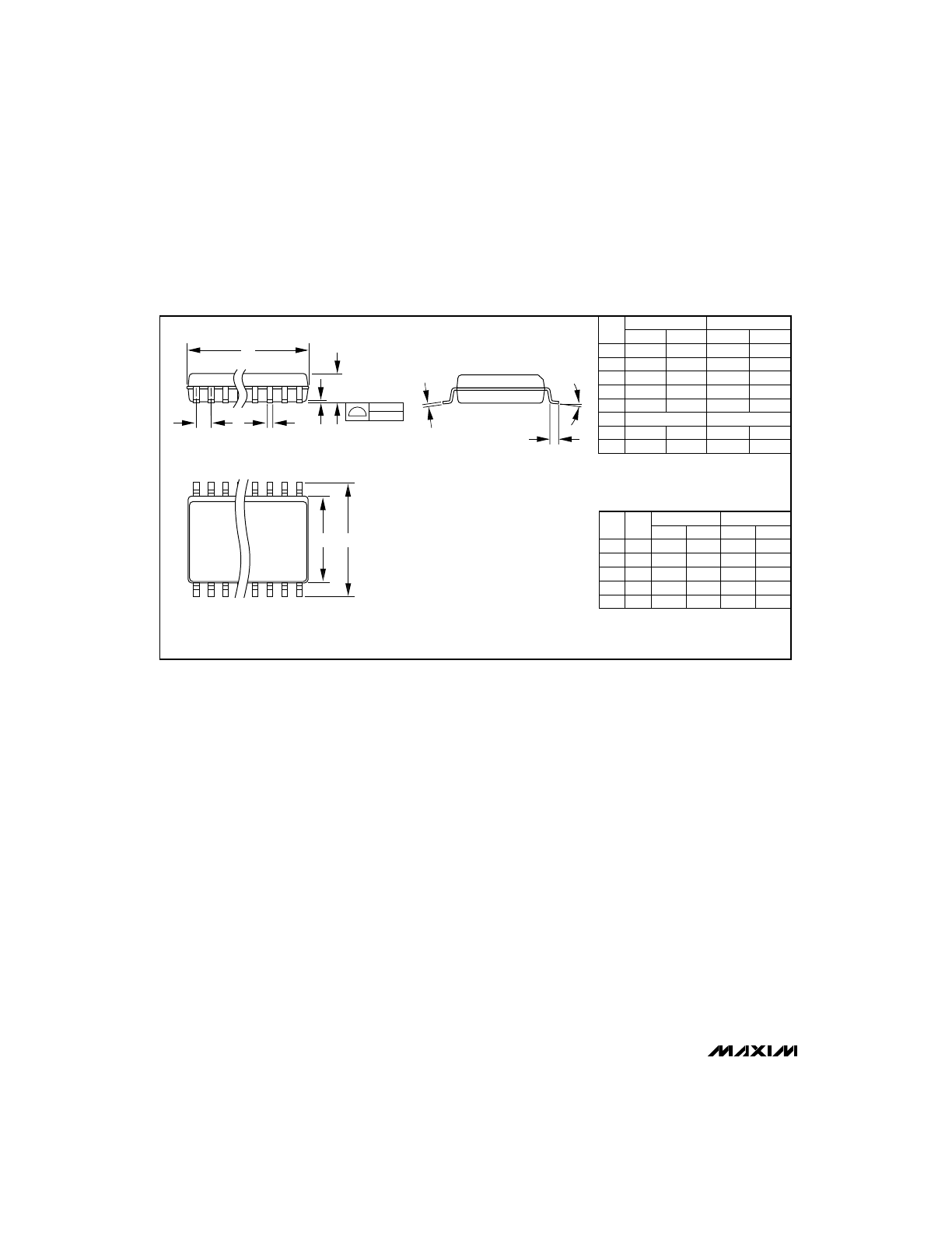
___________________________________________Package Information (continued)
DIM
A
A1
B
C
E
e
H
L
MIN
0.093
0.004
0.014
0.009
0.291
0.394
0.016
MAX
0.104
0.012
0.019
0.013
0.299
0.419
0.050
MIN
2.35
0.10
0.35
0.23
7.40
10.00
0.40
MAX
2.65
0.30
0.49
0.32
7.60
10.65
1.27
INCHES
MILLIMETERS
21-0042A
Wide SO
SMALL-OUTLINE
PACKAGE
(0.300 in.)
DIM
D
D
D
D
D
MIN
0.398
0.447
0.496
0.598
0.697
MAX
0.413
0.463
0.512
0.614
0.713
MIN
10.10
11.35
12.60
15.20
17.70
MAX
10.50
11.75
13.00
15.60
18.10
INCHES
MILLIMETERS
PINS
16
18
20
24
28
1.27
0.050
L
H
E
D
e
A
A1
C
0°- 8°
0.101mm
0.004in.
B