

Standard Power
Data Sheet
Rev 1.0, 2012-09-01
ITS4200S-SJ-D
Smart High-Side NMOS-Power Switch
PG-DSO-8
Data Sheet
2
Rev 1.0, 2012-09-01
Smart High-Side NMOS-Power Switch
ITS4200S-SJ-D
Type
Package
Marking
ITS4200S-SJ-D
PG-DSO-8
I200SD
1
Overview
Features
•
CMOS compatible input
•
Switching all types of resistive, inductive and capacitive loads
•
Fast demagnetization of inductive loads
•
Very low standby current
•
Optimized Electromagnetic Compatibility (EMC)
•
Open drain diagnostic output for overtemperature and short circuit
•
Open load detection in OFF-state with external resistor
•
Overload protection
•
Current limitation
•
Short circuit protection
•
Thermal shutdown with restart
•
Overvoltage protection (including load dump)
•
Reverse battery protection with external resistor
•
Loss of GND and loss of Vbb protection
•
Electrostatic Discharge Protection (ESD)
•
Green Product (RoHS compliant)
ITS4200S-SJ-D is not qualified and manufactured according to the requirements of Infineon Technologies with
regards to automotive and/or transportation applications.
Description
The ITS4200S-SJ-D is a protected 200m Ω single channel Smart High-Side NMOS-Power Switch in a PG-DSO-
8 package with charge pump, CMOS compatible input and diagnostic feedback.
Product Summary
Overvoltage protection
V
SAZmin
= 62V
Operating voltage range: 6V <
V
S
< 52V
On-state resistance
R
DSON
= typ 150mΩ
Nominal load current
I
LNOM
= 1.2A
Operating Temperature range:
T
j
= -40°C to 125°C
Application
•
All types of resistive, inductive and capacitive loads
•
Power switch for 12V, 24V and 45V DC applications with CMOS compatible control interface
•
Open drain diagnosis feedback for overtemperature and short circuit
•
Driver for electromagnetic relays
•
Power managment for high-side-switching with low current consumption in OFF-mode
Data Sheet
3
Rev 1.0, 2012-09-01
ITS4200S-SJ-D
Block Diagram and Terms
2
Block Diagram and Terms
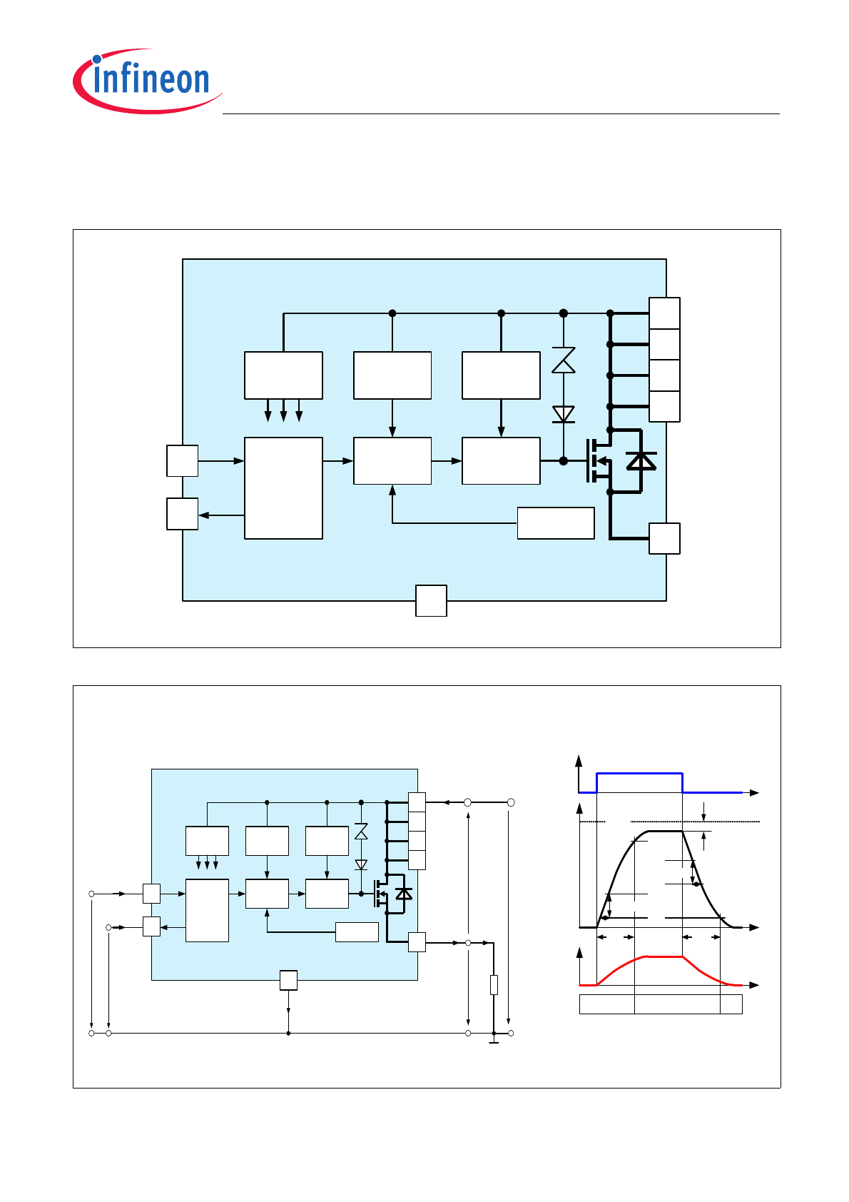
Figure 1
Block diagram
Figure 2
Terms - parameter definition
3
ITS4200S-SJ-D
4
Gate
Control
Circuit
7
Temperature
Sensor
IN
OUT
VS
6
5
8
Bias
Supervision
Overvoltage
Protection
ESD
Protection
Logic
Current
Limiter
2
1
ST
GND
V
ST
V
OU
T
V
S
I
S
I
L
R
L
V
FD
S
GND
Voltage- and Current-Definitions:
Switching Times and Slew Rate Definitions:
OFF
OFF
ON
V
DS
V
OUT
90%
0
+V
S
10%
t
OFF
t
I
L
t
0
t
ON
dV/t
ON
30%
dV/t
OFF
70%
40%
t
3
ITS4200S-SJ-D
4
Gate
Control
Circuit
7
Temperature
Sensor
IN
OUT
VS
6
5
8
Bias
Supervision
Overvoltage
Protection
ESD
Protection
Logic
Current
Limiter
2
1
ST
GND
I
ST
V
IN
I
IN
I
OUT
V
IN
L
H
Data Sheet
4
Rev 1.0, 2012-09-01
ITS4200S-SJ-D
Pin Configuration
3
Pin Configuration
3.1
Pin Assignment
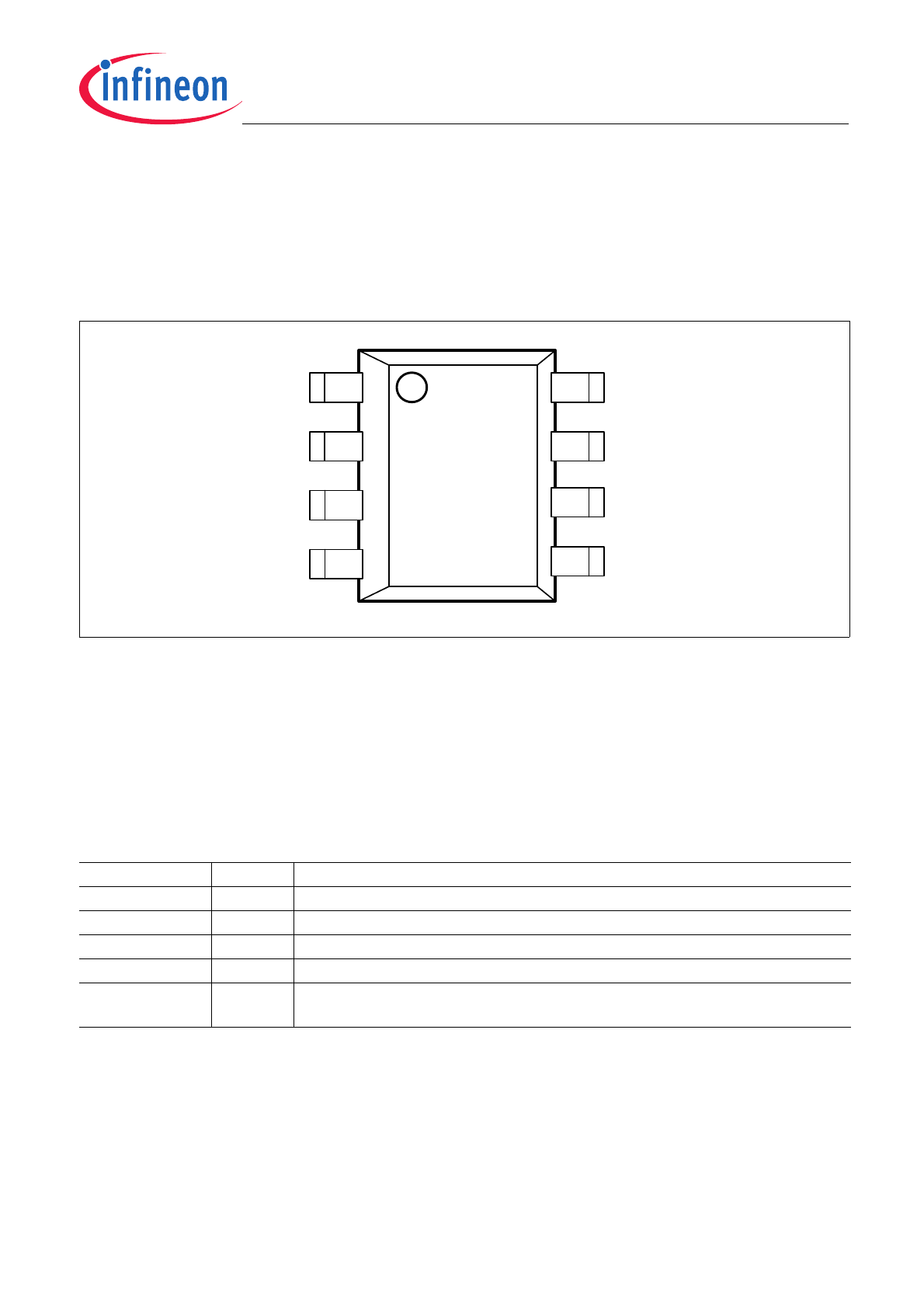
Figure 3
Pin configuration top view, PG-DSO-8
3.2
Pin Definitions and Functions
Pin
Symbol
Function
1
GND
Logic ground
2
IN
Input, controles the power switch; the powerswitch is ON when high
3
OUT
Output to the load
4
ST
Status flag; diagnosis feedback; NMOS open drain
5, 6, 7, 8
VS
Supply voltage (design the wiring for the maximum short circuit current and also
for low thermal resistance)
VS
IN
ST
GND
VS
OUT
VS
VS
8
5
6
7
1
4
3
2
P-DSO-8

Data Sheet
5
Rev 1.0, 2012-09-01
ITS4200S-SJ-D
General Product Characteristics
4
General Product Characteristics
4.1
Absolute Maximum Ratings
Note: Exposure to absolute maximum rating conditions for extended periods may affect device reliability.
Integrated protection functions are designed to prevent IC destruction under fault conditions described in the
data sheet. Fault conditions are considered as “outside” the normal operating range. Protection functions
are neither designed for continuous nor repetitive operation.
Table 1
Absolute maximum ratings
1)
at
T
j
= 25°C unless otherwise specified. Currents flowing into the
device unless otherwise specified in chapter “Block Diagram and Terms”
1) Not subject to production test, specified by design
Parameter
Symbol
Values
Unit
Note /
Test Condit
ion
Number
Min.
Typ.
Max.
Supply voltage VS
Voltage
V
S
52
V
4.1.1
Voltage for short circuit protection
V
SSC
36
V
4.1.2
Output stage OUT
Output Current; (Short circuit current see
electrical characteristics)
I
OUT
self
limited
A
4.1.3
Input IN
Current
I
IN
-5
5
mA
4.1.4
Status ST
Current
I
ST
-5
5
mA
4.1.5
Temperatures
Junction Temperature
T
j
-40
125
°C
4.1.6
Storage Temperature
T
stg
-55
125
°C
4.1.7
Power dissipation
Ta = 25 °C
2)
2) Device on 50mm*50mm*1.5mm epoxy PCB FR4 with 6 cm2 (one layer, 70mm thick) copper area for Vbb connection. PCB
is vertical without blown air
P
tot
1.4
W
4.1.8
Inductive load switch-off energy dissipation
Tj = 125 °C; IL= 1A
3)
3) Not subject to production test, specified by design
E
AS
125
mJ
single pulse 4.1.9
ESD Susceptibility
ESD susceptibility (input pin)
V
ESD
-1
1
kV
HBM
4)
4) ESD susceptibility HBM according to EIA/JESD 22-A 114.
4.1.10
ESD susceptibility (all other pins)
V
ESD
-5
5
kV
HBM
5)
5) ESD susceptibility HBM according to EIA/JESD 22-A 114.
4.1.11

Data Sheet
6
Rev 1.0, 2012-09-01
ITS4200S-SJ-D
General Product Characteristics
4.2
Functional Range
Note: Within the functional range the IC operates as described in the circuit description. The electrical
characteristics are specified within the conditions given in the related electrical characteristics table.
4.3
Thermal Resistance
Note: This thermal data was generated in accordance with JEDEC JESD51 standards. For more information, go
to
www.jedec.org
.
Table 2
Funtional Range
Parameter
Symbol
Values
Unit
Note /
Test Condition
Number
Min.
Typ.
Max.
Nominal Operating Voltage
V
S
6
52
V
V
S
increasing
4.2.1
Table 3
Thermal Resistance
1)
1) Not subject to production test, specified by design
Parameter
Symbol
Values
Unit Note /
Test Condition
Number
Min.
Typ.
Max.
Thermal Resistance - Junction to
pin5
R
thj-pin5
23.3
K/W
4.3.1
Thermal Resistance - Junction to
Ambient - 1s0p, minimal footprint
R
thJA_1s0p
128.7
K/W
2)
2) Specified
R
thJA
value is according to Jedec JESD51-3 at natural convection on FR4 1s0p board, footprint; the Product
(Chip+Package) was simulated on a 76.2 x 114.3 x 1.5 mm board with 1x 70µm Cu.
4.3.2
Thermal Resistance - Junction to
Ambient - 1s0p, 300mm
2
R
thJA_1s0p_300mm
70.1
K/W
3)
3) Specified
R
thJA
value is according to Jedec JESD51-3 at natural convection on FR4 1s0p board, Cu, 300mm
2
; the Product
(Chip+Package) was simulated on a 76.2 x 114.3 x 1.5 mm board with 1x 70µm Cu.
4.3.3
Thermal Resistance - Junction to
Ambient - 1s0p, 600mm
2
R
thJA_1s0p_600mm
65.6
K/W
4)
4) Specified
R
thJA
value is according to Jedec JESD51-3 at natural convection on FR4 1s0p board, 600mm
2
; the Product
(Chip+Package) was simulated on a 76.2 x 114.3 x 1.5 mm board with 1x 70µm Cu.
4.3.4
Thermal Resistance - Junction to
Ambient - 2s2p
R
thJA_2s2p
55.4
K/W
5)
5) Specified
R
thJA
value is according to Jedec JESD51-2,-5,-7 at natural convection on FR4 2s2p board; the Product
(Chip+Package) was simulated on a 76.2 x 114.3 x 1.5 mm board with 2 inner copper layers (2 x 70µm Cu, 2 x 35µm Cu).
4.3.5
Thermal Resistance - Junction to
Ambient with thermal vias - 2s2p
R
thJA_2s2p
53.5
K/W
6)
6) Specified
R
thJA
value is according to Jedec JESD51-2,-5,-7 at natural convection on FR4 2s2p board with two thermal vias;
the Product (Chip+Package) was simulated on a 76.2 x 114.3 x 1.5 mm board with 2 inner copper layers (2 x 70µm Cu, 2
x 35µm Cu. The diameter of the two vias are equal 0.3mm and have a plating of 25um with a copper heatsink area of 3mm
x 2mm). JEDEC51-7: The two plated-through hole vias should have a solder land of no less than 1.25 mm diameter with a
drill hole of no less than 0.85 mm diameter.
4.3.6

Data Sheet
7
Rev 1.0, 2012-09-01
ITS4200S-SJ-D
Electrical Characteristics
5
Electrical Characteristics
Table 4
V
S
= 12V to 42V;
T
j
= -40°C to 125°C; all voltages with respect to ground, currents flowing into
the device unless otherwise specified in chapter “Block Diagram and Terms”. Typical values
at
V
s
= 13.5V,
T
j
= 25°C
Parameter
Symbol
Values
Unit
Note /
Test Condition
Number
Min.
Typ.
Max.
Powerstage
NMOS ON Resistance
R
DSON
150
200
mΩ
I
OUT
= 1A;
T
j
= 25°C;
9V <
V
S
< 52V;
V
IN
= 5V
5.0.1
NMOS ON Resistance
R
DSON
250
350
mΩ
I
OUT
= 1A;
T
j
= 125°C;
9V <
V
S
< 52V;
V
IN
= 5V
5.0.2
Nominal Load Current;
device on PCB
1)
I
LNOM
1.2
A
T
pin5
= 85°C
5.0.3
Timings of Power Stages
2)
Turn ON Time(to 90% of
V
out
);
V
S
to GND transition of
V
IN
t
ON
80
180
µs
V
S
=13.5V;
R
L
= 47Ω
5.0.4
Turn OFF Time (to 10% of
V
out
);
V
S
to GND transition of
V
IN
t
OFF
80
200
µs
V
S
=13.5V;
R
L
= 47Ω
5.0.5
ON-Slew Rate (10 to 30% of
V
out
);
L to H transition of
V
IN
SR
ON
0.7
2.0
V / µs
V
S
=13.5V;
R
L
= 47Ω
5.0.6
OFF-Slew Rate;
dV
OUT
/ dt
ON
(70 to 40% of
V
out
);
H to L transition of
V
IN
SR
OFF
0.9
2.0
V / µs
V
S
=13.5V;
R
L
= 47Ω
5.0.7
Under voltage lockout (charge pump start-stop-restart)
Supply undervoltage;
charge pump stop voltage
V
SUV
4
V
V
S
decreasing
-40°C <
T
j
< 85°C
5.0.8
Supply undervoltage;
Charge pump stop voltage
V
SUV
5.5
V
V
S
decreasing
T
j
= 125°C
5.0.9
Supply startup voltage;
Charge pump restart voltage
V
SSU
4
5.5
V
V
S
increasing
5.0.10
Current consumption
Operating current
I
GND
0.8
2
mA
V
IN
= 5V
5.0.11
Standby current
I
SSTB
15
µA
V
IN
= 0V;
V
OUT
= 0V
-40°C <
T
j
< 85°C
5.0.12
Standby current
I
SSTB
18
µA
V
IN
= 0V;
T
j
= 125°C
5.0.13
Output leakage current
I
OUTLK
5
µA
V
IN
= 0V;
V
OUT
= 0V
5.0.14
Protection functions
3)
Initial peak short circuit current limit
I
LSCP
9
A
T
j
= -40°C
; V
S
= 20V
;
V
IN
= 5.0V;
t
m
= 150µs
5.0.15
Initial peak short circuit current limit
I
LSCP
6.5
A
T
j
= 25°C
; V
S
= 20V;
V
IN
= 5.0V;
t
m
= 150µs
5.0.16

Data Sheet
8
Rev 1.0, 2012-09-01
ITS4200S-SJ-D
Electrical Characteristics
Initial peak short circuit current limit
I
LSCP
4
A
T
j
=125°C
; V
S
= 20V;
V
IN
= 5.0V;
t
m
= 150µs
5.0.17
Initial peak short circuit current limit
4)
I
LSCP
5
A
V
S
> 40V;
V
IN
= 5.0V;
t
m
= 150µs
5.0.18
Repetitive short circuit current limit
T
j
=
T
jTrip
; see timing diagrams
I
LSCR
6
A
V
IN
= 5.0V;
V
S
< 40V
5.0.19
Repetitive short circuit current limit
T
j
=
T
jTrip
; see timing diagrams
I
LSCR
4.5
A
V
IN
= 5.0V;
V
S
> 40V
5.0.20
Output clamp at
V
OUT
=
V
S
-
V
DSCL
(inductive load switch off)
V
DSCL
59
63
V
I
S
= 4mA
5.0.22
Overvoltage protection
V
OUT
=
V
S
-
V
ONCL
V
SAZ
62
V
I
S
= 4mA
5.0.23
Thermal overload
trip temperature
T
jTrip
150
°C
5.0.24
Thermal hysteresis
T
HYS
10
K
5.0.25
Reverse Battery
5)
Continuous reverse battery voltage
V
SREV
52
V
5.0.26
Forward voltage of the drain-source
reverse diode
V
FDS
600
mV
I
FDS
= 200mA;
V
IN
= 0V;
T
j
= 125°C
5.0.27
Input interface; pin IN
Input turn-ON threshold voltage
V
INON
2.2
V
5.0.28
Input turn-OFF threshold voltage
V
INOFF
0.8
V
5.0.29
Input threshold hysteresis
V
INHYS
0.4
V
5.0.30
Off state input current
I
INOFF
1
25
µA
V
IN
= 0.7V
5.0.31
On state input current
I
INON
3
25
µA
V
IN
= 5.0V
5.0.32
Input resistance
R
IN
2.0
3.5
5.0
kΩ
5.0.33
Status output (NMOS open drain); pin ST
Status output zener voltage
V
STZ
5.4
6.1
6.8
V
I
ST
= 1.6mA
5.0.34
Status output low voltage
V
STLO
0.4
V
I
ST
= 1.6mA
;T
j
< 25°C 5.0.35
Status output low voltage
V
STLO
0.6
V
I
ST
= 1.6mA
T
j
< 125°C
5.0.36
Status leakage current
I
STLK
2
µA
V
ST
= 5V;
T
j
< 105°C
5.0.37
Status invalid time after positive input
slope
6)7)
t
dP
120
160
µs
V
S
= 13.5V
5.0.38
Status invalid time after negative input
slope
8)9)
t
dN
250
400
µs
V
S
= 13.5V
5.0.39
Diagnostic characteristics
Short circuit detection voltage
V
OUTSC
2.8
V
5.0.40
Open load detection voltage
10)
V
OUTOL
3
4
V
5.0.41
Internal pull down resistor
11)
R
OUTPD
200
kΩ
V
OUT
= 4V
5.0.42
Table 4
V
S
= 12V to 42V;
T
j
= -40°C to 125°C; all voltages with respect to ground, currents flowing into
the device unless otherwise specified in chapter “Block Diagram and Terms”. Typical values
at
V
s
= 13.5V,
T
j
= 25°C
Parameter
Symbol
Values
Unit
Note /
Test Condition
Number
Min.
Typ.
Max.

Data Sheet
9
Rev 1.0, 2012-09-01
ITS4200S-SJ-D
Electrical Characteristics
1) Device on 50mm x 50mm x 1,5mm epoxy FR4 PCB with 6cm² (one layer copper 70um thick) copper area for supply voltage
connection. PCB in vertical position without blown air.
2) Timing values only with high slewrate input signal; otherwise slower.
3) Integrated protection functions are designed to prevent IC destruction under fault conditions described in the data sheet.
Fault conditions are considered as “outside” normal operating range. Protection functions are not designed for continuous
repetitive operation.
4) No subject to production test; specified by design.
5) Requires a 150W resistor in GND connection. The reverse load current trough the intrinsic drain-source diode of the power-
MOS has to be limited by the connected load. Power dissipation is higher compared to normal operation due to the votage
drop across the drain-source diode. The temperature protection is not functional during reverse current operation! Input
current has to be limited (see max ratings).
6) No delay time after overtemparature switch off and short circuit in on-state.
7) No subject to production test; specified by design.
8) No delay time after overtemparature switch off and short circuit in on-state.
9) No subject to production test; specified by design.
10) External pull up resistor required for open load detection in off state.
11) No subject to production test; specified by design.
Data Sheet
10
Rev 1.0, 2012-09-01
ITS4200S-SJ-D
Typical Performance Graphs
6
Typical Performance Graphs
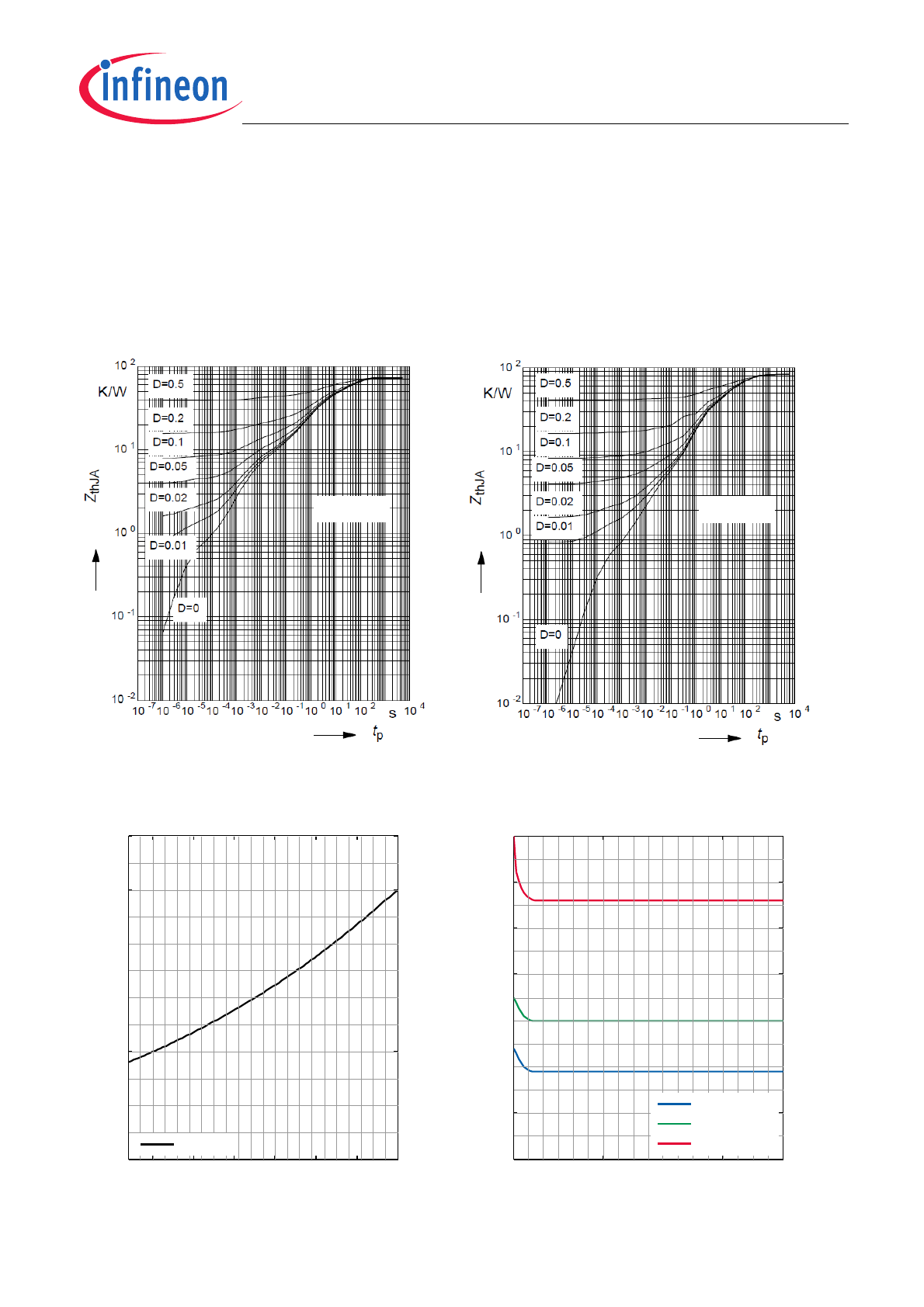
Typical Characterisitics
Transient Thermal Impedance Z
thJA
versus
Pulse Time
t
p
@ 6cm² heatsink area
Transient Thermal Impedance Z
thJA
versus
Pulse Time
t
p
@ min footprint
On-Resistance
R
DSON
versus
Junction Temperature
T
j
On-Resistance
R
DSON
versus
Supply Voltage
V
S
D = t
p
/ T
D = t
p
/ T
−40 −25
0
25
50
75
100
125
0
50
100
150
200
250
300
T
j
[
°
C]
R
DSON
[m
Ω
]
V
s
=13.5V
10
20
30
40
50
0
50
100
150
200
250
300
350
V
s
[V]
R
DSON
[m
Ω
]
T
j
=−40
°
C;I
L
=1A
T
j
=25
°
C;I
L
=1A
T
j
=125
°
C;I
L
=1A