

Technische Information / Technical Information
IGBT-Module
IGBT-Modules
FP15R12KS4C
Elektrische Eigenschaften / Electrical properties
Höchstzulässige Werte / Maximum rated values
Diode Gleichrichter/ Diode Rectifier
Periodische Rückw. Spitzensperrspannung
repetitive peak reverse voltage
V
RRM
1600
V
Durchlaßstrom Grenzeffektivwert
RMS forward current per chip
I
FRMSM
40
A
Dauergleichstrom
DC forward current
T
C
= 80°C
I
d
15
A
Stoßstrom Grenzwert
t
P
= 10 ms, T
vj
= 25°C
I
FSM
300
A
surge forward current
t
P
= 10 ms, T
vj
= 150°C
230
A
Grenzlastintegral
t
P
= 10 ms, T
vj
= 25°C
I
2
t
450
A
2
s
I
2
t - value
t
P
= 10 ms, T
vj
= 150°C
260
A
2
s
Transistor Wechselrichter/ Transistor Inverter
Kollektor-Emitter-Sperrspannung
collector-emitter voltage
V
CES
1200
V
Kollektor-Dauergleichstrom
Tc = 80 °C
I
C,nom.
15
A
DC-collector current
T
C
= 25 °C
I
C
30
A
Periodischer Kollektor Spitzenstrom
repetitive peak collector current
t
P
= 1 ms, T
C
=
80 °C
I
CRM
30
A
Gesamt-Verlustleistung
total power dissipation
T
C
= 25°C
P
tot
180
W
Gate-Emitter-Spitzenspannung
gate-emitter peak voltage
V
GES
+/- 20V
V
Diode Wechselrichter/ Diode Inverter
Dauergleichstrom
DC forward current
Tc = 80 °C
I
F
15
A
Periodischer Spitzenstrom
repetitive peak forw. current
t
P
= 1 ms
I
FRM
30
A
Grenzlastintegral
I
2
t - value
V
R
= 0V, t
p
= 10ms, T
vj
= 125°C
I
2
t
125
A
2
s
Transistor Brems-Chopper/ Transistor Brake-Chopper
Kollektor-Emitter-Sperrspannung
collector-emitter voltage
V
CES
1200
V
Kollektor-Dauergleichstrom
T
C
= 80 °C
I
C,nom.
10
A
DC-collector current
T
C
= 25 °C
I
C
20
A
Periodischer Kollektor Spitzenstrom
repetitive peak collector current
t
P
= 1 ms, T
C
= 80°C
I
CRM
20
A
Gesamt-Verlustleistung
total power dissipation
T
C
= 25°C
P
tot
100
W
Gate-Emitter-Spitzenspannung
gate-emitter peak voltage
V
GES
+/- 20V
V
Diode Brems-Chopper/ Diode Brake-Chopper
Dauergleichstrom
DC forward current
Tc = 80 °C
I
F
10
A
Periodischer Spitzenstrom
repetitive peak forw. current
t
P
= 1 ms
I
FRM
20
A
prepared by: A.Schulz
date of publication: 2001-11-28
approved by: M.Hierholzer
revision: 2
1/11
DB-PIM-S_IGBT_V2.xls
2001-11-28

Technische Information / Technical Information
IGBT-Module
IGBT-Modules
FP15R12KS4C
Modul Isolation/ Module Isolation
Isolations-Prüfspannung
insulation test voltage
RMS, f = 50 Hz, t = 1 min.
NTC connected to Baseplate
V
ISOL
2,5
kV
Elektrische Eigenschaften / Electrical properties
Charakteristische Werte / Characteristic values
Diode Gleichrichter/ Diode Rectifier
min.
typ.
max.
Durchlaßspannung
forward voltage
T
vj
= 150°C, I
F
=
15 A
V
F
-
0,95
-
V
Schleusenspannung
threshold voltage
T
vj
= 150°C
V
(TO)
-
-
0,8
V
Ersatzwiderstand
slope resistance
T
vj
= 150°C
r
T
-
-
10,5
m
Ω
Sperrstrom
reverse current
T
vj
= 150°C, V
R
=
1600 V
I
R
-
2
-
mA
Modul Leitungswiderstand, Anschlüsse-Chip
lead resistance, terminals-chip
T
C
= 25°C
R
AA'+CC'
-
8
-
m
Ω
Transistor Wechselrichter/ Transistor Inverter
min.
typ.
max.
Kollektor-Emitter Sättigungsspannung
V
GE
= 15V, T
vj
= 25°C, I
C
=
15 A
V
CE sat
-
3,2
3,7
V
collector-emitter saturation voltage
V
GE
= 15V, T
vj
= 125°C, I
C
=
15 A
-
3,85
-
V
Gate-Schwellenspannung
gate threshold voltage
V
CE
= V
GE
, T
vj
= 25°C, I
C
=
0,6 mA
V
GE(TO)
4,5
5,5
6,5
V
Eingangskapazität
input capacitance
f = 1MHz, T
vj
= 25°C
V
CE
= 25 V, V
GE
= 0 V
C
ies
-
1,0
-
nF
Kollektor-Emitter Reststrom
collector-emitter cut-off current
Gate-Emitter Reststrom
gate-emitter leakage current
V
CE
= 0V, V
GE
=20V, T
vj
=25°C
I
GES
-
-
400
nA
Einschaltverzögerungszeit (ind. Last)
I
C
= I
Nenn
, V
CC
=
600 V
turn on delay time (inductive load)
V
GE
= ±15V, T
vj
= 25°C, R
G
=
47 Ohm
t
d,on
-
60
-
ns
V
GE
= ±15V, T
vj
= 125°C, R
G
=
47 Ohm
-
60
-
ns
Anstiegszeit (induktive Last)
I
C
= I
Nenn
, V
CC
=
600 V
rise time (inductive load)
V
GE
= ±15V, T
vj
= 25°C, R
G
=
47 Ohm
t
r
-
50
-
ns
V
GE
= ±15V, T
vj
= 125°C, R
G
=
47 Ohm
-
50
-
ns
Abschaltverzögerungszeit (ind. Last)
I
C
= I
Nenn
, V
CC
=
600 V
turn off delay time (inductive load)
V
GE
= ±15V, T
vj
= 25°C, R
G
=
47 Ohm
t
d,off
-
340
-
ns
V
GE
= ±15V, T
vj
= 125°C, R
G
=
47 Ohm
-
400
-
ns
Fallzeit (induktive Last)
I
C
= I
Nenn
, V
CC
=
600 V
fall time (inductive load)
V
GE
= ±15V, T
vj
= 25°C, R
G
=
47 Ohm
t
f
-
50
-
ns
V
GE
= ±15V, T
vj
= 125°C, R
G
=
47 Ohm
-
60
-
ns
Einschaltverlustenergie pro Puls
I
C
= I
Nenn
, V
CC
=
600 V
turn-on energy loss per pulse
V
GE
= ±15V, T
vj
= 125°C, R
G
=
47 Ohm
E
on
-
2
-
mWs
L
S
=
75 nH
Abschaltverlustenergie pro Puls
I
C
= I
Nenn
, V
CC
=
600 V
turn-off energy loss per pulse
V
GE
= ±15V, T
vj
= 125°C, R
G
=
47 Ohm
E
off
-
1
-
mWs
L
S
=
75 nH
Kurzschlußverhalten
t
P
≤
10µs, V
GE
≤
15V, R
G
=
47 Ohm
SC Data
T
vj
≤
125°C, V
CC
=
720 V
I
SC
-
90
-
A
dI/dt =
1200 A/µs
mA
-
-
V
GE
= 0V, T
vj
= 25°C, V
CE
=
1200 V
I
CES
5
2/11
DB-PIM-S_IGBT_V2.xls
2001-11-28

Technische Information / Technical Information
IGBT-Module
IGBT-Modules
FP15R12KS4C
Elektrische Eigenschaften / Electrical properties
Charakteristische Werte / Characteristic values
min.
typ.
max.
Modulinduktivität
stray inductance module
L
σ
CE
-
-
100
nH
Modul Leitungswiderstand, Anschlüsse-Chip
lead resistance, terminals-chip
T
C
= 25°C
R
CC'+EE'
-
11
-
m
Ω
Diode Wechselrichter/ Diode Inverter
min.
typ.
max.
Durchlaßspannung
V
GE
= 0V, T
vj
= 25°C, I
F
=
15 A
V
F
-
1,75
2,1
V
forward voltage
V
GE
= 0V, T
vj
= 125°C, I
F
=
15 A
-
1,6
-
V
Rückstromspitze
I
F
=I
Nenn
, - di
F
/dt =
1000A/µs
peak reverse recovery current
V
GE
= -10V, T
vj
= 25°C, V
R
=
600 V
I
RM
-
22
-
A
V
GE
= -10V, T
vj
= 125°C, V
R
=
600 V
-
25
-
A
Sperrverzögerungsladung
I
F
=I
Nenn
, - di
F
/dt =
1000A/µs
recovered charge
V
GE
= -10V, T
vj
= 25°C, V
R
=
600 V
Q
r
-
1,6
-
µAs
V
GE
= -10V, T
vj
= 125°C, V
R
=
600 V
-
3,2
-
µAs
Abschaltenergie pro Puls
I
F
=I
Nenn
, - di
F
/dt =
1000A/µs
reverse recovery energy
V
GE
= -10V, T
vj
= 25°C, V
R
=
600 V
E
RQ
-
0,5
-
mWs
V
GE
= -10V, T
vj
= 125°C, V
R
=
600 V
-
1,2
-
mWs
Transistor Brems-Chopper/ Transistor Brake-Chopper
min.
typ.
max.
Kollektor-Emitter Sättigungsspannung
V
GE
= 15V, T
vj
= 25°C, I
C
=
10,0 A
V
CE sat
-
2,4
2,85
V
collector-emitter saturation voltage
V
GE
= 15V, T
vj
= 125°C, I
C
=
10,0 A
-
2,75
-
V
Gate-Schwellenspannung
gate threshold voltage
V
CE
= V
GE
, T
vj
= 25°C, I
C
=
0,35mA
V
GE(TO)
4,5
5,5
6,5
V
Eingangskapazität
input capacitance
f = 1MHz, T
vj
= 25°C
V
CE
= 25 V, V
GE
= 0 V
C
ies
-
0,6
-
nF
Kollektor-Emitter Reststrom
V
GE
= 0V, T
vj
= 25°C, V
CE
=
1200 V
I
CES
-
0,5
500
µA
collector-emitter cut-off current
V
GE
= 0V, T
vj
= 125°C, V
CE
=
1200 V
-
0,8
-
mA
Gate-Emitter Reststrom
gate-emitter leakage current
V
CE
= 0V, V
GE
= 20V, T
vj
= 25°C
I
GES
-
-
300
nA
Schaltverluste und -bedingungen
Switching losses and conditions
siehe Datenblatt (Wechselrichter)
see datasheet (inverter)
BSM10GP120
Diode Brems-Chopper/ Diode Brake-Chopper
min.
typ.
max.
Durchlaßspannung
T
vj
= 25°C, I
F
=
10,0 A
V
F
-
2,2
2,55
V
forward voltage
T
vj
= 125°C, I
F
=
10,0 A
-
2,1
-
V
Schaltverluste und -bedingungen
Switching losses and conditions
siehe Datenblatt (Wechselrichter)
see datasheet (inverter)
BSM10GP120
NTC-Widerstand/ NTC-Thermistor
min.
typ.
max.
Nennwiderstand
rated resistance
T
C
= 25°C
R
25
-
5
-
k
Ω
Abweichung von R
100
deviation of R
100
T
C
= 100°C, R
100
= 493
Ω
∆
R/R
-5
5
%
Verlustleistung
power dissipation
T
C
= 25°C
P
25
20
mW
B-Wert
B-value
R
2
= R
1
exp [B(1/T
2
- 1/T
1
)]
B
25/50
3375
K
3/11
DB-PIM-S_IGBT_V2.xls
2001-11-28

Technische Information / Technical Information
IGBT-Module
IGBT-Modules
FP15R12KS4C
Thermische Eigenschaften / Thermal properties
min.
typ.
max.
Innerer Wärmewiderstand
Gleichr. Diode/ Rectif. Diode
R
thJC
-
-
1
K/W
thermal resistance, junction to case
Trans. Wechsr./ Trans. Inverter
-
-
0,7
K/W
Diode Wechsr./ Diode Inverter
-
-
1,2
K/W
Trans. Bremse/ Trans. Brake
-
-
1,2
K/W
Diode Bremse/ Diode Brake
-
-
2,3
K/W
Übergangs-Wärmewiderstand
Gleichr. Diode/ Rectif. Diode
λ
Paste
=1W/m*K
R
thCK
-
0,08
-
K/W
thermal resistance, case to heatsink
Trans. Wechsr./ Trans. Inverter
λ
grease
=1W/m*K
-
0,04
-
K/W
Diode Wechsr./ Diode Inverter
-
0,08
-
K/W
Höchstzulässige Sperrschichttemperatur
maximum junction temperature
T
vj max
-
-
150
°C
Betriebstemperatur
operation temperature
T
vj op
-40
-
125
°C
Lagertemperatur
storage temperature
T
stg
-40
-
125
°C
Mechanische Eigenschaften / Mechanical properties
Innere Isolation
internal insulation
Al
2
O
3
CTI
comperative tracking index
225
Anzugsdrehmoment f. mech. Befestigung
M
3
Nm
mounting torque
±10%
Gewicht
weight
G
180
g
4/11
DB-PIM-S_IGBT_V2.xls
2001-11-28
Technische Information / Technical Information
IGBT-Module
IGBT-Modules
FP15R12KS4C
I
C
[A]
V
CE
[V]
I
C
[A]
V
CE
[V]
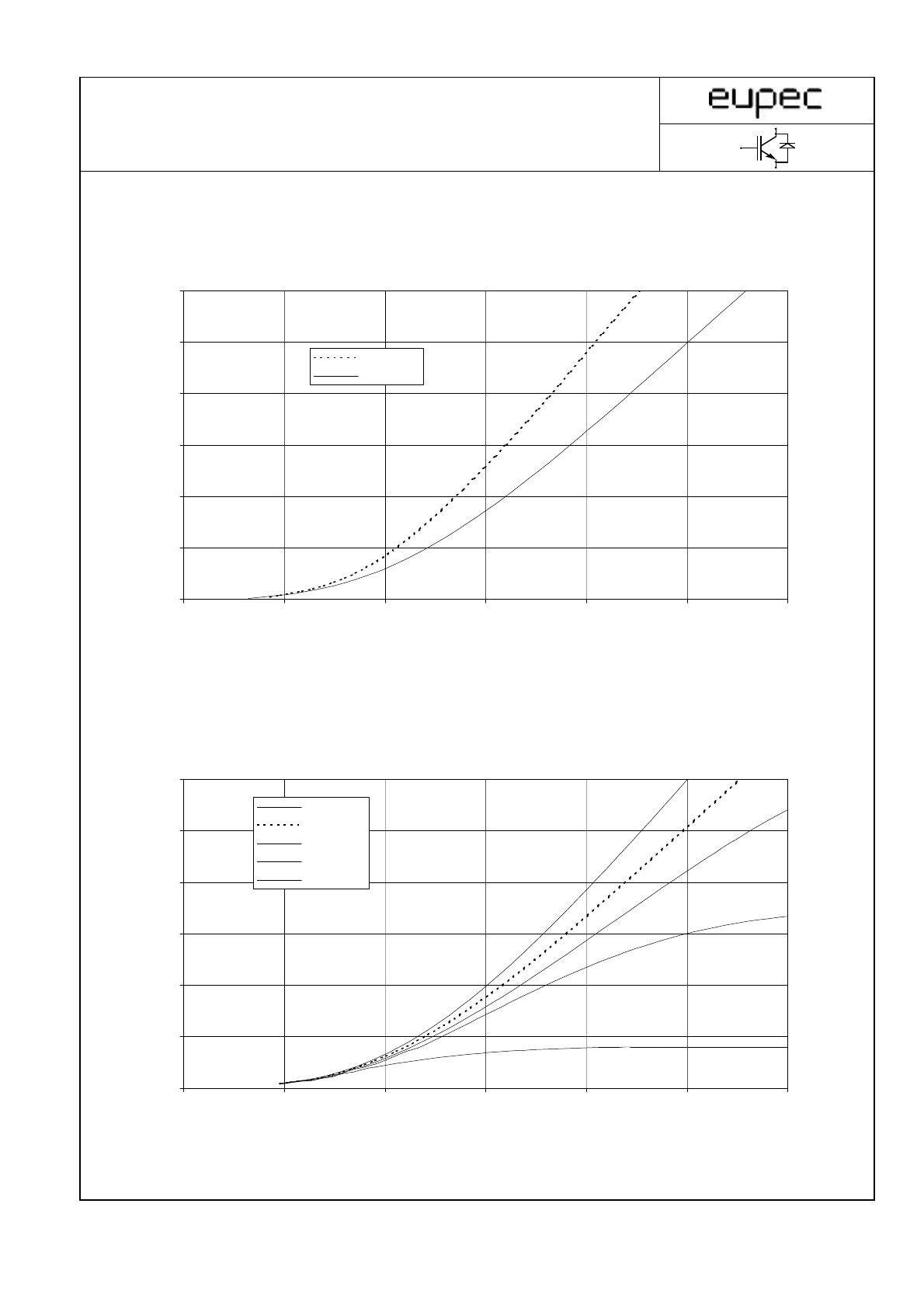
Ausgangskennlinienfeld Wechselr. (typisch) I
C
= f (V
CE
)
Output characteristic Inverter (typical)
V
GE
= 15 V
0
5
10
15
20
25
30
0
1
2
3
4
5
6
Tj = 25°C
Tj = 125°C
0
5
10
15
20
25
30
0
1
2
3
4
5
6
VGE = 20V
VGE = 15V
VGE = 12V
VGE = 10V
VGE = 8V
Ausgangskennlinienfeld Wechselr. (typisch) I
C
= f (V
CE
)
Output characteristic Inverter (typical)
T
vj
= 125°C
5/11
DB-PIM-S_IGBT_V2.xls
2001-11-28
Technische Information / Technical Information
IGBT-Module
IGBT-Modules
FP15R12KS4C
I
C
[A]
V
GE
[V]
I
F
[A]
V
F
[V]
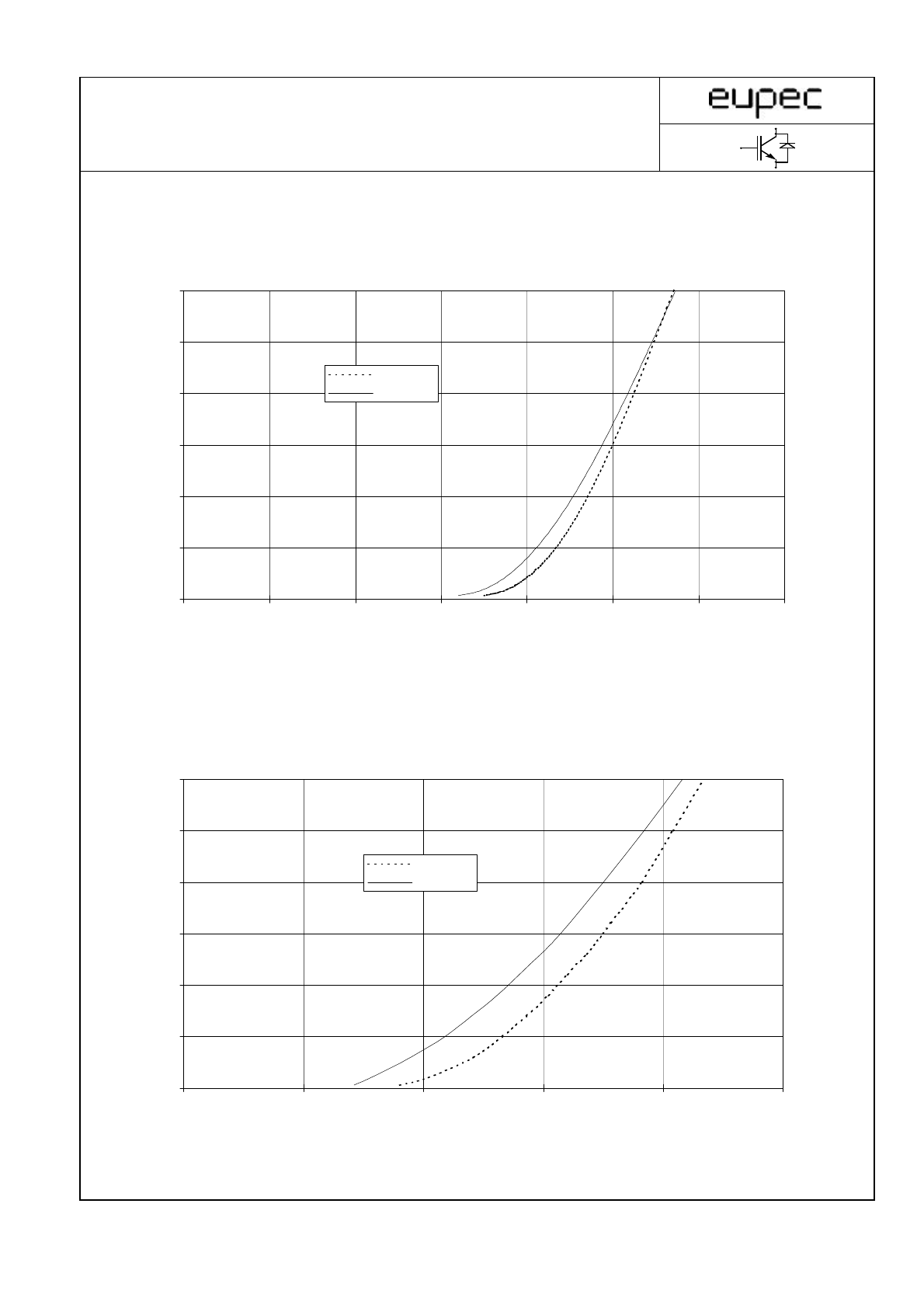
Durchlaßkennlinie der Freilaufdiode Wechselr. (typisch) I
F
= f (V
F
)
Forward characteristic of FWD Inverter (typical)
0
5
10
15
20
25
30
0
2
4
6
8
10
12
14
Tj = 25°C
Tj = 125°C
Übertragungscharakteristik Wechselr. (typisch) I
C
= f (V
GE
)
Transfer characteristic Inverter (typical)
V
CE
= 20 V
0
5
10
15
20
25
30
0
0,5
1
1,5
2
2,5
Tj = 25°C
Tj = 125°C
6/11
DB-PIM-S_IGBT_V2.xls
2001-11-28
Technische Information / Technical Information
IGBT-Module
IGBT-Modules
FP15R12KS4C
600 V
47 Ohm
E [mWs]
I
C
[A]
600 V
E [mWs]
R
G
[
Ω]
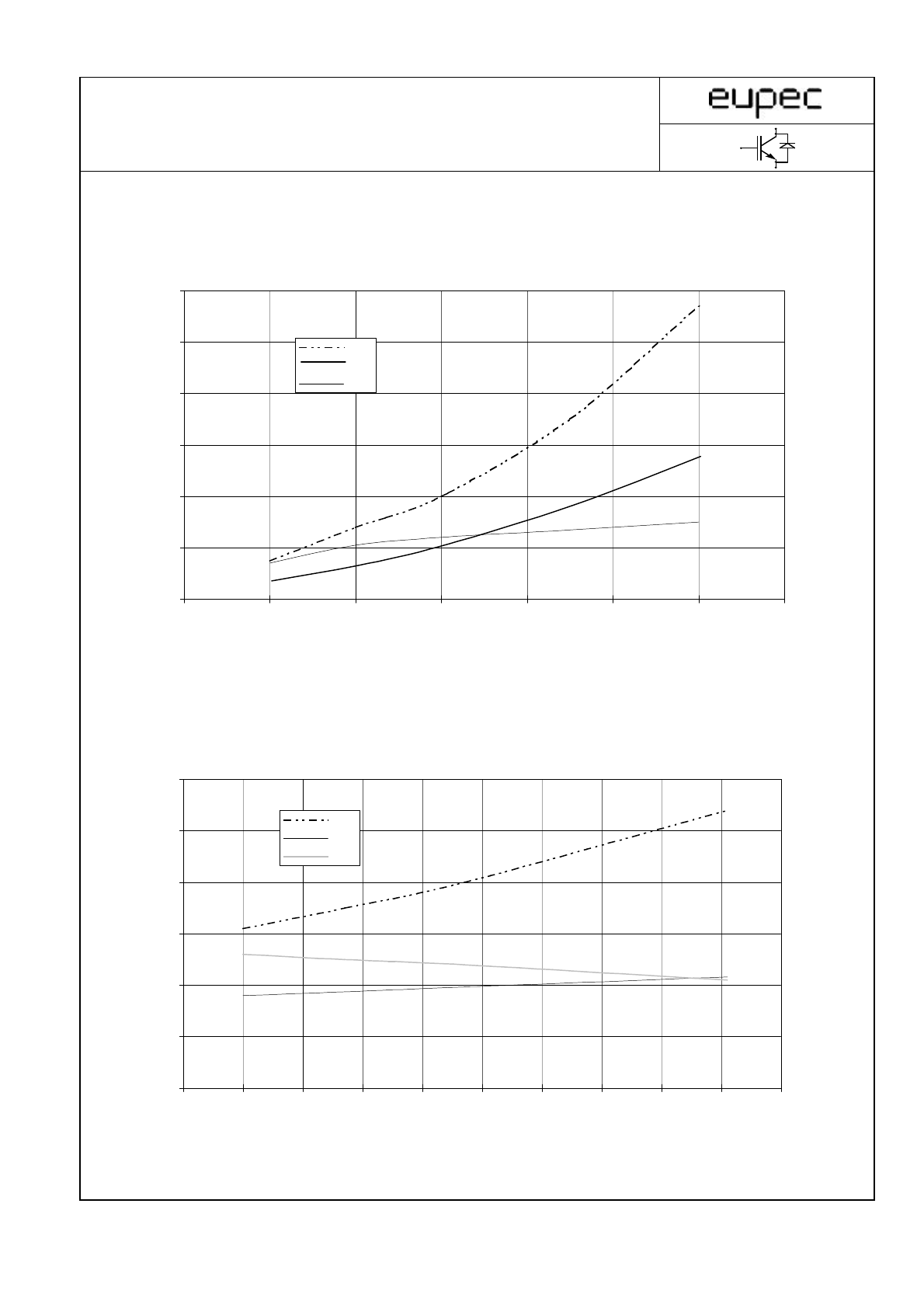
Schaltverluste Wechselr. (typisch) E
on
= f (I
C
), E
off
= f (I
C
), E
rec
= f (I
C
)
V
CC
=
Switching losses Inverter (typical)
T
j
= 125°C, V
GE
= ±15 V, R
Gon
= R
Goff
=
0
1
2
3
4
5
6
0
5
10
15
20
25
30
35
Eon
Eoff
Erec
0
0,5
1
1,5
2
2,5
3
0
10
20
30
40
50
60
70
80
90
100
Eon
Eoff
Erec
Schaltverluste Wechselr. (typisch) E
on
= f (R
G
), E
off
= f (R
G
), E
rec
= f (R
G
)
Switching losses Inverter (typical)
T
j
= 125°C, V
GE
= +-15 V , I
c
= I
nenn
, V
CC
=
7/11
DB-PIM-S_IGBT_V2.xls
2001-11-28
Technische Information / Technical Information
IGBT-Module
IGBT-Modules
FP15R12KS4C
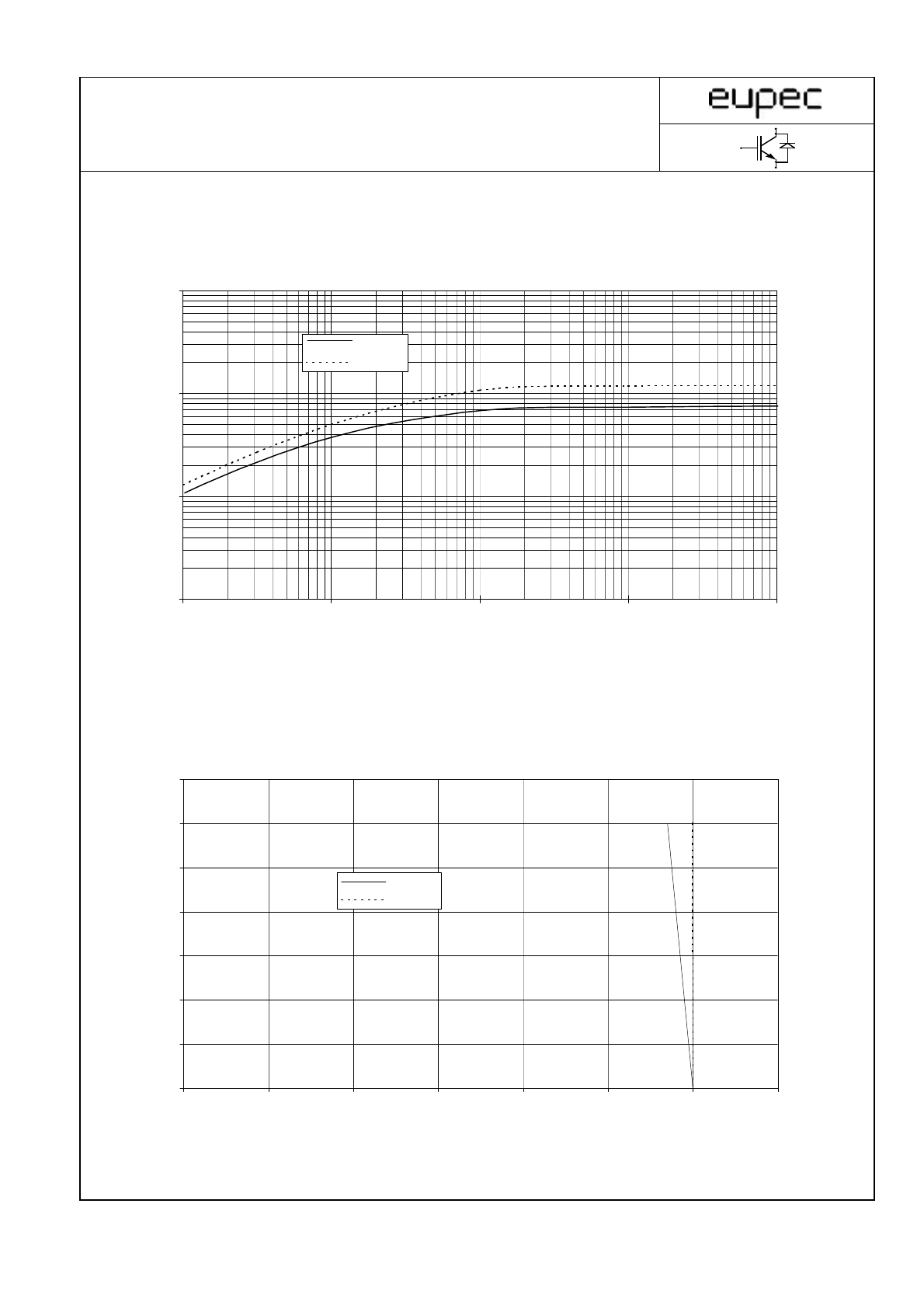
Z
thJC
[K/W]
t [s]
47 Ohm
I
C
[A]
V
CE
[V]
Transienter Wärmewiderstand Wechselr. Z
thJC
= f (t)
Transient thermal impedance Inverter
0,01
0,1
1
10
0,001
0,01
0,1
1
10
Zth-IGBT
Zth-FWD
Sicherer Arbeitsbereich Wechselr. (RBSOA) I
C
= f (V
CE
)
Reverse bias save operating area Inverter (RBSOA)
T
vj
= 125°C, V
GE
= ±15V, R
G
=
0
5
10
15
20
25
30
35
0
200
400
600
800
1000
1200
1400
IC,Modul
IC,Chip
8/11
DB-PIM-S_IGBT_V2.xls
2001-11-28
Technische Information / Technical Information
IGBT-Module
IGBT-Modules
FP15R12KS4C
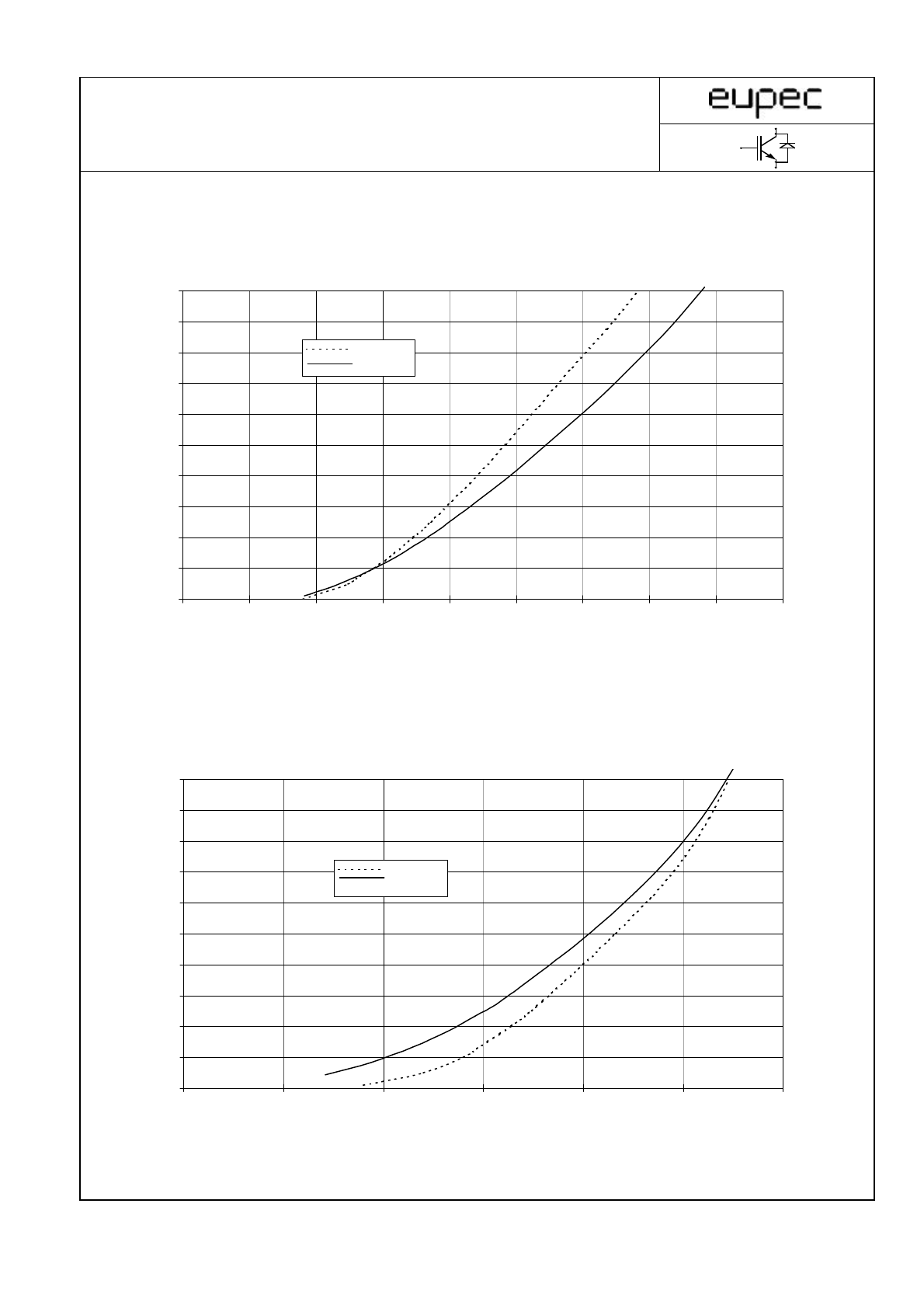
I
C
[A]
V
CE
[V]
I
F
[A]
V
F
[V]
0
2
4
6
8
10
12
14
16
18
20
0
0,5
1
1,5
2
2,5
3
3,5
4
4,5
Tj = 25°C
Tj = 125°C
Durchlaßkennlinie der Brems-Chopper-Diode (typisch) I
F
= f (V
F
)
Forward characteristic of brake-chopper-FWD (typical)
Ausgangskennlinienfeld Brems-Chopper-IGBT (typisch) I
C
= f (V
CE
)
Output characteristic brake-chopper-IGBT (typical)
V
GE
= 15 V
0
2
4
6
8
10
12
14
16
18
20
0
0,5
1
1,5
2
2,5
3
Tj = 25°C
Tj = 125°C
9/11
DB-PIM-S_IGBT_V2.xls
2001-11-28
Technische Information / Technical Information
IGBT-Module
IGBT-Modules
FP15R12KS4C
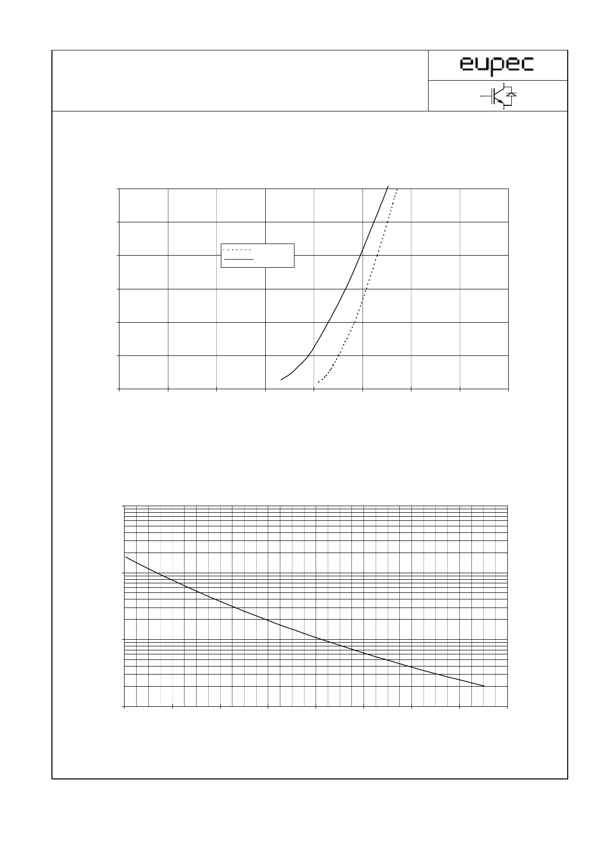
I
F
[A]
V
F
[V]
R[
Ω
]
T
C
[°C]
Durchlaßkennlinie der Gleichrichterdiode (typisch) I
F
= f (V
F
)
Forward characteristic of Rectifier Diode (typical)
0
5
10
15
20
25
30
0
0,2
0,4
0,6
0,8
1
1,2
1,4
1,6
Tj = 25°C
Tj = 150°C
NTC- Temperaturkennlinie (typisch) R = f (T)
NTC- temperature characteristic (typical)
Rtyp
100
1000
10000
100000
0
20
40
60
80
100
120
140
160
10/11
DB-PIM-S_IGBT_V2.xls
2001-11-28