
1
TechnischeInformation/TechnicalInformation
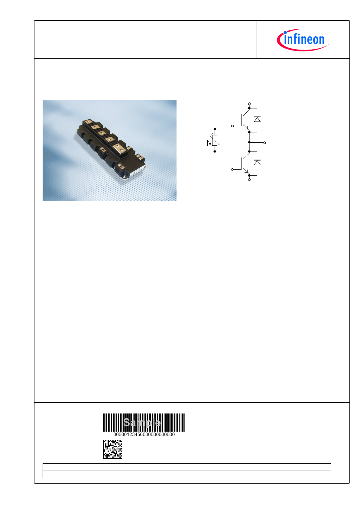
FF1000R17IE4D_B2
IGBT-Module
IGBT-modules
preparedby:TA
approvedby:PL
dateofpublication:2013-11-05
revision:2.1
PrimePACK™3ModulundNTC
PrimePACK™3moduleandNTC
VorläufigeDaten/PreliminaryData
V
CES
= 1700V
I
C nom
= 1000A / I
CRM
= 2000A
TypischeAnwendungen
TypicalApplications
•
•
3-Level-Applikationen
3-Level-Applications
•
•
Hilfsumrichter
AuxiliaryInverters
•
•
Hochleistungsumrichter
HighPowerConverters
•
•
Motorantriebe
MotorDrives
•
•
Traktionsumrichter
TractionDrives
•
•
Windgeneratoren
WindTurbines
ElektrischeEigenschaften
ElectricalFeatures
•
•
ErweiterteSperrschichttemperaturT
vjop
ExtendedOperationTemperatureT
vjop
•
•
GroßeDC-Festigkeit
HighDCStability
•
•
HoheStromdichte
HighCurrentDensity
•
•
NiedrigeSchaltverluste
LowSwitchingLosses
•
•
T
vjop
=150°C
T
vjop
=150°C
•
•
VerstärkteDiodefürRückspeisebetrieb
EnlargedDiodeforregenerativeoperation
•
•
NiedrigesV
CEsat
LowV
CEsat
MechanischeEigenschaften
MechanicalFeatures
•
•
GehäusemitCTI>400
PackagewithCTI>400
•
•
GroßeLuft-undKriechstrecken
HighCreepageandClearanceDistances
•
•
HoheLast-undthermischeWechselfestigkeit
HighPowerandThermalCyclingCapability
•
•
HoheLeistungsdichte
HighPowerDensity
•
•
Kupferbodenplatte
CopperBasePlate
ModuleLabelCode
BarcodeCode128
DMX-Code
ContentoftheCode
Digit
ModuleSerialNumber
1-5
ModuleMaterialNumber
6-11
ProductionOrderNumber
12-19
Datecode(ProductionYear)
20-21
Datecode(ProductionWeek)
22-23
2
TechnischeInformation/TechnicalInformation
FF1000R17IE4D_B2
IGBT-Module
IGBT-modules
preparedby:TA
approvedby:PL
dateofpublication:2013-11-05
revision:2.1
VorläufigeDaten
PreliminaryData
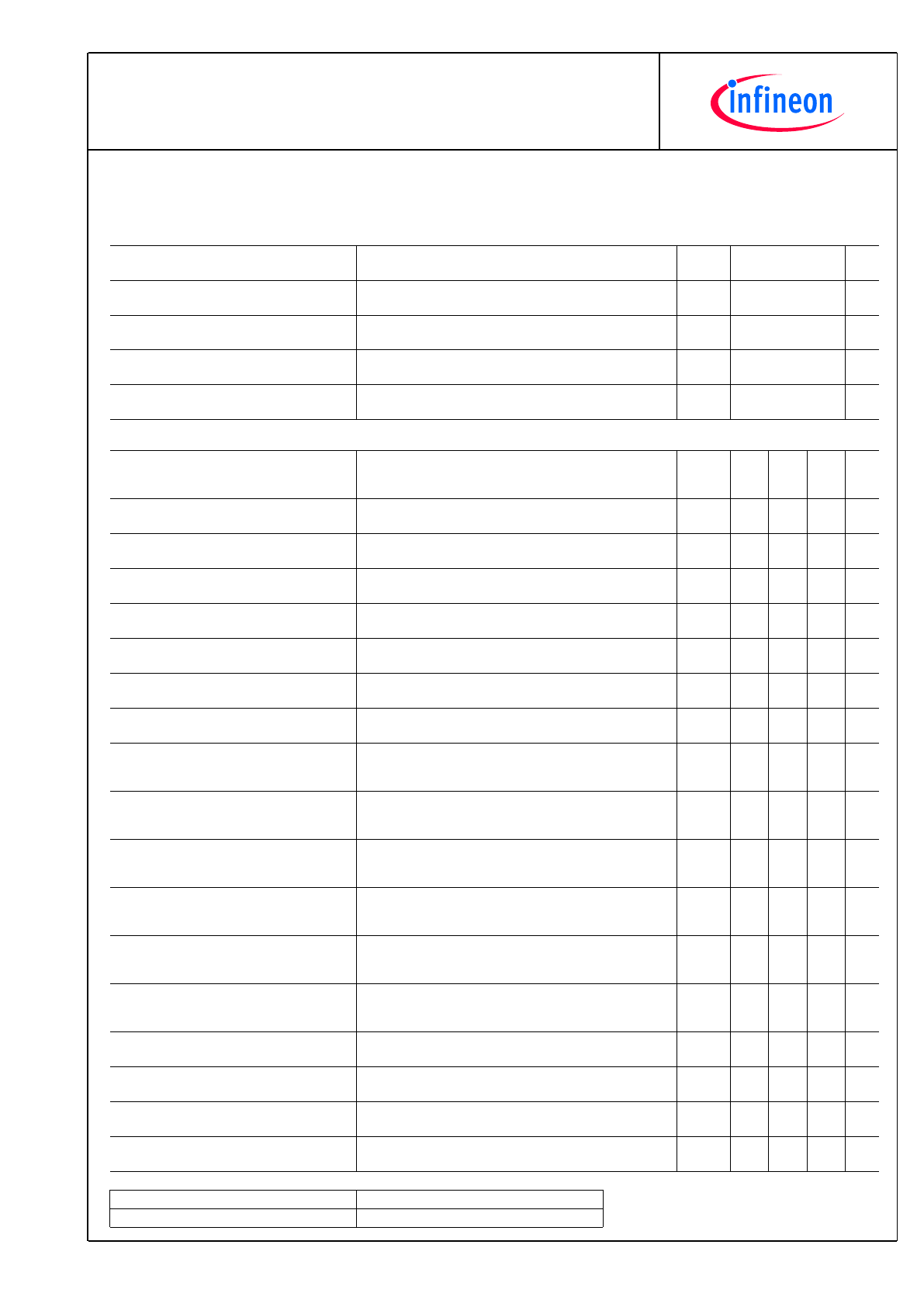
IGBT,Wechselrichter/IGBT,Inverter
HöchstzulässigeWerte/MaximumRatedValues
Kollektor-Emitter-Sperrspannung
Collector-emittervoltage
T
vj
= 25°C
V
CES
1700
V
Kollektor-Dauergleichstrom
ContinuousDCcollectorcurrent
T
C
= 100°C, T
vj max
= 175°C
T
C
= 25°C, T
vj max
= 175°C
I
C nom
I
C
1000
1390
A
A
PeriodischerKollektor-Spitzenstrom
Repetitivepeakcollectorcurrent
t
P
= 1 ms
I
CRM
2000
A
Gesamt-Verlustleistung
Totalpowerdissipation
T
C
= 25°C, T
vj max
= 175°C
P
tot
6,25
kW
Gate-Emitter-Spitzenspannung
Gate-emitterpeakvoltage
V
GES
+/-20
V
CharakteristischeWerte/CharacteristicValues
min.
typ.
max.
Kollektor-Emitter-Sättigungsspannung
Collector-emittersaturationvoltage
I
C
= 1000 A, V
GE
= 15 V
I
C
= 1000 A, V
GE
= 15 V
I
C
= 1000 A, V
GE
= 15 V
V
CE sat
2,00
2,35
2,45
2,45
2,80
V
V
V
T
vj
= 25°C
T
vj
= 125°C
T
vj
= 150°C
Gate-Schwellenspannung
Gatethresholdvoltage
I
C
= 36,0 mA, V
CE
= V
GE
, T
vj
= 25°C
V
GEth
5,2
5,8
6,4
V
Gateladung
Gatecharge
V
GE
= -15 V ... +15 V
Q
G
10,0
µC
InternerGatewiderstand
Internalgateresistor
T
vj
= 25°C
R
Gint
1,8
Ω
Eingangskapazität
Inputcapacitance
f = 1 MHz, T
vj
= 25°C, V
CE
= 25 V, V
GE
= 0 V
C
ies
81,0
nF
Rückwirkungskapazität
Reversetransfercapacitance
f = 1 MHz, T
vj
= 25°C, V
CE
= 25 V, V
GE
= 0 V
C
res
2,60
nF
Kollektor-Emitter-Reststrom
Collector-emittercut-offcurrent
V
CE
= 1700 V, V
GE
= 0 V, T
vj
= 25°C
I
CES
5,0
mA
Gate-Emitter-Reststrom
Gate-emitterleakagecurrent
V
CE
= 0 V, V
GE
= 20 V, T
vj
= 25°C
I
GES
400
nA
Einschaltverzögerungszeit,induktiveLast
Turn-ondelaytime,inductiveload
I
C
= 1000 A, V
CE
= 900 V
V
GE
= ±15 V
R
Gon
= 0,3
Ω
t
d on
0,66
0,70
0,71
µs
µs
µs
T
vj
= 25°C
T
vj
= 125°C
T
vj
= 150°C
Anstiegszeit,induktiveLast
Risetime,inductiveload
I
C
= 1000 A, V
CE
= 900 V
V
GE
= ±15 V
R
Gon
= 0,3
Ω
t
r
0,10
0,11
0,12
µs
µs
µs
T
vj
= 25°C
T
vj
= 125°C
T
vj
= 150°C
Abschaltverzögerungszeit,induktiveLast
Turn-offdelaytime,inductiveload
I
C
= 1000 A, V
CE
= 900 V
V
GE
= ±15 V
R
Goff
= 1,2
Ω
t
d off
1,15
1,30
1,35
µs
µs
µs
T
vj
= 25°C
T
vj
= 125°C
T
vj
= 150°C
Fallzeit,induktiveLast
Falltime,inductiveload
I
C
= 1000 A, V
CE
= 900 V
V
GE
= ±15 V
R
Goff
= 1,2
Ω
t
f
0,25
0,48
0,56
µs
µs
µs
T
vj
= 25°C
T
vj
= 125°C
T
vj
= 150°C
EinschaltverlustenergieproPuls
Turn-onenergylossperpulse
I
C
= 1000 A, V
CE
= 900 V, L
S
= 30 nH
V
GE
= ±15 V, di/dt = 8900 A/µs (T
vj
= 150°C)
R
Gon
= 0,3
Ω
E
on
260
365
415
mJ
mJ
mJ
T
vj
= 25°C
T
vj
= 125°C
T
vj
= 150°C
AbschaltverlustenergieproPuls
Turn-offenergylossperpulse
I
C
= 1000 A, V
CE
= 900 V, L
S
= 30 nH
V
GE
= ±15 V, du/dt = 2800 V/µs (T
vj
= 150°C)
R
Goff
= 1,2
Ω
E
off
210
315
345
mJ
mJ
mJ
T
vj
= 25°C
T
vj
= 125°C
T
vj
= 150°C
Kurzschlußverhalten
SCdata
V
GE
≤
15 V, V
CC
= 1000 V
V
CEmax
= V
CES
-L
sCE
·di/dt
I
SC
4000
A
T
vj
= 150°C
t
P
≤
10 µs,
Wärmewiderstand,ChipbisGehäuse
Thermalresistance,junctiontocase
proIGBT/perIGBT
R
thJC
24,0 K/kW
Wärmewiderstand,GehäusebisKühlkörper
Thermalresistance,casetoheatsink
proIGBT/perIGBT
λ
Paste
=1W/(m·K)/
λ
grease
=1W/(m·K)
R
thCH
10,0
K/kW
TemperaturimSchaltbetrieb
Temperatureunderswitchingconditions
T
vj op
-40
150
°C
3
TechnischeInformation/TechnicalInformation
FF1000R17IE4D_B2
IGBT-Module
IGBT-modules
preparedby:TA
approvedby:PL
dateofpublication:2013-11-05
revision:2.1
VorläufigeDaten
PreliminaryData
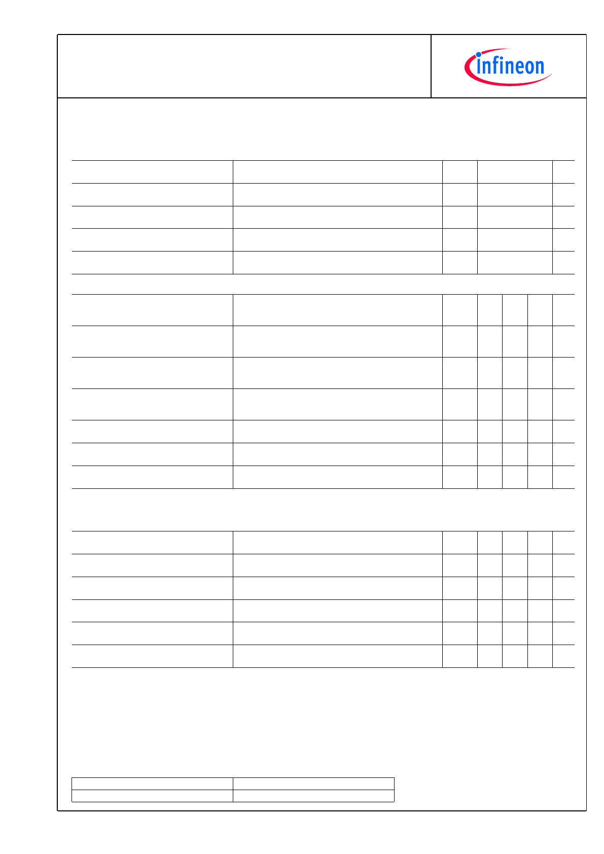
Diode,Wechselrichter/Diode,Inverter
HöchstzulässigeWerte/MaximumRatedValues
PeriodischeSpitzensperrspannung
Repetitivepeakreversevoltage
T
vj
= 25°C
V
RRM
1700
V
Dauergleichstrom
ContinuousDCforwardcurrent
I
F
1000
A
PeriodischerSpitzenstrom
Repetitivepeakforwardcurrent
t
P
= 1 ms
I
FRM
2000
A
Grenzlastintegral
I²t-value
V
R
= 0 V, t
P
= 10 ms, T
vj
= 125°C
V
R
= 0 V, t
P
= 10 ms, T
vj
= 150°C
I²t
185
175
kA²s
kA²s
Spitzenverlustleistung
Maximumpowerdissipation
T
vj
= 125°C
P
RQM
1250
kW
CharakteristischeWerte/CharacteristicValues
min.
typ.
max.
Durchlassspannung
Forwardvoltage
I
F
= 1000 A, V
GE
= 0 V
I
F
= 1000 A, V
GE
= 0 V
I
F
= 1000 A, V
GE
= 0 V
V
F
1,70
1,70
1,70
2,15
V
V
V
T
vj
= 25°C
T
vj
= 125°C
T
vj
= 150°C
Rückstromspitze
Peakreverserecoverycurrent
I
F
= 1000 A, - di
F
/dt = 8900 A/µs (T
vj
=150°C)
V
R
= 900 V
V
GE
= -15 V
I
RM
1300
1400
1450
A
A
A
T
vj
= 25°C
T
vj
= 125°C
T
vj
= 150°C
Sperrverzögerungsladung
Recoveredcharge
I
F
= 1000 A, - di
F
/dt = 8900 A/µs (T
vj
=150°C)
V
R
= 900 V
V
GE
= -15 V
Q
r
285
460
520
µC
µC
µC
T
vj
= 25°C
T
vj
= 125°C
T
vj
= 150°C
AbschaltenergieproPuls
Reverserecoveryenergy
I
F
= 1000 A, - di
F
/dt = 8900 A/µs (T
vj
=150°C)
V
R
= 900 V
V
GE
= -15 V
E
rec
145
260
295
mJ
mJ
mJ
T
vj
= 25°C
T
vj
= 125°C
T
vj
= 150°C
Wärmewiderstand,ChipbisGehäuse
Thermalresistance,junctiontocase
proDiode/perdiode
R
thJC
35,0 K/kW
Wärmewiderstand,GehäusebisKühlkörper
Thermalresistance,casetoheatsink
proDiode/perdiode
λ
Paste
=1W/(m·K)/
λ
grease
=1W/(m·K)
R
thCH
15,0
K/kW
TemperaturimSchaltbetrieb
Temperatureunderswitchingconditions
T
vj op
-40
150
°C
NTC-Widerstand/NTC-Thermistor
CharakteristischeWerte/CharacteristicValues
min.
typ.
max.
Nennwiderstand
Ratedresistance
T
C
= 25°C
R
25
5,00
k
Ω
AbweichungvonR100
DeviationofR100
T
C
= 100°C, R
100
= 493
Ω
∆
R/R
-5
5
%
Verlustleistung
Powerdissipation
T
C
= 25°C
P
25
20,0
mW
B-Wert
B-value
R
2
= R
25
exp [B
25/50
(1/T
2
- 1/(298,15 K))]
B
25/50
3375
K
B-Wert
B-value
R
2
= R
25
exp [B
25/80
(1/T
2
- 1/(298,15 K))]
B
25/80
3411
K
B-Wert
B-value
R
2
= R
25
exp [B
25/100
(1/T
2
- 1/(298,15 K))]
B
25/100
3433
K
AngabengemäßgültigerApplicationNote.
Specificationaccordingtothevalidapplicationnote.
4
TechnischeInformation/TechnicalInformation
FF1000R17IE4D_B2
IGBT-Module
IGBT-modules
preparedby:TA
approvedby:PL
dateofpublication:2013-11-05
revision:2.1
VorläufigeDaten
PreliminaryData
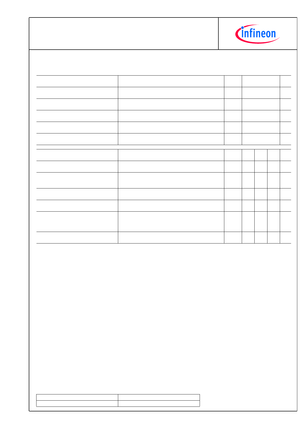
Modul/Module
Isolations-Prüfspannung
Isolationtestvoltage
RMS, f = 50 Hz, t = 1 min.
V
ISOL
4,0
kV
MaterialModulgrundplatte
Materialofmodulebaseplate
Cu
InnereIsolation
Internalisolation
Basisisolierung(Schutzklasse1,EN61140)
basicinsulation(class1,IEC61140)
Al
2
O
3
Kriechstrecke
Creepagedistance
Kontakt-Kühlkörper/terminaltoheatsink
Kontakt-Kontakt/terminaltoterminal
33,0
33,0
mm
Luftstrecke
Clearance
Kontakt-Kühlkörper/terminaltoheatsink
Kontakt-Kontakt/terminaltoterminal
19,0
19,0
mm
VergleichszahlderKriechwegbildung
Comperativetrackingindex
CTI
> 400
min.
typ.
max.
Wärmewiderstand,GehäusebisKühlkörper
Thermalresistance,casetoheatsink
proModul/permodule
λ
Paste
=1W/(m·K)/
λ
grease
=1W/(m·K)
R
thCH
3,00
K/kW
Modulstreuinduktivität
Strayinductancemodule
L
sCE
10
nH
Modulleitungswiderstand,Anschlüsse-
Chip
Moduleleadresistance,terminals-chip
T
C
=25°C,proSchalter/perswitch
R
CC'+EE'
0,20
m
Ω
Lagertemperatur
Storagetemperature
T
stg
-40
150
°C
Anzugsdrehmomentf.Modulmontage
Mountingtorqueformodulmounting
SchraubeM5-Montagegem.gültigerApplikationsschrift
ScrewM5-Mountingaccordingtovalidapplicationnote
M
3,00
-
6,00
Nm
Anzugsdrehmomentf.elektr.Anschlüsse
Terminalconnectiontorque
SchraubeM4-Montagegem.gültigerApplikationsschrift
ScrewM4-Mountingaccordingtovalidapplicationnote
SchraubeM8-Montagegem.gültigerApplikationsschrift
ScrewM8-Mountingaccordingtovalidapplicationnote
M
1,8
8,0
-
-
2,1
10
Nm
Nm
Gewicht
Weight
G
1200
g
5
TechnischeInformation/TechnicalInformation
FF1000R17IE4D_B2
IGBT-Module
IGBT-modules
preparedby:TA
approvedby:PL
dateofpublication:2013-11-05
revision:2.1
VorläufigeDaten
PreliminaryData
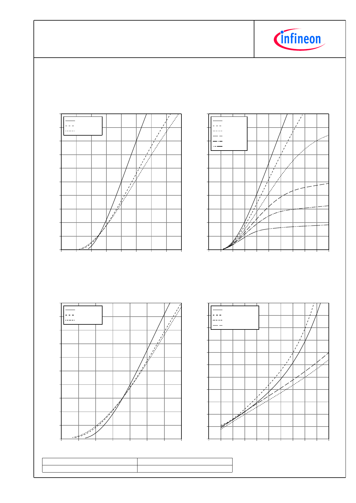
AusgangskennlinieIGBT,Wechselrichter(typisch)
outputcharacteristicIGBT,Inverter(typical)
I
C
=f(V
CE
)
V
GE
=15V
V
CE
[V]
I
C
[A]
0,0
0,5
1,0
1,5
2,0
2,5
3,0
3,5
4,0
0
200
400
600
800
1000
1200
1400
1600
1800
2000
T
vj
= 25°C
T
vj
= 125°C
T
vj
= 150°C
AusgangskennlinienfeldIGBT,Wechselrichter(typisch)
outputcharacteristicIGBT,Inverter(typical)
I
C
=f(V
CE
)
T
vj
=150°C
V
CE
[V]
I
C
[A]
0,0
0,5
1,0
1,5
2,0
2,5
3,0
3,5
4,0
4,5
5,0
0
200
400
600
800
1000
1200
1400
1600
1800
2000
V
GE
= 20V
V
GE
= 15V
V
GE
= 12V
V
GE
= 10V
V
GE
= 9V
V
GE
= 8V
ÜbertragungscharakteristikIGBT,Wechselrichter(typisch)
transfercharacteristicIGBT,Inverter(typical)
I
C
=f(V
GE
)
V
CE
=20V
V
GE
[V]
I
C
[A]
5
6
7
8
9
10
11
12
0
200
400
600
800
1000
1200
1400
1600
1800
2000
T
vj
= 25°C
T
vj
= 125°C
T
vj
= 150°C
SchaltverlusteIGBT,Wechselrichter(typisch)
switchinglossesIGBT,Inverter(typical)
E
on
=f(I
C
),E
off
=f(I
C
)
V
GE
=±15V,R
Gon
=0.3
Ω
,R
Goff
=1.2
Ω
,V
CE
=900V
I
C
[A]
E [mJ]
0
200 400 600 800 1000 1200 1400 1600 1800 2000
0
100
200
300
400
500
600
700
800
900
1000
1100
E
on
, T
vj
= 125°C
E
on
, T
vj
= 150°C
E
off
, T
vj
= 125°C
E
off
, T
vj
= 150°C
6
TechnischeInformation/TechnicalInformation
FF1000R17IE4D_B2
IGBT-Module
IGBT-modules
preparedby:TA
approvedby:PL
dateofpublication:2013-11-05
revision:2.1
VorläufigeDaten
PreliminaryData
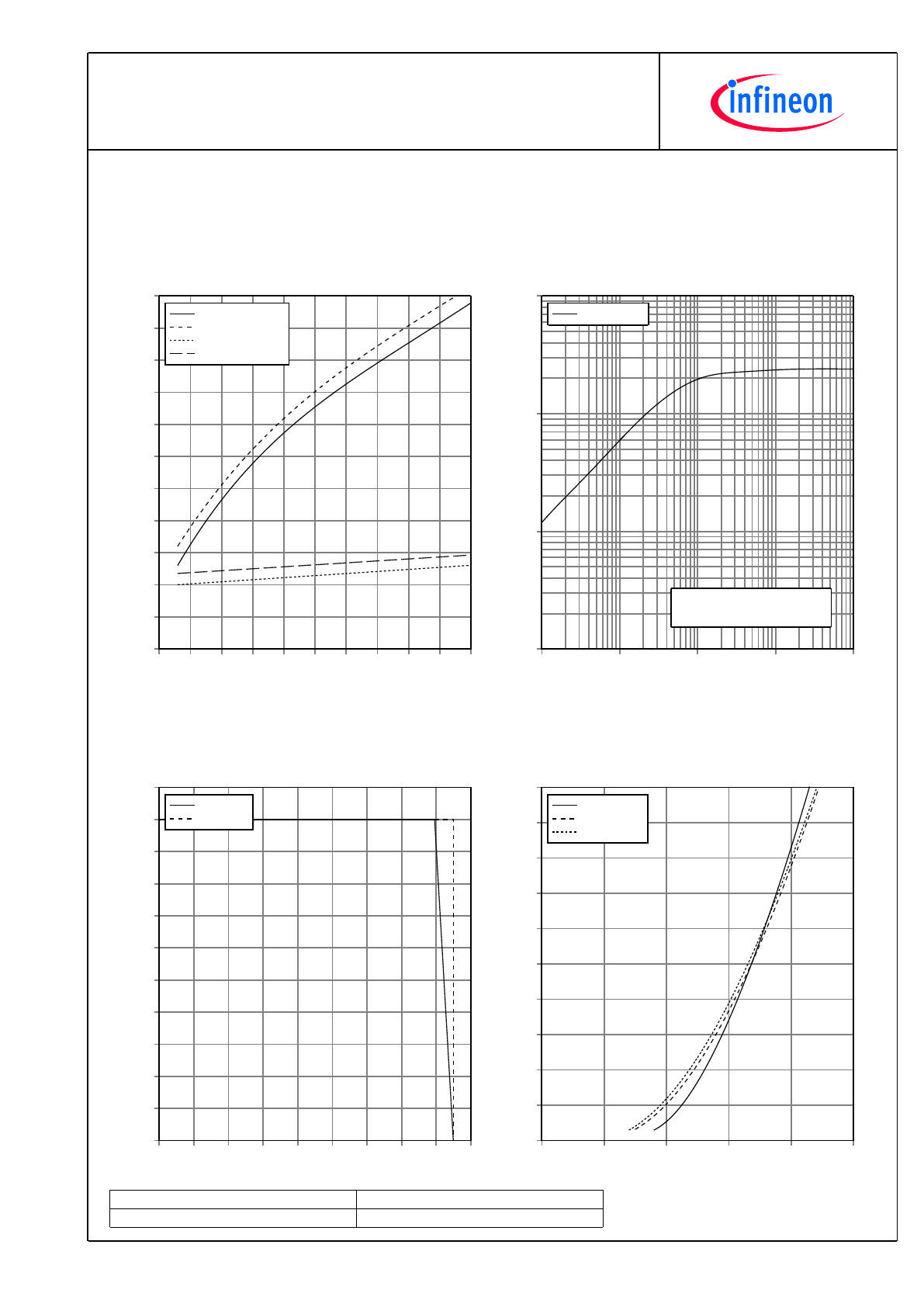
SchaltverlusteIGBT,Wechselrichter(typisch)
switchinglossesIGBT,Inverter(typical)
E
on
=f(R
G
),E
off
=f(R
G
)
V
GE
=±15V,I
C
=1000A,V
CE
=900V
R
G
[
Ω
]
E [mJ]
0,0
0,5
1,0
1,5
2,0
2,5
3,0
3,5
4,0
4,5
5,0
100
200
300
400
500
600
700
800
900
1000
1100
1200
E
on
, T
vj
= 125°C
E
on
, T
vj
= 150°C
E
off
, T
vj
= 125°C
E
off
, T
vj
= 150°C
TransienterWärmewiderstandIGBT,Wechselrichter
transientthermalimpedanceIGBT,Inverter
Z
thJC
=f(t)
t [s]
Z
thJC
[K/kW]
0,001
0,01
0,1
1
10
0,1
1
10
100
Z
thJC
: IGBT
i:
r
i
[K/kW]:
τ
i
[s]:
1
0,8
0,0008
2
3,7
0,013
3
17
0,05
4
2,5
0,6
SichererRückwärts-ArbeitsbereichIGBT,Wechselrichter
(RBSOA)
reversebiassafeoperatingareaIGBT,Inverter(RBSOA)
I
C
=f(V
CE
)
V
GE
=±15V,R
Goff
=1.2
Ω
,T
vj
=150°C
V
CE
[V]
I
C
[A]
0
200
400
600
800 1000 1200 1400 1600 1800
0
200
400
600
800
1000
1200
1400
1600
1800
2000
2200
I
C
, Modul
I
C
, Chip
DurchlasskennliniederDiode,Wechselrichter(typisch)
forwardcharacteristicofDiode,Inverter(typical)
I
F
=f(V
F
)
V
F
[V]
I
F
[A]
0,0
0,5
1,0
1,5
2,0
2,5
0
200
400
600
800
1000
1200
1400
1600
1800
2000
T
vj
= 25°C
T
vj
= 125°C
T
vj
= 150°C
7
TechnischeInformation/TechnicalInformation
FF1000R17IE4D_B2
IGBT-Module
IGBT-modules
preparedby:TA
approvedby:PL
dateofpublication:2013-11-05
revision:2.1
VorläufigeDaten
PreliminaryData
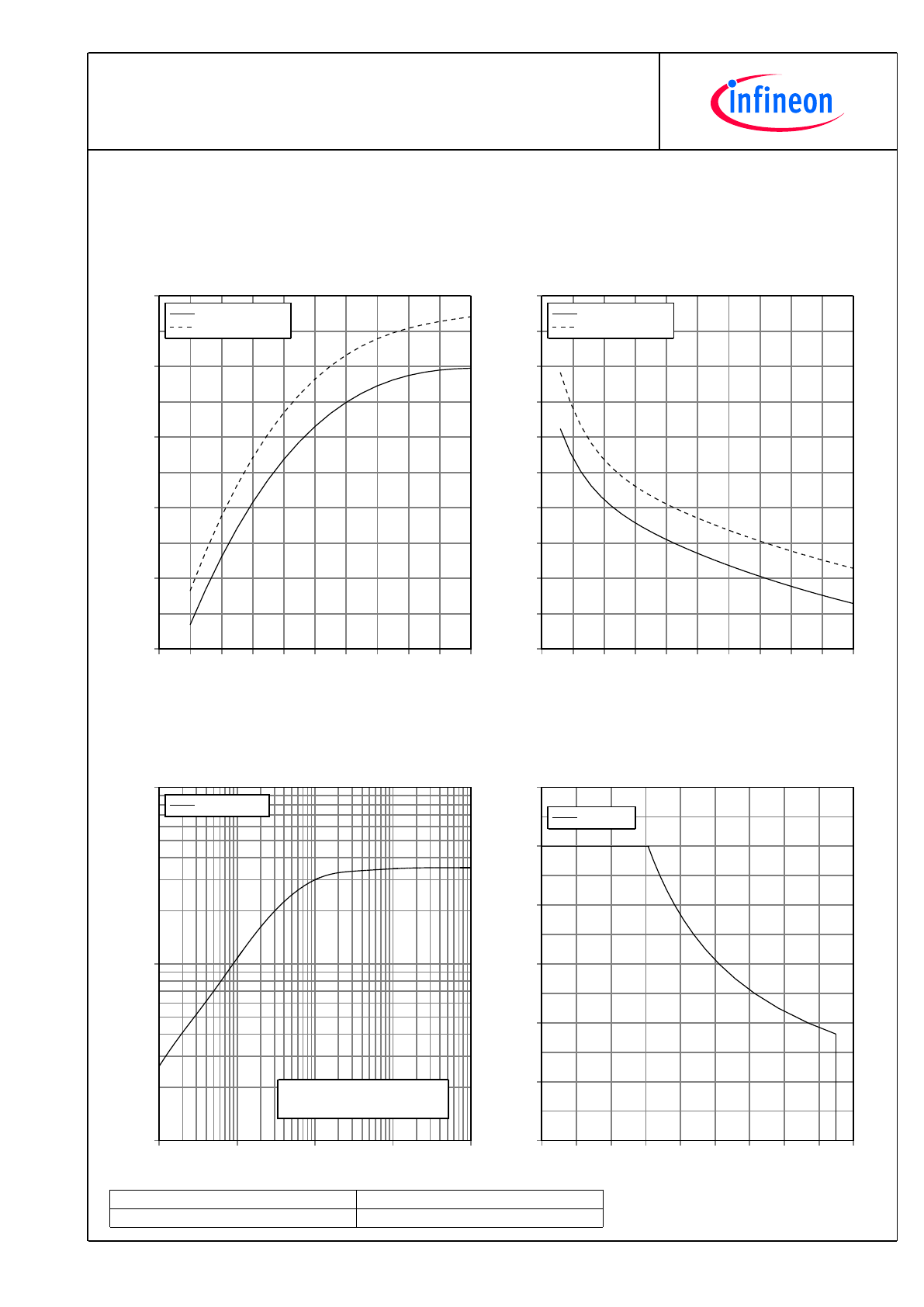
SchaltverlusteDiode,Wechselrichter(typisch)
switchinglossesDiode,Inverter(typical)
E
rec
=f(I
F
)
R
Gon
=0.3
Ω
,V
CE
=900V
I
F
[A]
E [mJ]
0
200 400 600 800 1000 1200 1400 1600 1800 2000
100
150
200
250
300
350
E
rec
, T
vj
= 125°C
E
rec
, T
vj
= 150°C
SchaltverlusteDiode,Wechselrichter(typisch)
switchinglossesDiode,Inverter(typical)
E
rec
=f(R
G
)
I
F
=1000A,V
CE
=900V
R
G
[
Ω
]
E [mJ]
0,0
0,5
1,0
1,5
2,0
2,5
3,0
3,5
4,0
4,5
5,0
100
125
150
175
200
225
250
275
300
325
350
E
rec
, T
vj
= 125°C
E
rec
, T
vj
= 150°C
TransienterWärmewiderstandDiode,Wechselrichter
transientthermalimpedanceDiode,Inverter
Z
thJC
=f(t)
t [s]
Z
thJC
[K/kW]
0,001
0,01
0,1
1
10
1
10
100
Z
thJC
: Diode
i:
r
i
[K/kW]:
τ
i
[s]:
1
2,19
0,0008
2
8,41
0,013
3
21,94
0,05
4
2,56
0,6
SichererArbeitsbereichDiode,Wechselrichter(SOA)
safeoperationareaDiode,Inverter(SOA)
I
R
=f(V
R
)
T
vj
=150°C
V
R
[V]
I
R
[A]
0
200
400
600
800 1000 1200 1400 1600 1800
0
400
800
1200
1600
2000
2400
I
R
, Modul
8
TechnischeInformation/TechnicalInformation
FF1000R17IE4D_B2
IGBT-Module
IGBT-modules
preparedby:TA
approvedby:PL
dateofpublication:2013-11-05
revision:2.1
VorläufigeDaten
PreliminaryData
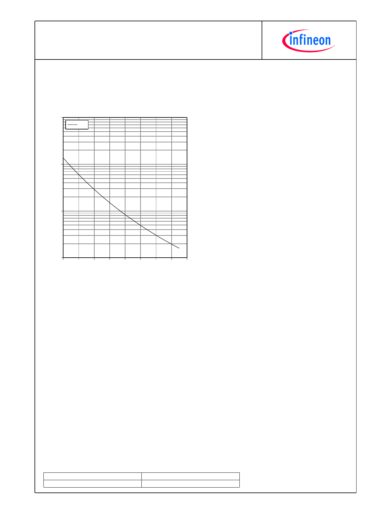
NTC-Widerstand-Temperaturkennlinie(typisch)
NTC-Thermistor-temperaturecharacteristic(typical)
R=f(T)
T
C
[°C]
R[
Ω
]
0
20
40
60
80
100
120
140
160
100
1000
10000
100000
R
typ
9
TechnischeInformation/TechnicalInformation
FF1000R17IE4D_B2
IGBT-Module
IGBT-modules
preparedby:TA
approvedby:PL
dateofpublication:2013-11-05
revision:2.1
VorläufigeDaten
PreliminaryData
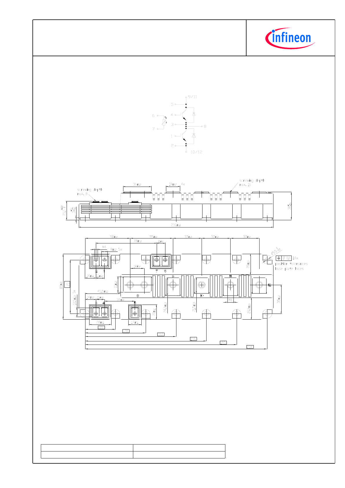
Schaltplan/circuit_diagram_headline
Gehäuseabmessungen/packageoutlines
10
TechnischeInformation/TechnicalInformation
FF1000R17IE4D_B2
IGBT-Module
IGBT-modules
preparedby:TA
approvedby:PL
dateofpublication:2013-11-05
revision:2.1
VorläufigeDaten
PreliminaryData
Nutzungsbedingungen
DieindiesemProduktdatenblattenthaltenenDatensindausschließlichfürtechnischgeschultesFachpersonalbestimmt.DieBeurteilung
derEignungdiesesProduktesfürIhreAnwendungsowiedieBeurteilungderVollständigkeitderbereitgestelltenProduktdatenfürdiese
AnwendungobliegtIhnenbzw.IhrentechnischenAbteilungen.
IndiesemProduktdatenblattwerdendiejenigenMerkmalebeschrieben,fürdiewireineliefervertraglicheGewährleistungübernehmen.Eine
solcheGewährleistungrichtetsichausschließlichnachMaßgabederimjeweiligenLiefervertragenthaltenenBestimmungen.Garantien
jeglicherArtwerdenfürdasProduktunddessenEigenschaftenkeinesfallsübernommen.DieAngabenindengültigenAnwendungs-und
MontagehinweisendesModulssindzubeachten.
SolltenSievonunsProduktinformationenbenötigen,dieüberdenInhaltdiesesProduktdatenblattshinausgehenundinsbesondereeine
spezifischeVerwendungunddenEinsatzdiesesProduktesbetreffen,setzenSiesichbittemitdemfürSiezuständigenVertriebsbüroin
Verbindung(siehewww.infineon.com,Vertrieb&Kontakt).FürInteressentenhaltenwirApplicationNotesbereit.
AufgrunddertechnischenAnforderungenkönnteunserProduktgesundheitsgefährdendeSubstanzenenthalten.BeiRückfragenzudenin
diesemProduktjeweilsenthaltenenSubstanzensetzenSiesichbitteebenfallsmitdemfürSiezuständigenVertriebsbüroinVerbindung.
SolltenSiebeabsichtigen,dasProduktinAnwendungenderLuftfahrt,ingesundheits-oderlebensgefährdendenoderlebenserhaltenden
Anwendungsbereicheneinzusetzen,bittenwirumMitteilung.Wirweisendaraufhin,dasswirfürdieseFälle
-diegemeinsameDurchführungeinesRisiko-undQualitätsassessments;
-denAbschlussvonspeziellenQualitätssicherungsvereinbarungen;
-diegemeinsameEinführungvonMaßnahmenzueinerlaufendenProduktbeobachtungdringendempfehlenund
gegebenenfallsdieBelieferungvonderUmsetzungsolcherMaßnahmenabhängigmachen.
Soweiterforderlich,bittenwirSie,entsprechendeHinweiseanIhreKundenzugeben.
InhaltlicheÄnderungendiesesProduktdatenblattsbleibenvorbehalten.
Terms&Conditionsofusage
Thedatacontainedinthisproductdatasheetisexclusivelyintendedfortechnicallytrainedstaff.Youandyourtechnicaldepartmentswill
havetoevaluatethesuitabilityoftheproductfortheintendedapplicationandthecompletenessoftheproductdatawithrespecttosuch
application.
Thisproductdatasheetisdescribingthecharacteristicsofthisproductforwhichawarrantyisgranted.Anysuchwarrantyisgranted
exclusivelypursuantthetermsandconditionsofthesupplyagreement.Therewillbenoguaranteeofanykindfortheproductandits
characteristics.Theinformationinthevalidapplication-andassemblynotesofthemodulemustbeconsidered.
Shouldyourequireproductinformationinexcessofthedatagiveninthisproductdatasheetorwhichconcernsthespecificapplicationof
ourproduct,pleasecontactthesalesoffice,whichisresponsibleforyou(seewww.infineon.com).Forthosethatarespecifically
interestedwemayprovideapplicationnotes.
Duetotechnicalrequirementsourproductmaycontaindangeroussubstances.Forinformationonthetypesinquestionpleasecontactthe
salesoffice,whichisresponsibleforyou.
ShouldyouintendtousetheProductinaviationapplications,inhealthorliveendangeringorlifesupportapplications,pleasenotify.Please
note,thatforanysuchapplicationsweurgentlyrecommend
-toperformjointRiskandQualityAssessments;
-theconclusionofQualityAgreements;
-toestablishjointmeasuresofanongoingproductsurvey,andthatwemaymakedeliverydependedon
therealizationofanysuchmeasures.
Ifandtotheextentnecessary,pleaseforwardequivalentnoticestoyourcustomers.
Changesofthisproductdatasheetarereserved.