
1
TechnicalInformation
6PS04512E43W39693
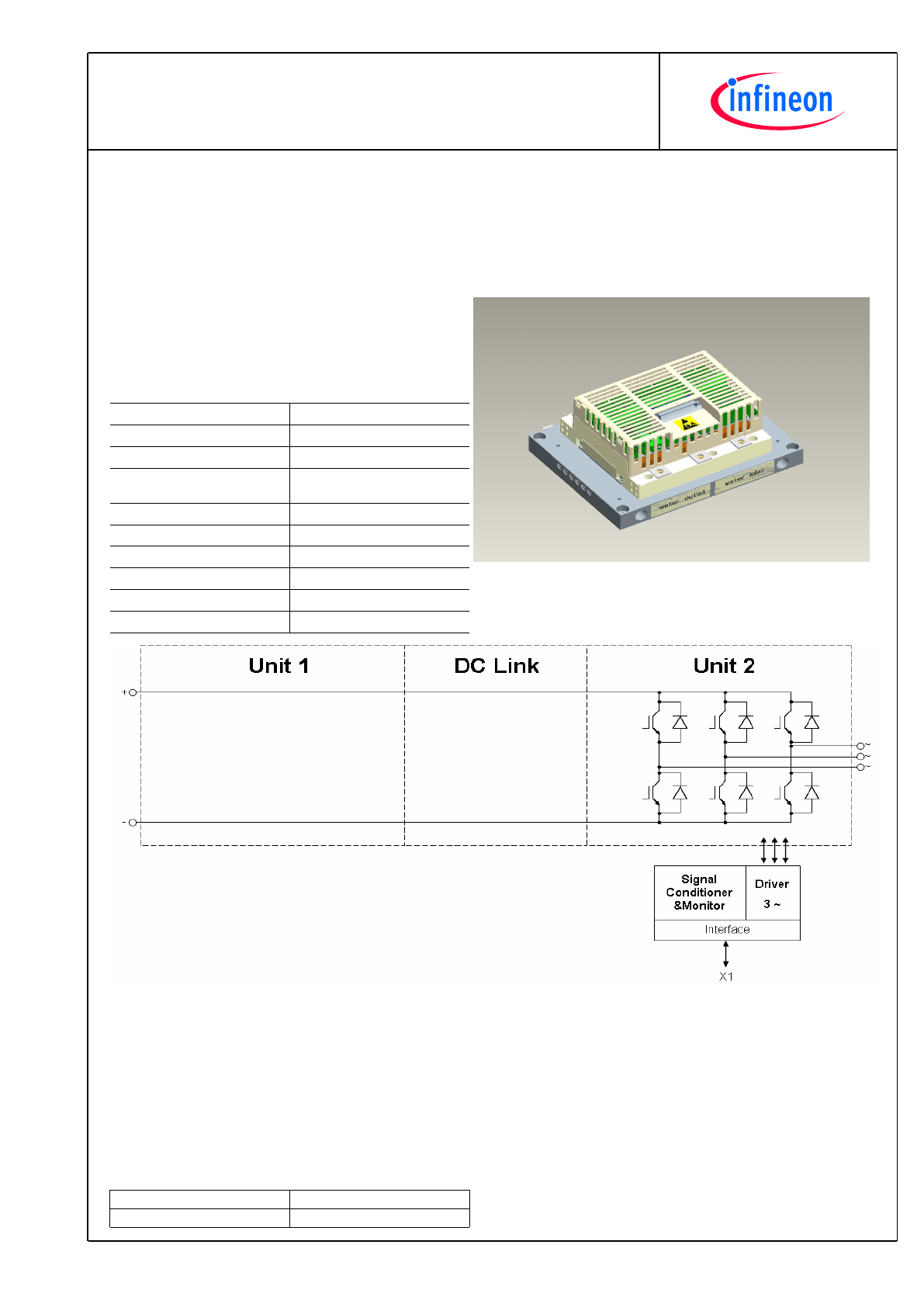
PrimeSTACK™
preparedby:OW
approvedby:AR
dateofpublication:2013-08-05
revision:2.0
Preliminarydata
Generalinformation
IGBTStackfortypicalvoltagesofupto500V
RMS
Ratedoutputcurrent300A
RMS
· High power converter
· Solar power
· Motor drives
· 62mm power module
Topology
B6I
Application
Inverter
Load type
Resistive, inductive
Semiconductor (Inverter
Section)
3x FF450R12KE4
Heatsink
Water cooled
Implemented sensors
Current, voltage, temperature
Driver signals IGBT
Electrical
Design standards
UL 94, prepared for UL 508C
Sales - name
6PS04512E43W39693
SP - No.
SP001129256
2
TechnicalInformation
6PS04512E43W39693
PrimeSTACK™
preparedby:OW
approvedby:AR
dateofpublication:2013-08-05
revision:2.0
Preliminarydata
Characteristicvalues
DCLink
min.
typ.
max.
Rated voltage
V
DC
650
V
Notes
The voltage sensor VM110 is only used for measurement.It is realized no over-voltage shutdown.
InverterSection
min.
typ.
max.
Rated continuous current
V
DC
= 800 V, V
AC
= 500 V
RMS
, cos(
ϕ
) = 0.85,
f
AC sine
= 5 Hz, f
sw
= 2500 Hz, T
inlet
= 40°C, T
j
≤
125 °C
I
AC
300
A
RMS
Continuous current at low
frequency
V
DC
= 800 V, V
AC
= 500 V
RMS
, f
AC sine
= 0 Hz,
f
sw
= 2500 Hz, T
inlet
= 40 °C, T
j
≤
125 °C
I
AC low
220
A
RMS
Rated continuous current for
150% overload capability
I
AC 150%
= 330 A
RMS
, t
on over
= 60 s, t
recovery
= 600 s,
T
j
≤
125 °C
I
AC over1
220
A
RMS
Over current shutdown
within 15 µs
I
AC OC
625
A
peak
Power losses
I
AC
= 500 A, V
DC
= 800 V, cos(
ϕ
) = 0.85, f
AC sine
= 5 Hz,
f
sw
= 2500 Hz, T
inlet
= 40 °C, T
j
≤
125 °C
P
loss
2400
W
Controllerinterface
Driver and interface board
ref. to separate Application Note
DR210
min.
typ.
max.
Auxiliary voltage
V
aux
18
24
30
V
Auxiliary power requirement
V
aux
= 24 V
P
aux
40
W
Digital input level
resistor to GND 10 k
Ω
, capacitor to GND 1 nF,
logic high = on
V
in low
0
1.5
V
V
in high
11
15
V
Digital output level
open collector, logic low = no fault, max. 15 mA
V
out low
0
1.5
V
V
out high
15
V
Analog current sensor output
inverter section
load max 5 mA, @ 300 A
RMS
V
IU ana2
V
IV ana2
V
IW ana2
4.7
4.9
5
V
Analog DC link voltage sensor
output
load max 5 mA, @ 900 V
V
DC ana
6.4
6.5
6.6
V
Analog temperature sensor
output unit 1 (NTC)
load max 5 mA,
corresponds to T
j
= 125 °C at rated conditions
V
Theta NTC1
4.9
V
Analog temperature sensor
output inverter section (NTC)
load max 5 mA, @T
NTC
= 82 °C
V
Theta NTC2
10
V
Notes
Over temperature shut down must be realized by customer.
3
TechnicalInformation
6PS04512E43W39693
PrimeSTACK™
preparedby:OW
approvedby:AR
dateofpublication:2013-08-05
revision:2.0
Preliminarydata
Systemdata
min.
typ.
max.
EMC robustness
according to IEC 61800-3 at named
interfaces
V
Burst
2
kV
power
V
Burst
1
kV
control
V
surge
1
kV
aux (24V)
Storage temperature
T
stor
-40
85
°C
Operational ambient
temperature
PCB, DC link capacitor, bus bar, excluding cooling
medium
T
op amb
-25
55
°C
Cooling air velocity
PCB, DC link capacitor, bus bar, standard atmosphere
V
air
0.3
m/s
Humidity
no condensation
Rel. F
5
85
%
Vibration
according to IEC60721
5
m/s²
Shock
according to IEC60721
40
m/s²
Protection degree
IP00
Pollution degree
2
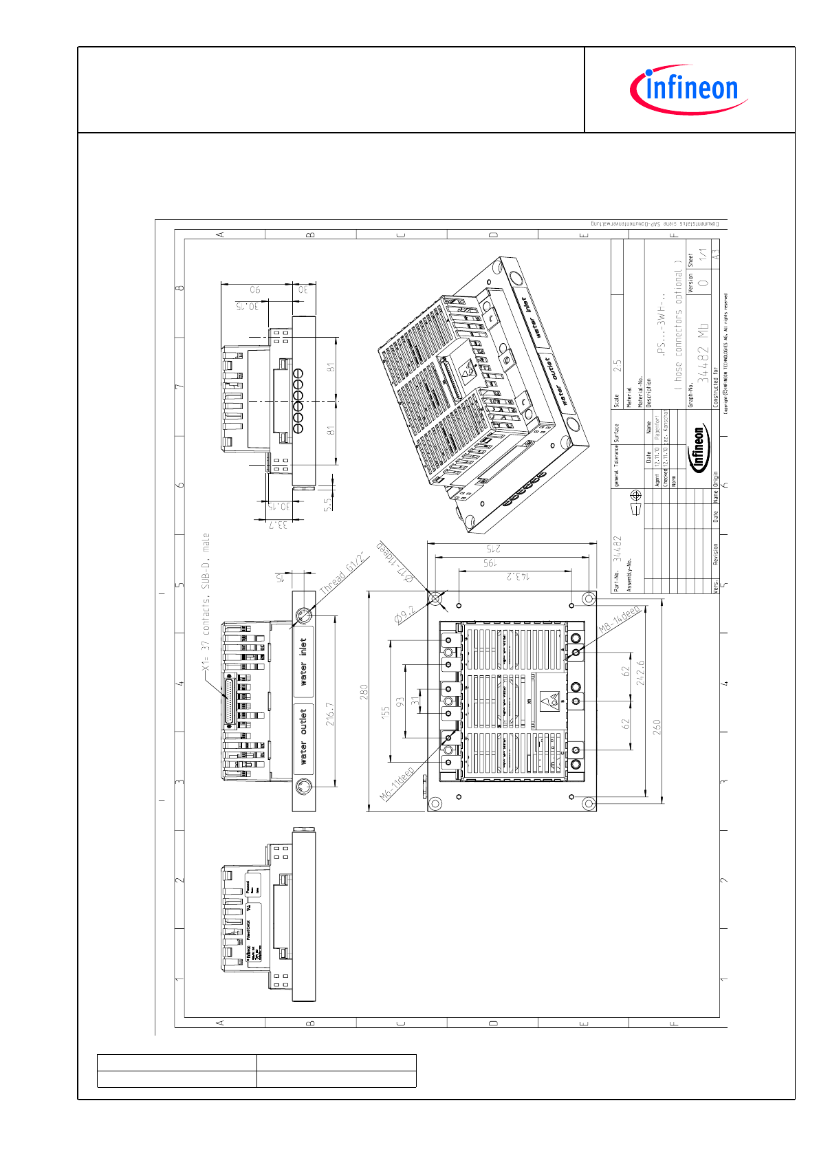
Dimensions
width x depth x height
215
280
120
mm
Weight
7.7
kg
Heatsinkwatercooled
min.
typ.
max.
Water flow
according to coolant specification from Infineon
∆
V/
∆
t
10
dm³/min
Water pressure
8
bar
Water pressure drop
∆
p
50
mbar
Coolant inlet temperature
T
inlet
-40
40
°C
Overviewofoptionalcomponents
Unit 1
Inverter
Section
Unit 3
Parallel interface board
Optical interface board
Voltage sensor
×
Current sensor
×
Temperature sensor
×
Temperature simulation
DC link capacitors
Collector-emitter Active Clamping
Notes
Setting of Active Clamping TVS-Diodes: V
Z
= 824 V
4
TechnicalInformation
6PS04512E43W39693
PrimeSTACK™
preparedby:OW
approvedby:AR
dateofpublication:2013-08-05
revision:2.0
Preliminarydata
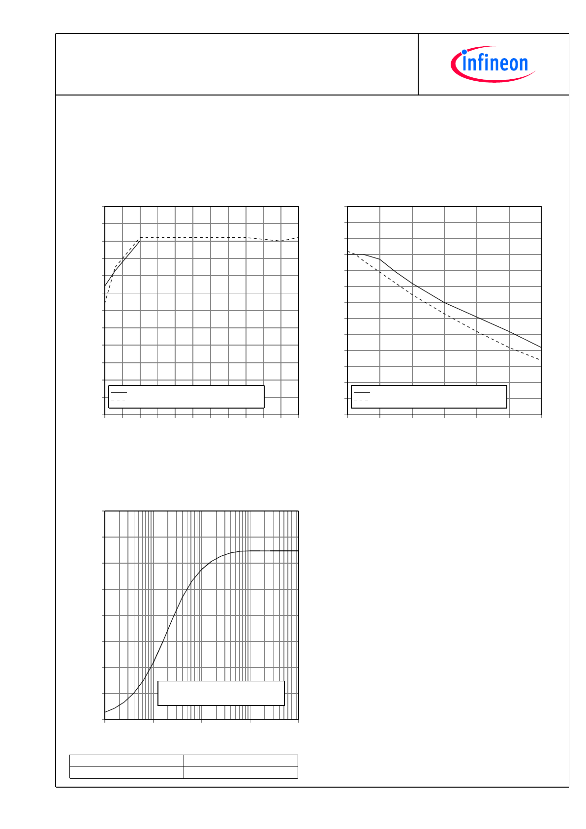
fo - derating curve IGBT (motor), Diode (generator)
cos(phi) = ±0,85
T
cool medium
= 40°C
f
0
[Hz]
I/I
norm
[%]
0
5
10
15
20
25
30
35
40
45
50
55
0
10
20
30
40
50
60
70
80
90
100
110
120
motor ; 100% = 300 A rms permanent
generator ; 100% = 295 A rms
fsw - derating curve IGBT (motor), Diode (generator)
cos(phi) = ±0,85
T
cool medium
= 40°C
f
sw
[Hz]
I/I
norm
[%]
2000
4000
6000
8000
10000
12000
14000
0
10
20
30
40
50
60
70
80
90
100
110
120
130
motor ; 100% = 300 A rms permanent
generator ; 100% = 295 A rms
Zth heat sink to ambient per switch
T
cool medium
= 40°C
time [s]
Zth heat sink to ambient [K/W]
0.1
1
10
100
1000
0.000
0.010
0.020
0.030
0.040
0.050
0.060
0.070
0.080
i:
r
i
[K/W]:
τ
i
[s]:
1
0.00002
0.966
2
0.03514
1.526
3
0.01938
4.172
4
0.0102
15.47
5
TechnicalInformation
6PS04512E43W39693
PrimeSTACK™
preparedby:OW
approvedby:AR
dateofpublication:2013-08-05
revision:2.0
Preliminarydata
Mechanicaldrawing
6
TechnicalInformation
6PS04512E43W39693
PrimeSTACK™
preparedby:OW
approvedby:AR
dateofpublication:2013-08-05
revision:2.0
Preliminarydata
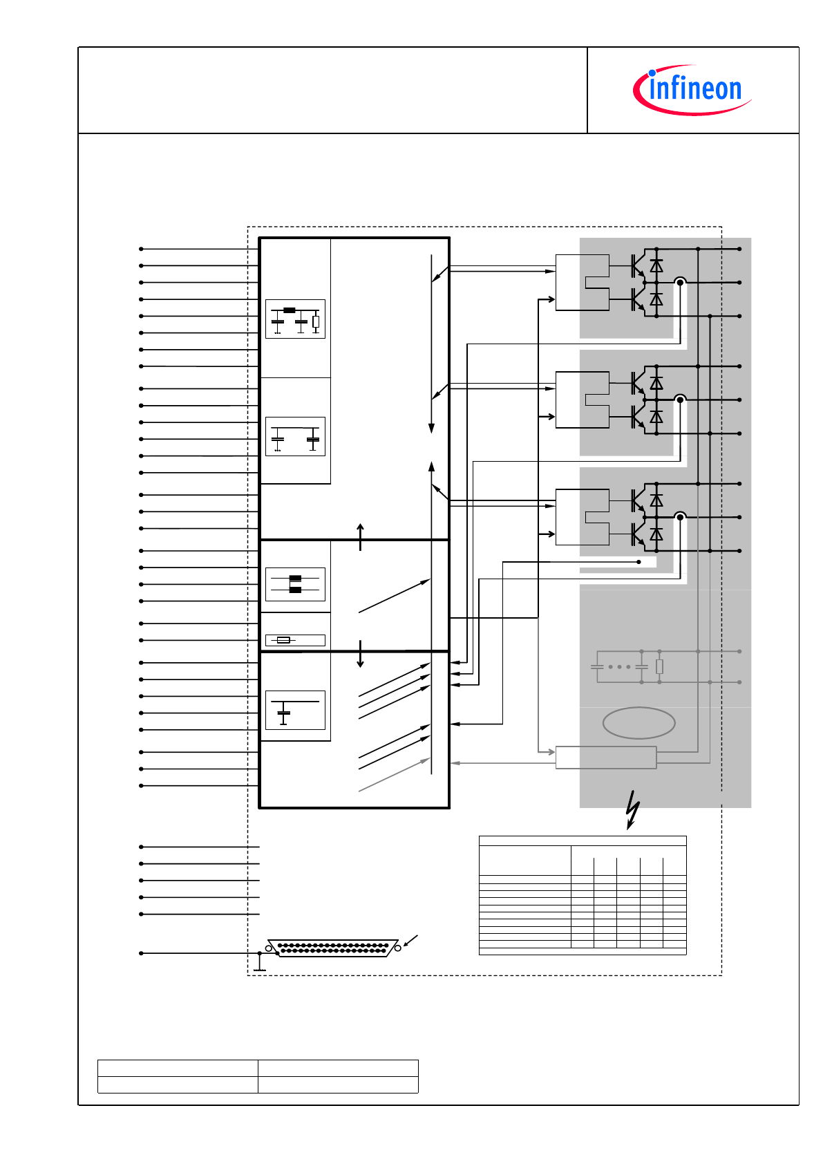
Circuitdiagram
+
-
B
Eic
eDRIV
ER
™
BOT
TOP
HB A IGBT BOT
Output
Input
20
21
3
4
HB B IGBT BOT
HB A IGBT TOP
HB B IGBT TOP
HB C IGBT BOT
HB C IGBT TOP
23
24
2 HB A error
HB B error
HB C error
22
5
6
16
15
Temp. error
Voltage error
NC
19
25
37
GND digital
GND digital
GND digital
Digita
l circuit
NC
NC
33
34
18
35
14
17
36
NC
NC
NC
NC
NC
1 True earth/shield
+
-
C
Eic
eDRIV
ER
™
BOT
TOP
J
+
-
A
Eic
eDRIV
ER
™
BOT
TOP
Anal
og
circ
uit
30
31
32
29
7
HB A current
HB B current
HB C current
Temperature
Voltage DC-Link
11
12
13
GND analog
GND analog
GND analog
Output
Power
sup
ply
10
28
8
26
13V÷30V
GND
GND
13V÷30V
In
Out
15V/50mA
15V/50mA
9
27
Overcurrent
HB A
Overcurrent
HB B
Overcurrent
HB C
Und
ervolta
ge
Overtemp
. output
stage
Overtemp
. PCB
Overvolta
ge
DC
-Link
Error
me
ssages
Error
me
ssages
Option V
Voltage measurement
High voltage
area in grey
V
CE(sat)
/ supply
V
CE(sat)
/ supply
V
CE(sat)
/ supply
PTC
X= high level with required external pull up resistor.
Error Table
X
Undervoltage power supply
X
X
X
X
Overvoltage DC-Link (Option)
X
Overtemperature PCB
X
X
X
X
Overtemperature output stage
X
X
X
Overcurrent HB C
X
X
X
Overcurrent HB B
X
X
X
Overcurrent HB A
X
Error Driver Core HB C
X
Error Driver Core HB B
X
Error Driver Core HB A
Voltage
Pin 16
Temp.
Pin 6
HB C
Pin 5
HB B
Pin 22
HB A
Pin 2
Error outputs (open collector)
Mana
For detailed technical information please refer the PrimeSTACK manual.
safety separation between
high voltage area and
low voltage area
6PS
-C3
-V
-Re
v03
SUB-D-Connector 37pole male
front view
1
female thread
UNC4/40
Option DC link capacitors
+
-
7
TechnicalInformation
6PS04512E43W39693
PrimeSTACK™
preparedby:OW
approvedby:AR
dateofpublication:2013-08-05
revision:2.0
Preliminarydata
Terms&Conditionsofusage
Thedatacontainedinthisproductdatasheetisexclusivelyintendedfortechnicallytrainedstaff.Youandyourtechnical
departmentswillhavetoevaluatethesuitabilityoftheproductfortheintendedapplicationandthecompletenessoftheproduct
datawithrespecttosuchapplication.
Thisproductdatasheetisdescribingthecharacteristicsofthisproductforwhichawarrantyisgranted.Anysuchwarrantyis
grantedexclusivelypursuantthetermsandconditionsofthesupplyagreement.Therewillbenoguaranteeofanykindforthe
productanditscharacteristics.
Shouldyourequireproductinformationinexcessofthedatagiveninthisproductdatasheetorwhichconcernsthespecific
applicationofourproduct,pleasecontactthesalesoffice,whichisresponsibleforyou(seewww.infineon.com,sales&contact).
Forthosethatarespecificallyinterestedwemayprovideapplicationnotes.
Duetotechnicalrequirementsourproductmaycontaindangeroussubstances.Forinformationonthetypesinquestionplease
contactthesalesoffice,whichisresponsibleforyou.
ShouldyouintendtousetheProductinaviationapplications,inhealthorliveendangeringorlifesupportapplications,please
notify.Pleasenote,thatforanysuchapplicationsweurgentlyrecommend
-toperformjointRiskandQualityAssessments;
-theconclusionofQualityAgreements;
-toestablishjointmeasuresofanongoingproductsurvey,
andthatwemaymakedeliverydependedontherealization
ofanysuchmeasures.
Ifandtotheextentnecessary,pleaseforwardequivalentnoticestoyourcustomers.
Changesofthisproductdatasheetarereserved.
SafetyInstructions
Priortoinstallationandoperation,allsafetynoticesandwarningsandallwarningsignsattachedtotheequipmenthavetobe
carefullyread.Makesurethatallwarningsignsremaininalegibleconditionandthatmissingordamagedsignsarereplaced.To
installationandoperation,allsafetynoticesandwarningsandallwarningsignsattachedtotheequipmenthavetobecarefully
read.Makesurethatallwarningsignsremaininalegibleconditionandthatmissingordamagedsignsarereplaced.