
1
TechnicalInformation
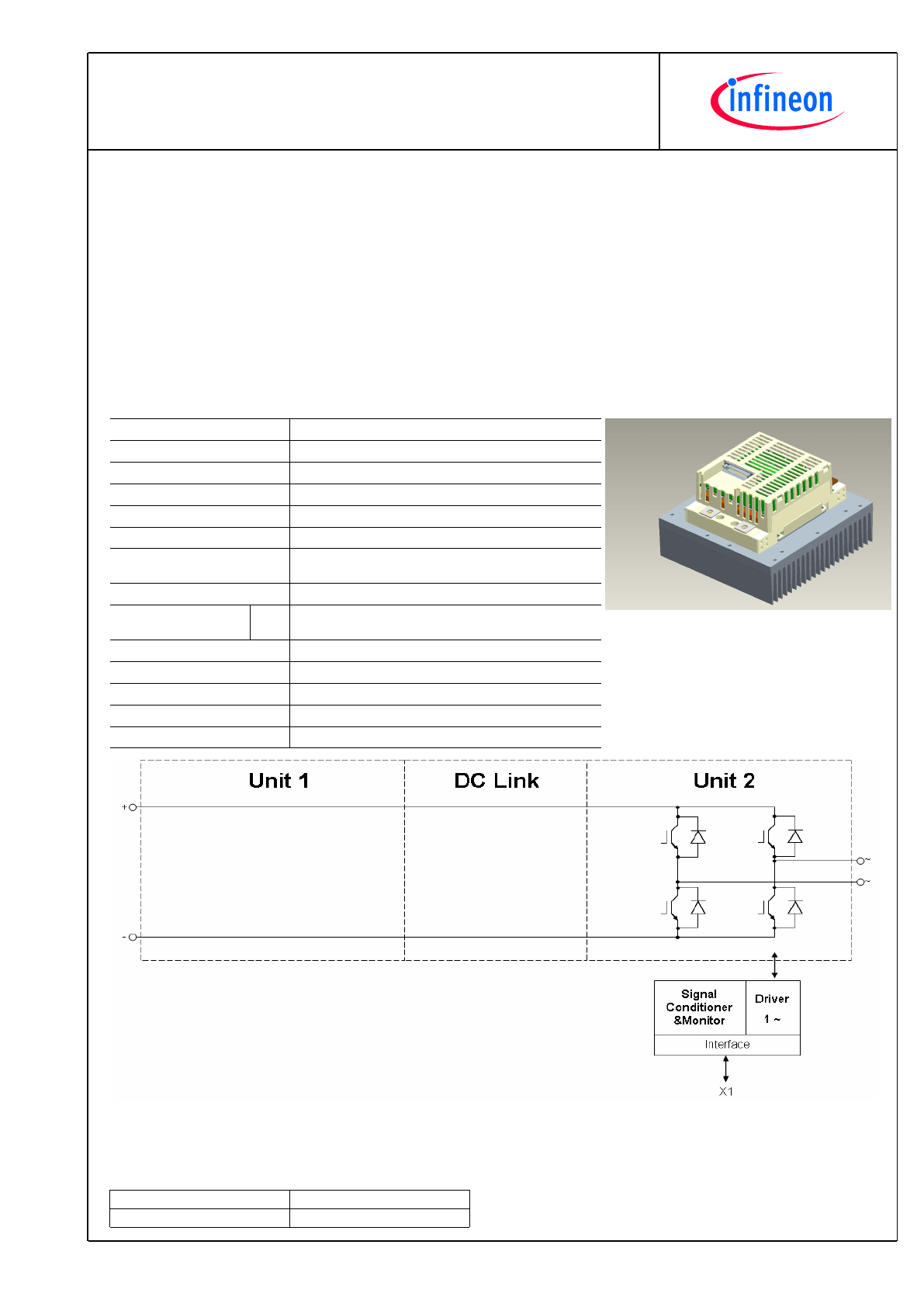
2PS06017E32G28213
PrimeSTACK™
preparedby:OW
approvedby:AR
dateofpublication:2013-05-03
revision:2.0
Preliminarydata
Keydata
1x325AACat690VAC,forcedair(fannotimplemented)
Generalinformation
Stacksforvariousinverterapplication.Semiconductors,heatsinks,driversandsensorsincluded.
Theseareonlytechnicaldata
Pleasereadcarefullythecompletedocumentationandmaintaintheproperdesignenvironment
EspeciallynotetheEMCenvironmentandthecontroller'sfunctionality.
Topology
1/2 B2I
Application / Modulation
Inverter / Sine
Load type
resistive, inductive
Cooling
forced air (fan not implemented)
Market
common industrial, drives, power supply
Implemented sensors
current, temperature
Semicond.
(Unit 1)
none
DC Link
none
Semicond.
(Unit 2)
2x FF300R17KE3
IGBT
Driver signals IGBT
electrical CMOS
Standards
EN50178, UL94, prepared for UL508C
Internal ID
28213
Mechanical drawing number
38000028
Electrical drawing number
2PS-C2-V
2
TechnicalInformation
2PS06017E32G28213
PrimeSTACK™
preparedby:OW
approvedby:AR
dateofpublication:2013-05-03
revision:2.0
Preliminarydata
Notes
Overvoltage shutdown:
It must be realized by the customer.
Overvoltage and Overcurrent shutdown reaction time:
This parameter refers to the customers controller.
Electricaldata
DCLink
min
typ
max
units
Voltage
V
DC
1100
1200
V
Unit2AC
min
typ
max
units
Voltage
V
Unit2
690
V
RMS
Continuous current
V
Unit2
= 690V
RMS
, V
DC
= 1100V, T
inlet
= 40°C,
T
J
≤
125°C, f
Unit2
= 50Hz, f
sw2
= 2000Hz,
cos(phi) = 0,85
I
Unit2
325
A
RMS
Continuous current overload
cap.
T
inlet
= 40°C, for overload capability 150% for 60s
231
A
RMS
Short time current
T
inlet
= 40°C, 10s, every 180s, initial load = 283A
RMS
I
Unit2
354
A
RMS
DC current
no rotating field, T
inlet
= 40°C
I
Unit2 DC
162,0
A
av
within 15µs
930
A
peak
Overcurrent shutdown
Switching frequency
f
sw2
20000
Hz
Power losses
V
Unit2
= 690V, V
DC
= 1100V, T
inlet
= 40°C,
T
J
≤
125°C, f
Unit2
= 50Hz, f
sw2
= 2000Hz,
cos(phi) = 0,85, I
Unit2
= 325A
RMS
P
loss2
3770
W
Power factor
cos(phi)
Unit2
-1,00
1,00
Generaldata
min
typ
max
units
Power losses
(PCB)
P
loss aux
40
W
V
Burst
2
kV
power
V
Burst
1
kV
control
V
Surge
1
kV
aux (24V)
EMC test
according to IEC61800-3 at named
interfaces
Insulation management is
designed for
V
Line
690
V
RMS
Insulation test voltage
according to EN50178, f = 50Hz, t = 60s
V
isol
2,5
kV
RMS
Controllerinterfacedata
min
typ
max
units
Auxiliary voltage
V
aux
18
24
30
V
av
Auxiliary power requirement
V
aux
= 24V
av
P
aux
40
W
Driver and interface board
see separate technical information
DR240
Driver core
EiceDRIVER
2ED300C17-S
Digital input level
resistor to GND 10,0k
Ω
, capacitor to GND 1nF, high =
on, min 15mA
V
in
0,0
15,0
V
Digital output level
open collector, low = ok, max 15mA
V
out
0,0
30,0
V
3,43
3,50
3,60
Analog current outputs Unit 2
load max 1mA; at 325A
V
ana out
V
Analog temperature output
load max 1mA; at T
NTC
= 77°C correspond to T
j
= 125°C
V
T out
8,90
9,10
9,30
V
Overcurrent shutdown
reaction time
afterovercurrentmessagebyPrimeSTACK™interface
10
µs
3
TechnicalInformation
2PS06017E32G28213
PrimeSTACK™
preparedby:OW
approvedby:AR
dateofpublication:2013-05-03
revision:2.0
Preliminarydata
Heatsinkaircooled/Thermaldata
min
typ
max
units
Airflow
∆
V/
∆
t
Air
500
m³/h
Air pressure drop
∆
p
Air
110
Pa
T
Air
= 20°C, Pair = 1013hPa, dry- and dust free,
measured on side of heat sink. according to DIN 41882
heat sink temperature > -25°C
-25
Cooling air inlet temperature
T
inlet
40
°C
Environmentalconditions
min
typ
max
units
Storage temperature
T
stor
-40
85
°C
Ambient temperature
T
amb
-25
55
°C
Operating temperature
see chapter Heat sink air cooled / Thermal data
Cooling air velocity
(PCB)
V
Air PCB
0,3
m/s
Air pressure
standard atmosphere
p
Air
900
1100
hPa
Humidity
no condensation
Rel. F
5
85
%
Installation height
0
1000
m
Vibration
according to IEC60721
5
m/s²
Shock
according to IEC60721
40
m/s²
Protection degree
IP00
Pollution degree
2
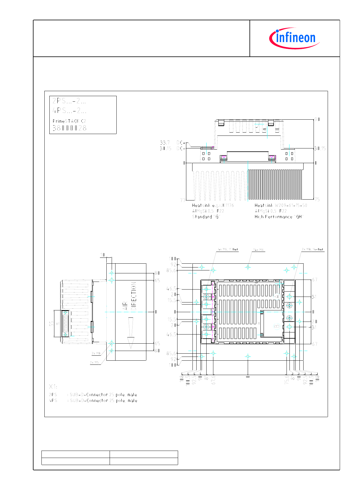
Torque at DC Terminals
M
DC
6,0
10,0
Nm
Torque at AC Terminals
M
AC
16,0
20,0
Nm
Dimensions
width × depth × height
216
200
167
mm
Weight with heat sink
approximation
6,3
kg
Weight without heat sink
approximation
1,9
kg
4
TechnicalInformation
2PS06017E32G28213
PrimeSTACK™
preparedby:OW
approvedby:AR
dateofpublication:2013-05-03
revision:2.0
Preliminarydata
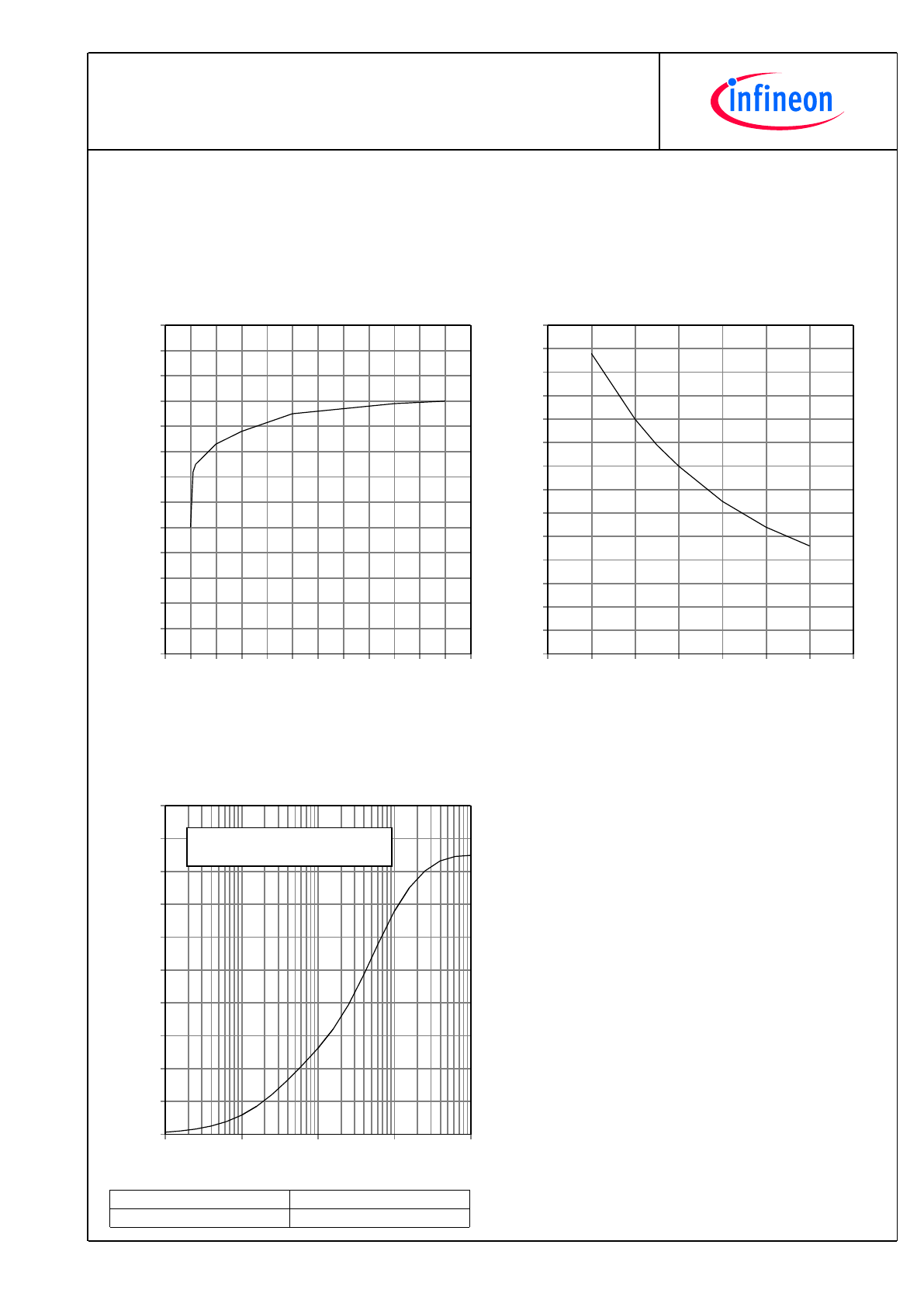
fo - derating curve IGBT (motor)
cos(phi) = 0,85
T
cool medium
= 40°C
f
0
[Hz]
I/I
norm
[%]
-5
0
5
10 15 20 25 30 35 40 45 50 55
0
10
20
30
40
50
60
70
80
90
100
110
120
130
fsw - derating curve IGBT (motor)
cos(phi) = 0,85
T
cool medium
= 40°C
f
sw
[Hz]
I/I
norm
[%]
0
1000
2000
3000
4000
5000
6000
7000
0
10
20
30
40
50
60
70
80
90
100
110
120
130
140
Transient thermal impedance per switch
T
cool medium
= 40°C
time [s]
Zth heat sink to ambient [K/W]
0.1
1
10
100
1000
0.00
0.02
0.04
0.06
0.08
0.10
0.12
0.14
0.16
0.18
0.20
i:
r
i
[K/W]:
τ
i
[s]:
1
0.03136
2.869
2
0.08562
41.23
3
0.03032
145.58
4
0.02254
145.58
5
TechnicalInformation
2PS06017E32G28213
PrimeSTACK™
preparedby:OW
approvedby:AR
dateofpublication:2013-05-03
revision:2.0
Preliminarydata
Mechanicaldrawing
6
TechnicalInformation
2PS06017E32G28213
PrimeSTACK™
preparedby:OW
approvedby:AR
dateofpublication:2013-05-03
revision:2.0
Preliminarydata
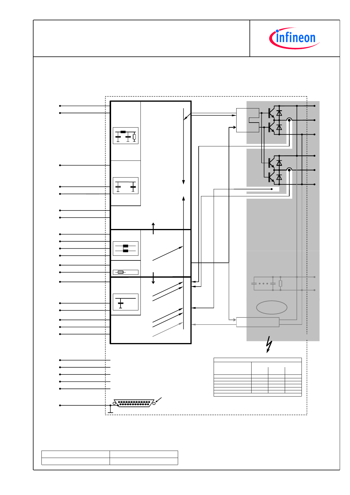
Circuitdiagram
+
-
A
+
-
B
IGBT BOT
Output
Input
14
15 IGBT TOP
2 Error
3
22
Temp. error
Voltage error
13
25
GND digital
GND digital
Digita
l circuit
12
23
10
11
24
NC
NC
NC
NC
1 True earth/shield
Anal
og
circ
uit
20
19
21
Current
Temperature
Voltage DC-Link
7
8
9
GND analog
GND analog
GND analog
Output
Power
sup
ply
6
18
4
16
13V÷30V
GND
GND
13V÷30V
In
Out
15V/50mA
15V/50mA
5
17
Overcurrent
HB A
Overcurrent
HB B
Und
ervolta
ge
Overtemp
. output
stage
Overtemp
. PCB
Overvolta
ge
DC
-Link
Error
me
ssages
Error
me
ssages
Option V
Voltage measurement
V
CE(sat)
/ supply
PTC
X= high level with required external pull up resistor.
Error Table
X
Undervoltage power supply
X
X
Overvoltage DC-Link (Option)
X
Overtemperature PCB
X
X
Overtemperature output stage
X
Overcurrent
X
Error Driver Core
Voltage
Pin 22
Temp.
Pin 3
Error
Pin 2
Error outputs (open collector)
Mana
For detailed technical information please refer the PrimeSTACK manual.
safety separation between
high voltage area and
low voltage area
2PS
-C2
-V
-Re
v03
SUB-D-Connector
25pole male
front view
female thread
UNC4/40
1
NC
High voltage
area in grey
J
BOT
TOP
Eic
eDRIV
ER
™
Option DC link capacitors
+
-
7
TechnicalInformation
2PS06017E32G28213
PrimeSTACK™
preparedby:OW
approvedby:AR
dateofpublication:2013-05-03
revision:2.0
Preliminarydata
Terms&Conditionsofusage
Thedatacontainedinthisproductdatasheetisexclusivelyintendedfortechnicallytrainedstaff.Youandyourtechnical
departmentswillhavetoevaluatethesuitabilityoftheproductfortheintendedapplicationandthecompletenessoftheproduct
datawithrespecttosuchapplication.
Thisproductdatasheetisdescribingthecharacteristicsofthisproductforwhichawarrantyisgranted.Anysuchwarrantyis
grantedexclusivelypursuantthetermsandconditionsofthesupplyagreement.Therewillbenoguaranteeofanykindforthe
productanditscharacteristics.
Shouldyourequireproductinformationinexcessofthedatagiveninthisproductdatasheetorwhichconcernsthespecific
applicationofourproduct,pleasecontactthesalesoffice,whichisresponsibleforyou(seewww.infineon.com,sales&contact).
Forthosethatarespecificallyinterestedwemayprovideapplicationnotes.
Duetotechnicalrequirementsourproductmaycontaindangeroussubstances.Forinformationonthetypesinquestionplease
contactthesalesoffice,whichisresponsibleforyou.
ShouldyouintendtousetheProductinaviationapplications,inhealthorliveendangeringorlifesupportapplications,please
notify.Pleasenote,thatforanysuchapplicationsweurgentlyrecommend
-toperformjointRiskandQualityAssessments;
-theconclusionofQualityAgreements;
-toestablishjointmeasuresofanongoingproductsurvey,
andthatwemaymakedeliverydependedontherealization
ofanysuchmeasures.
Ifandtotheextentnecessary,pleaseforwardequivalentnoticestoyourcustomers.
Changesofthisproductdatasheetarereserved.
SafetyInstructions
Priortoinstallationandoperation,allsafetynoticesandwarningsandallwarningsignsattachedtotheequipmenthavetobe
carefullyread.Makesurethatallwarningsignsremaininalegibleconditionandthatmissingordamagedsignsarereplaced.To
installationandoperation,allsafetynoticesandwarningsandallwarningsignsattachedtotheequipmenthavetobecarefully
read.Makesurethatallwarningsignsremaininalegibleconditionandthatmissingordamagedsignsarereplaced.