

SMSC USB2412
DATASHEET
Revision 1.3 (12-27-11)
Datasheet
PRODUCT FEATURES
USB2412
2-Port USB 2.0 Hi-Speed
Hub Controller
General Description
The SMSC USB2412 hub is a low-power, single
transaction translator (STT) hub controller IC with two
downstream ports for embedded USB applications. The
SMSC hub controller supports low-speed, full-speed,
and hi-speed (if operating as a hi-speed hub)
downstream devices on all of the enabled downstream
ports.
Features
Fully integrated USB termination and pull-up/pull-
down resistors
Supports a single external 3.3 V supply source;
internal regulators provide 1.2 V internal core voltage
On-chip 24 MHz crystal driver or external 24 MHz
clock input
ESD protection up to 4 kilovolts on all USB pins
Supports self-powered operation
Contains a built-in default configuration; no external
configuration options or components are required
Downstream ports as optional non-removable ports
Supports compound devices on a port-by-port basis
28-pin QFN (5 x 5 mm) lead-free RoHS compliant
package
Supports the commercial temperature range:
0ºC to +70ºC
Highlights
High performance, low-power, small footprint hub
controller IC with two downstream ports
Fully compliant with the USB 2.0 Specification
1.
28QFN low pin count package
Optimized for minimal bill-of-materials and low cost
designs
Applications
Automobile/home audio systems
Cable/DSL modems
Embedded systems
Gaming consoles
HDD enclosures
IP telephony
KVM switches
LCD monitors and TVs
Multi-function USB peripherals
Mobile PC docking
PC motherboards
PC media drive bay
Portable hub boxes
Point-of-Sale (POS) systems
Printers and scanners
Server front panels
Set-top boxes, DVD players, DVR/PVR
Thin client terminals
Order Numbers:
This product meets the halogen maximum concentration values per IEC61249-2-21
For RoHS compliance and environmental information, please visit
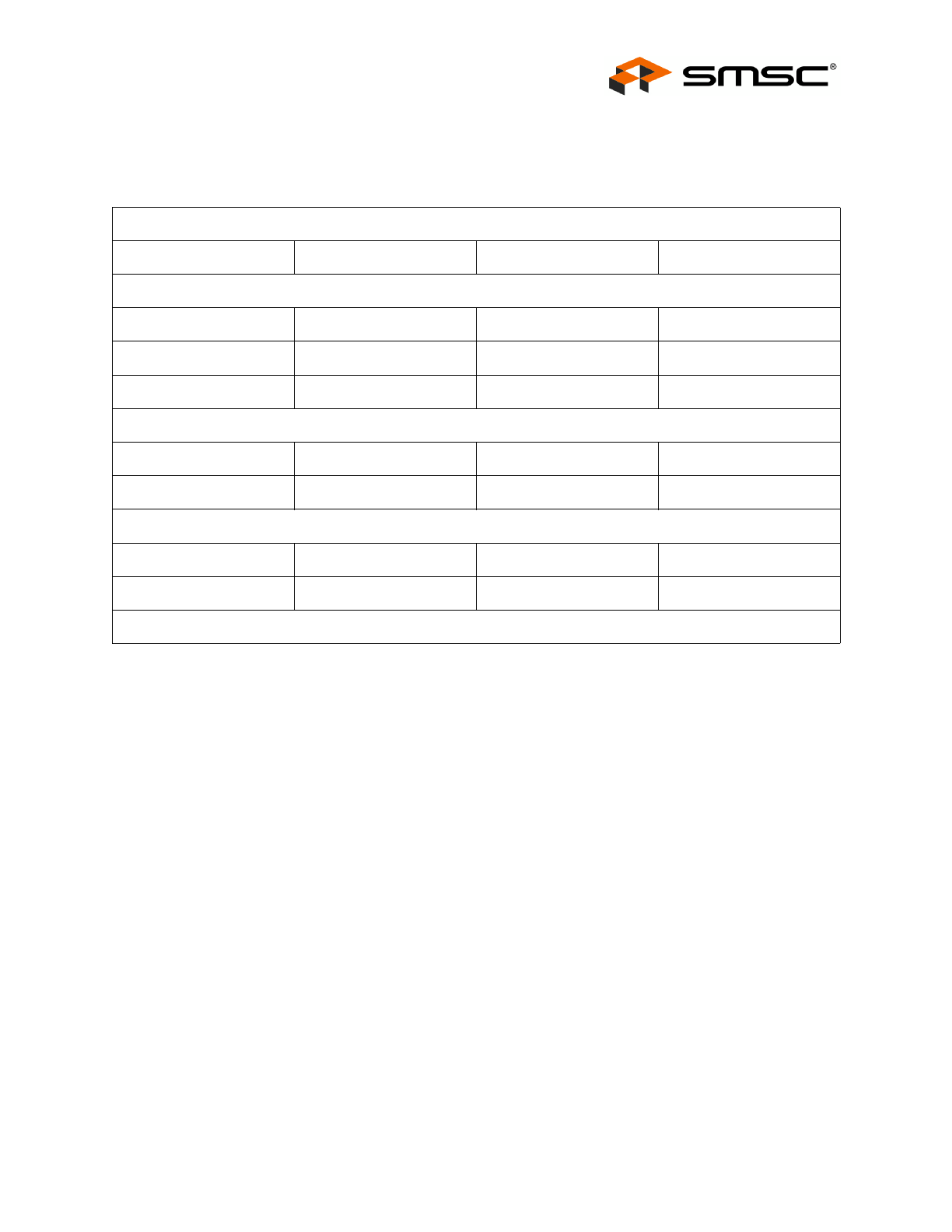
ORDER NUMBERS
*
LEAD-FREE
ROHS COMPLIANT
PACKAGE
PACKAGE SIZE
REEL SIZE
USB2412-DZK
28-Pin QFN Lead-Free, RoHS
Compliant Package
(includes tape and reel option)
5 x 5 x 0.5 mm
-
USB2412-DZK-TR
2-Port USB 2.0 Hi-Speed Hub Controller
Datasheet
Revision 1.3 (12-27-11)
2
SMSC USB2412
DATASHEET
80 ARKAY DRIVE, HAUPPAUGE, NY 11788 (631) 435-6000 or 1 (800) 443-SEMI
Copyright © 2011 SMSC or its subsidiaries. All rights reserved.
Circuit diagrams and other information relating to SMSC products are included as a means of illustrating typical applications. Consequently, complete information sufficient for
construction purposes is not necessarily given. Although the information has been checked and is believed to be accurate, no responsibility is assumed for inaccuracies. SMSC
reserves the right to make changes to specifications and product descriptions at any time without notice. Contact your local SMSC sales office to obtain the latest specifications
before placing your product order. The provision of this information does not convey to the purchaser of the described semiconductor devices any licenses under any patent
rights or other intellectual property rights of SMSC or others. All sales are expressly conditional on your agreement to the terms and conditions of the most recently dated
version of SMSC's standard Terms of Sale Agreement dated before the date of your order (the "Terms of Sale Agreement"). The product may contain design defects or errors
known as anomalies which may cause the product's functions to deviate from published specifications. Anomaly sheets are available upon request. SMSC products are not
designed, intended, authorized or warranted for use in any life support or other application where product failure could cause or contribute to personal injury or severe property
damage. Any and all such uses without prior written approval of an Officer of SMSC and further testing and/or modification will be fully at the risk of the customer. Copies of
this document or other SMSC literature, as well as the Terms of Sale Agreement, may be obtained by visiting SMSC’s website at http://www.smsc.com. SMSC is a registered
trademark of Standard Microsystems Corporation (“SMSC”). Product names and company names are the trademarks of their respective holders.
SMSC DISCLAIMS AND EXCLUDES ANY AND ALL WARRANTIES, INCLUDING WITHOUT LIMITATION ANY AND ALL IMPLIED WARRANTIES OF MERCHANTABILITY,
FITNESS FOR A PARTICULAR PURPOSE, TITLE, AND AGAINST INFRINGEMENT AND THE LIKE, AND ANY AND ALL WARRANTIES ARISING FROM ANY COURSE
OF DEALING OR USAGE OF TRADE. IN NO EVENT SHALL SMSC BE LIABLE FOR ANY DIRECT, INCIDENTAL, INDIRECT, SPECIAL, PUNITIVE, OR CONSEQUENTIAL
DAMAGES; OR FOR LOST DATA, PROFITS, SAVINGS OR REVENUES OF ANY KIND; REGARDLESS OF THE FORM OF ACTION, WHETHER BASED ON CONTRACT;
TORT; NEGLIGENCE OF SMSC OR OTHERS; STRICT LIABILITY; BREACH OF WARRANTY; OR OTHERWISE; WHETHER OR NOT ANY REMEDY OF BUYER IS HELD
TO HAVE FAILED OF ITS ESSENTIAL PURPOSE, AND WHETHER OR NOT SMSC HAS BEEN ADVISED OF THE POSSIBILITY OF SUCH DAMAGES.
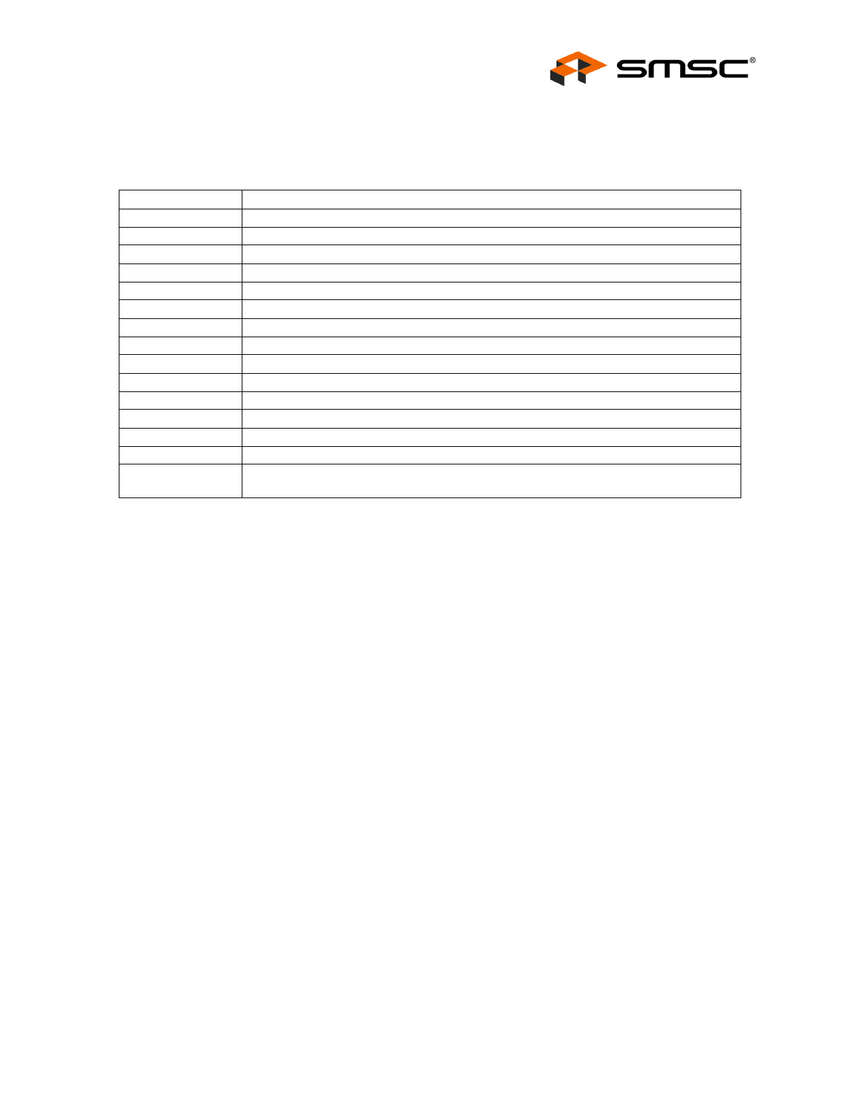
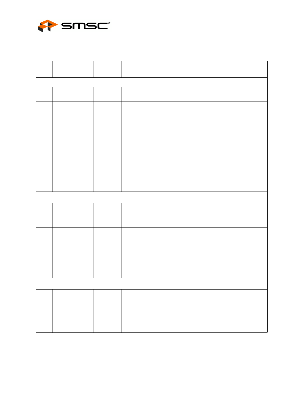
Conventions
Within this manual, the following abbreviations and symbols are used to improve readability.
Example
Description
BIT
Name of a single bit within a field
FIELD.BIT
Name of a single bit (BIT) in FIELD
x…y
Range from x to y, inclusive
BITS[m:n]
Groups of bits from m to n, inclusive
PIN
Pin Name
zzzzb
Binary number (value zzzz)
0xzzz
Hexadecimal number (value zzz)
zzh
Hexadecimal number (value zz)
rsvd
Reserved memory location. Must write 0, read value indeterminate
code
Instruction code, or API function or parameter
Section Name
Section or Document name
x
Don’t care
<Parameter>
<> indicate a Parameter is optional or is only used under some conditions
{,Parameter}
Braces indicate Parameter(s) that repeat one or more times
[Parameter]
Brackets indicate a nested Parameter. This Parameter is not real and actually decodes
into one or more real parameters.
2-Port USB 2.0 Hi-Speed Hub Controller
Datasheet
SMSC USB2412
3
Revision 1.3 (12-27-11)
DATASHEET

2-Port USB 2.0 Hi-Speed Hub Controller
Datasheet
Revision 1.3 (12-27-11)
4
SMSC USB2412
DATASHEET
Table of Contents
Chapter 1 Block Diagram . . . . . . . . . . . . . . . . . . . . . . . . . . . . . . . . . . . . . . . . . . . . . . . . . . . . . 7
Chapter 2 Pin Descriptions . . . . . . . . . . . . . . . . . . . . . . . . . . . . . . . . . . . . . . . . . . . . . . . . . . . . 8
2.1
Pin Configuration . . . . . . . . . . . . . . . . . . . . . . . . . . . . . . . . . . . . . . . . . . . . . . . . . . . . . . . . . . . . . . . 8
2.2
28-Pin Table . . . . . . . . . . . . . . . . . . . . . . . . . . . . . . . . . . . . . . . . . . . . . . . . . . . . . . . . . . . . . . . . . . . 9
2.3
Pin Descriptions (Grouped by Function). . . . . . . . . . . . . . . . . . . . . . . . . . . . . . . . . . . . . . . . . . . . . 10
2.4
Buffer Type Descriptions . . . . . . . . . . . . . . . . . . . . . . . . . . . . . . . . . . . . . . . . . . . . . . . . . . . . . . . . 12
2.5
Strap Option Pins . . . . . . . . . . . . . . . . . . . . . . . . . . . . . . . . . . . . . . . . . . . . . . . . . . . . . . . . . . . . . . 12
Chapter 3 Internal Default Configuration. . . . . . . . . . . . . . . . . . . . . . . . . . . . . . . . . . . . . . . 14
3.1
Hub Configuration. . . . . . . . . . . . . . . . . . . . . . . . . . . . . . . . . . . . . . . . . . . . . . . . . . . . . . . . . . . . . . 14
3.2
Reset . . . . . . . . . . . . . . . . . . . . . . . . . . . . . . . . . . . . . . . . . . . . . . . . . . . . . . . . . . . . . . . . . . . . . . . 14
3.2.1
External Hardware RESET_N . . . . . . . . . . . . . . . . . . . . . . . . . . . . . . . . . . . . . . . . . . . . . 14
3.2.2
USB Bus Reset . . . . . . . . . . . . . . . . . . . . . . . . . . . . . . . . . . . . . . . . . . . . . . . . . . . . . . . . 15
Chapter 4 DC Parameters. . . . . . . . . . . . . . . . . . . . . . . . . . . . . . . . . . . . . . . . . . . . . . . . . . . . 16
4.1
Maximum Guaranteed Ratings . . . . . . . . . . . . . . . . . . . . . . . . . . . . . . . . . . . . . . . . . . . . . . . . . . . . 16
4.2
Operating Conditions . . . . . . . . . . . . . . . . . . . . . . . . . . . . . . . . . . . . . . . . . . . . . . . . . . . . . . . . . . . 16
4.2.1
Pin Capacitance . . . . . . . . . . . . . . . . . . . . . . . . . . . . . . . . . . . . . . . . . . . . . . . . . . . . . . . 19
4.2.2
Package Thermal Specifications . . . . . . . . . . . . . . . . . . . . . . . . . . . . . . . . . . . . . . . . . . . 19
Chapter 5 AC Specifications . . . . . . . . . . . . . . . . . . . . . . . . . . . . . . . . . . . . . . . . . . . . . . . . . . 20
5.1
Oscillator/Crystal. . . . . . . . . . . . . . . . . . . . . . . . . . . . . . . . . . . . . . . . . . . . . . . . . . . . . . . . . . . . . . . 20
5.2
External Clock. . . . . . . . . . . . . . . . . . . . . . . . . . . . . . . . . . . . . . . . . . . . . . . . . . . . . . . . . . . . . . . . . 21
5.2.1
USB 2.0 . . . . . . . . . . . . . . . . . . . . . . . . . . . . . . . . . . . . . . . . . . . . . . . . . . . . . . . . . . . . . . 21
Chapter 6 Package Outline . . . . . . . . . . . . . . . . . . . . . . . . . . . . . . . . . . . . . . . . . . . . . . . . . . . 22
6.1
Tape and Reel Specification. . . . . . . . . . . . . . . . . . . . . . . . . . . . . . . . . . . . . . . . . . . . . . . . . . . . . . 24

2-Port USB 2.0 Hi-Speed Hub Controller
Datasheet
SMSC USB2412
5
Revision 1.3 (12-27-11)
DATASHEET
List of Figures
Figure 1.1 USB2412 Block Diagram . . . . . . . . . . . . . . . . . . . . . . . . . . . . . . . . . . . . . . . . . . . . . . . . . . . . . 7
Figure 2.1 USB2412 28-Pin QFN . . . . . . . . . . . . . . . . . . . . . . . . . . . . . . . . . . . . . . . . . . . . . . . . . . . . . . . 8
Figure 2.2 Non-Removable Pin Strap Example . . . . . . . . . . . . . . . . . . . . . . . . . . . . . . . . . . . . . . . . . . . 12
Figure 2.3 LED Pin Strap Example . . . . . . . . . . . . . . . . . . . . . . . . . . . . . . . . . . . . . . . . . . . . . . . . . . . . . 13
Figure 3.1 Reset_N Timing . . . . . . . . . . . . . . . . . . . . . . . . . . . . . . . . . . . . . . . . . . . . . . . . . . . . . . . . . . . 15
Figure 4.1 Supply Rise Time Model . . . . . . . . . . . . . . . . . . . . . . . . . . . . . . . . . . . . . . . . . . . . . . . . . . . . 17
Figure 5.1 Typical Crystal Circuit . . . . . . . . . . . . . . . . . . . . . . . . . . . . . . . . . . . . . . . . . . . . . . . . . . . . . . 20
Figure 5.2 Formula to Find the Value of C1 and C2 . . . . . . . . . . . . . . . . . . . . . . . . . . . . . . . . . . . . . . . . 20
Figure 6.1 USB2412 28-Pin QFN Package Outline (5x5 mm Body, 0.5 Pitch, 3.1 ePad). . . . . . . . . . . . 22
Figure 6.2 Recommended Printed Circuit Board (PCB) Land Pattern . . . . . . . . . . . . . . . . . . . . . . . . . . 23
Figure 6.3 28-Pin Package Tape Dimensions and Part Orientation (mm) . . . . . . . . . . . . . . . . . . . . . . . 24
Figure 6.4 28-Pin Package Tape Length and Part Quantity . . . . . . . . . . . . . . . . . . . . . . . . . . . . . . . . . . 24
Figure 6.5 Package Reel Specifications . . . . . . . . . . . . . . . . . . . . . . . . . . . . . . . . . . . . . . . . . . . . . . . . . 25

2-Port USB 2.0 Hi-Speed Hub Controller
Datasheet
Revision 1.3 (12-27-11)
6
SMSC USB2412
DATASHEET
List of Tables
Table 2.1 USB2412 28-Pin Table . . . . . . . . . . . . . . . . . . . . . . . . . . . . . . . . . . . . . . . . . . . . . . . . . . . . . . . 9
Table 2.2 USB2412 Pin Descriptions . . . . . . . . . . . . . . . . . . . . . . . . . . . . . . . . . . . . . . . . . . . . . . . . . . . 10
Table 2.3 Buffer Type Descriptions . . . . . . . . . . . . . . . . . . . . . . . . . . . . . . . . . . . . . . . . . . . . . . . . . . . . . 12
Table 3.1 Reset_N Timing . . . . . . . . . . . . . . . . . . . . . . . . . . . . . . . . . . . . . . . . . . . . . . . . . . . . . . . . . . . . 15
Table 4.1 DC Electrical Characteristics . . . . . . . . . . . . . . . . . . . . . . . . . . . . . . . . . . . . . . . . . . . . . . . . . . 17
Table 4.2 Pin Capacitance. . . . . . . . . . . . . . . . . . . . . . . . . . . . . . . . . . . . . . . . . . . . . . . . . . . . . . . . . . . . 19
Table 4.3 28-Pin QFN Package Thermal Parameters . . . . . . . . . . . . . . . . . . . . . . . . . . . . . . . . . . . . . . . 19
Table 5.1 Crystal Circuit Legend . . . . . . . . . . . . . . . . . . . . . . . . . . . . . . . . . . . . . . . . . . . . . . . . . . . . . . . 20
Table 6.1 Package Parameters . . . . . . . . . . . . . . . . . . . . . . . . . . . . . . . . . . . . . . . . . . . . . . . . . . . . . . . . 22
2-Port USB 2.0 Hi-Speed Hub Controller
Datasheet
SMSC USB2412
7
Revision 1.3 (12-27-11)
DATASHEET
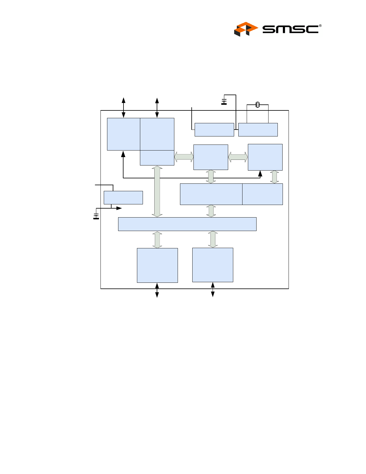
Chapter 1 Block Diagram
Figure 1.1 USB2412 Block Diagram
To Upstream
V
BUS
3.3 V
Upstream
PHY
Upstream
USB Data
Repeater
Controller
Serial
Interface
Engine
Port
Controller
Bus-
Power
Detect/
V
bus
Pulse
PHY#1
Transaction
Translator
USB Data
Downstream
USB Data
Downstream
3.3 V
PLL
24 MHz
Crystal
Routing & Port Re-Ordering Logic
Regulator
CRFILT
Regulator
PHY#2
2-Port USB 2.0 Hi-Speed Hub Controller
Datasheet
Revision 1.3 (12-27-11)
8
SMSC USB2412
DATASHEET
Chapter 2 Pin Descriptions
This chapter is organized by a set of pin configurations followed by a corresponding pin list organized
by function according to their associated interface. A detailed description list of each signal (named in
the pin list) is organized by function in
Table 2.2, “USB2412 Pin Descriptions,” on page 10
. Refer to
Table 2.3, “Buffer Type Descriptions,” on page 12
for a list of buffer types.
The “N” symbol in the signal name indicates that the active, or asserted, state occurs when the signal
is at a low voltage level. When “N” is not present after the signal name, the signal is asserted when it
is at the high voltage level.
The terms assertion and negation are used exclusively. This is done to avoid confusion when working
with a mixture of “active low” and “active high” signals. The term assert, or assertion, indicates that a
signal is active, independent of whether that level is represented by a high or low voltage. The term
negate, or negation, indicates that a signal is inactive.
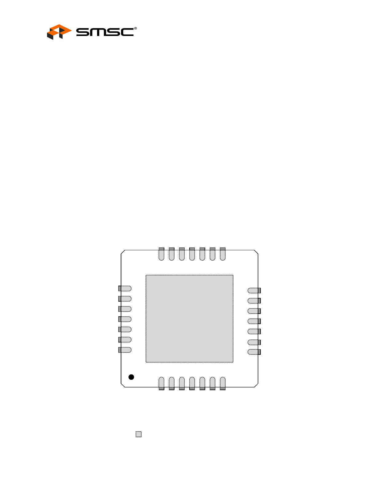
2.1
Pin Configuration
Figure 2.1 USB2412 28-Pin QFN
Ground Pad
(must be connected to VSS)
SMSC
USB2412
(Top View QFN-28)
XTALOUT
23
XTALIN/CLKIN
24
USBDP_UP
22
PLLFILT
25
RBIAS
26
USBDM_DN1
28
VDD33
27
NC
1
US
B
D
P_
D
N
1
2
USBD
M
_DN
2
3
US
B
D
P_
D
N
2
4
VD
D
33
5
TE
ST
6
PR
TP
WR
1
7
14
VDD33
13
NON_REM1
12
VDD33
11
OCS_N2
10
PRTPWR2
9
CRFILT
8
OCS_N1
21
USBD
M
_UP
20
VDD
33
19
SU
SP_IND/N
O
N
_REM
0
18
VBUS
_DET
17
RESET_N
16
HS_I
N
D
15
TE
ST
1
Indicates pins on the bottom of the device.
2-Port USB 2.0 Hi-Speed Hub Controller
Datasheet
SMSC USB2412
9
Revision 1.3 (12-27-11)
DATASHEET
2.2
28-Pin Table
Table 2.1 USB2412 28-Pin Table
UPSTREAM USB 2.0 INTERFACES (3 PINS)
USBDP_UP
USBDM_UP
VBUS_DET
DOWNSTREAM 2-PORT USB 2.0 INTERFACES (9 PINS)
USBDP_DN1
USBDM_DN1
USBDP_DN2
USBDM_DN2
PRT_PWR1
PRT_PWR2
OCS_N1
OCS_N2
RBIAS
MISC (7 PINS)
RESET_N
TEST
XTALIN / CLKIN
XTALOUT
NON_REM1
SUSP_IND / NON_REM0
HS_IND
POWER, GROUND, AND NO CONNECTS (9 PINS)
(5) VDD33
CRFILT
PLLFILT
VSS
NC
TOTAL 28
2-Port USB 2.0 Hi-Speed Hub Controller
Datasheet
Revision 1.3 (12-27-11)
10
SMSC USB2412
DATASHEET
2.3
Pin Descriptions (Grouped by Function)
Table 2.2 USB2412 Pin Descriptions
PIN
#
SYMBOL
BUFFER
TYPE
DESCRIPTION
UPSTREAM USB 2.0 INTERFACES
21
22
USBDM_UP
USBDP_UP
IO-U
USB Bus Data: connect to the upstream USB bus data signals (host,
port, or upstream hub).
18
VBUS_DET
I/O12
Detect Upstream VBUS Power: detects the state of upstream VBUS
power. The SMSC hub monitors VBUS_DET to determine when to
assert the internal D+ pull-up resistor which signals a connect event.
When designing a detachable hub, this pin should be connected to
VBUS on the upstream port via a 2 to 1 voltage divider.
For self-powered applications with a permanently attached host, this
pin must be connected to a dedicated host control output, or
connected to 3.3 V domain that powers the host.‘
According to Section 7.2.1 of the USB 2.0 Specification
1.
, a
downstream port can never provide power to its D+ or D- pull-up
resistors unless the upstream port’s VBUS is in the asserted (powered)
state.
VBUS_DET monitors the state of the upstream VBUS signal and will
not pull-up the D+ resistor if VBUS is not active. If VBUS goes from
an active to an inactive state (Not Powered), the hub will remove
power from the D+ pull-up resistor within 10 seconds.
DOWNSTREAM USB 2.0 INTERFACES
1
3
28
2
USBDP_DN1
USBDP_DN2
USBDM_DN1
USBDM_DN2
IO-U
Hi-Speed USB Data: connect to the downstream USB peripheral
devices attached to the hub’s ports.
7
11
PRTPWR1
PRTPWR2
I/O12
USB Power Enable: enables power to USB peripheral devices that are
downstream, where the hub supports active high power controllers
only.
8
12
OCS_N1
OCS_N2
IPU
Over-Current Sense: input from external current monitor indicating an
over-current condition. This pin contains an internal pull-up to the 3.3 V
supply.
26
RBIAS
I-R
USB Transceiver Bias: a 12.0 k
Ω (+/- 1%) resistor is attached from
ground to this pin to set the transceiver’s internal bias settings.
MISC
13
NON_REM1
I/O
Non-removable Port Strap Option: this pin is sampled (in conjunction
with SUSP_IND/NON_REM0) at RESET_N negation to determine if
ports [2:1] contain permanently attached (non-removable) devices:
NON_REM[1:0] = 00: all ports are removable
NON_REM[1:0] = 01: port 1 is non-removable
NON_REM[1:0] = 10 and 11: ports 1 and 2 are non-removable
See
Section 2.5, "Strap Option Pins"
for details.