
Features
• Companion Chip to CryptoRF
®
and CryptoMemory
®
⎯ Securely implements host algorithms
⎯ Securely stores host secrets
⎯ Verifies Host Firmware Digests
• High Security Features in Hardware
⎯ CryptoMemory and CryptoRF F2 Algorithm
⎯ SHA-1 Standard Cryptographic Algorithm
⎯ 64-bit Mutual Authentication Protocol (Under License of ELVA)
⎯ Permanently Coded Serial Numbers
⎯ High Quality Random Number Generator (RNG)
⎯ Metal Shield Over Memory
⎯ Data Scrambling in Nonvolatile Memory
⎯ Delay Penalties to prevent Systematic Attacks
⎯ Reset Locking to prevent Illegal Power Cycling
⎯ Voltage and Frequency Monitors
• Host-side Crypto Functions
⎯ Authentication Challenge Generation
⎯ Device Challenge Response
⎯ Message Authentication Codes (MAC) Generation
⎯ Data Encryption and Decryption
⎯ Secure Authentication Key Management
• Secure Storage and Key Management
⎯ Up to 16 sets of 64-bits Diversified Host Keys
⎯ Eight Sets of Two 24-bit Passwords
⎯ Secure and Custom Personalization
⎯ Up to 232-Byte Read/Write Configurable User Data Area
• Nonvolatile Up Counters
⎯ Four sets Unidirectional Counters
⎯ 6.4 Million Maximum Counts Per Counter
• Application Features
⎯ Low Voltage Supply: 2.7V – 3.6V
⎯ 2-Wire Serial Interface (TWI, 5V Compatible)
⎯ Standard 8-lead SOIC Plastic Package, Green compliant (exceeds RoHS)
• High Reliability
⎯ Endurance
: 100,000 Cycles
⎯ Data Retention : 10 years
⎯ ESD Protection : 3,000 V min. HBM
CryptoCompanion
™
Chip for
CryptoMemory and
CryptoRF
AT88SC018
Summary
5277DS–CryptoCompanion–9/09

2
CryptoCompanion
™ Chip
5277DS–CryptoCompanion–9/09
1. Product
Overview
The CryptoCompanion™ Chip is designed as the mate to Atmel’s CryptoRF and CryptoMemory chips, collectively
referred to in the remainder of this document as CRF.
CryptoCompanion makes extensive use of the SHA-1 hash algorithm as specified in
http://www.itl.nist.gov/fipspubs/fip180-1.htm
and elsewhere. In this document, the nomenclature SHA-1(a, b, c) means
to concatenate a, b & c in that order and then pad them to a block size of 64 bytes before computing the digest.
CryptoCompanion generates SHA-1 digests of single round datasets at a time.
1.1. General
Operation
The CRF chip contains secrets that must be known or derived by a host system in order to establish a trusted link
between the two and permit communications to happen. CryptoCompanion stores these secrets in an obscured way in
nonvolatile memory and contains all the circuitry necessary to perform the authentication, password and
encryption/decryption functions specified in the CRF datasheet. In this manner, the secrets do not ever need to be
revealed.
The general cryptographic strategy is as follows:
• Each CRF chip has a serial or identification number (ID) and authentication secret G
i
stored in EEPROM. ID is
freely readable while G
i
can never be read and is unique for all tags.
• CryptoCompanion contains an EEPROM that holds a set of common secrets (F
n
). CryptoCompanion combines F
n
with ID and K
ID
to compute a value of G that is expected to match that in the CRF chip. Specifically, G = SHA-1(F
n
,
ID, K
ID
)
•
G is further diversified by the inclusion of a number (K
ID
) generated by the host system in a manner of its choosing.
Typically, it will be the result of a cryptographic operation on the CRF ID value calculated using other data, secrets
and/or algorithms external to CryptoCompanion. This permits scenarios that offer varying degrees of additional
security.
• CryptoCompanion includes a general purpose cryptographic quality random number generator which is used to
seed a mutual authentication process between CryptoCompanion and CRF. If the CRF confirms the
CryptoCompanion challenge, and the CryptoCompanion confirms the CRF response, then the host system
proceeds with CRF operations. In this way the host system may use the CRF without knowing the CRF's secrets
directly.
1.2. CryptoCompanion
Benefits
The following is a partial list of the benefits of using this chip versus storing the algorithms and secrets in standard
FLASH system memory.
• Keep confidential those core secrets that are used to authenticate with and communicate to/from CRF.
(Store them in EEPROM, use them on-chip)
• Flexible system implementation – multiple secrets and policies for different CRF locations within the system.
Multiple manufacturer setup options.
•
Hardware encryption engines, avoids algorithm disclosure from reverse-compilation of system operating code.
• Full hardware security implementation makes it harder for an attacker (even with lab equipment) to get secrets
stored on CryptoCompanion.
•
Global secrets are protected using strong security, standard algorithm (SHA-1).
• Robust random number generation avoids accidental replay for all cryptographic operations using the system, not
just with respect to CRF.
•
Secure EEPROM storage for configuration information, etc. May permit reduction in the total BOM for the system.
•
Easy to use – little programming required; no knowledge of security algorithms or protocols, fast time to market.

CryptoCompanion
™ Chip
3
5277DS–CryptoCompanion–9/09
1.3.
Package, Pin Definition & IO
1.3.1. Pin
Definition
1.3.1.1. V
CC
, Gnd
Power supply is 2.7 – 3.6V. Supply current less than 5 mA.
CryptoCompanion will be available to accept commands 60 ms after the later of V
CC
rising above 2.7V or Reset being
driven high if CryptoCompanion is in a security delay then this interval is significantly longer.
During Power Up, V
CC
must exhibit a monotonic ramp at a minimum rate of 50 mV/mS until V
CC
has crossed the 2.7V
level. During Power Down, V
CC
must exhibit a monotonic ramp at a minimum rate of 50 mV/mS once it has dropped
below the 2.5V boundary. CryptoCompanion does not support hot swapping or hot plugging.
V
CC
must be bypassed with high quality surface mount capacitors that are properly located on the board. Atmel
recommends two capacitors connected in parallel having a value of 1
μF and 0.01μF. The capacitors should be
manufactured using X5R or X7R dielectric material. These capacitors should be connected to CryptoCompanion using
a total of no more than 1cm PC board traces. Atmel recommends the use of a ground plane and a trace length of less
than 0.5cm between the capacitors and the V
CC
pin. Failure to follow these recommendations may result in improper
operation.
1.3.1.2. SDA
Two wire interface data pin, 5 V compatible. Minimum data setup time = 0.1
μs, and minimum data hold time = 0 μs min.
The system board must include an external pull-up resistor.
1.3.1.3. SCL
Two wire interface clock pin, 5 V compatible. Maximum SCL rate is 400KHz, minimum T
LOW
= 1.2
μs, minimum
T
HIGH
= 0.6
μs. The system board must include an external pull-up resistor.
1.3.1.4. Reset
(RST)
This active low input will reset all states within CryptoCompanion. Honored regardless of the state of PowerDown.
1.3.1.5. PowerDown
(PDN)
When held low, the part operates normally. When held high the part will go to sleep and ignore all transitions on SDA
and SCL, power consumption will drop to less than 10
μA. There is a 50 ms delay between this pin falling and the first
transition on SDA or SCL that will be accepted by the chip.
4
CryptoCompanion
™ Chip
5277DS–CryptoCompanion–9/09
1.3.2. Package
CryptoCompanion is packaged in an 8 lead SOIC package with the following pin definition:
Table 1. 8 lead SOIC package pin definition
Pin Number
Pin Name
1 V
CC
5 Gnd
7 SDA
8 SCL
4 RST
3 PDN
2,6 NC
Pins 2 & 6 are not internally connected and should be connected to ground on the PC board.
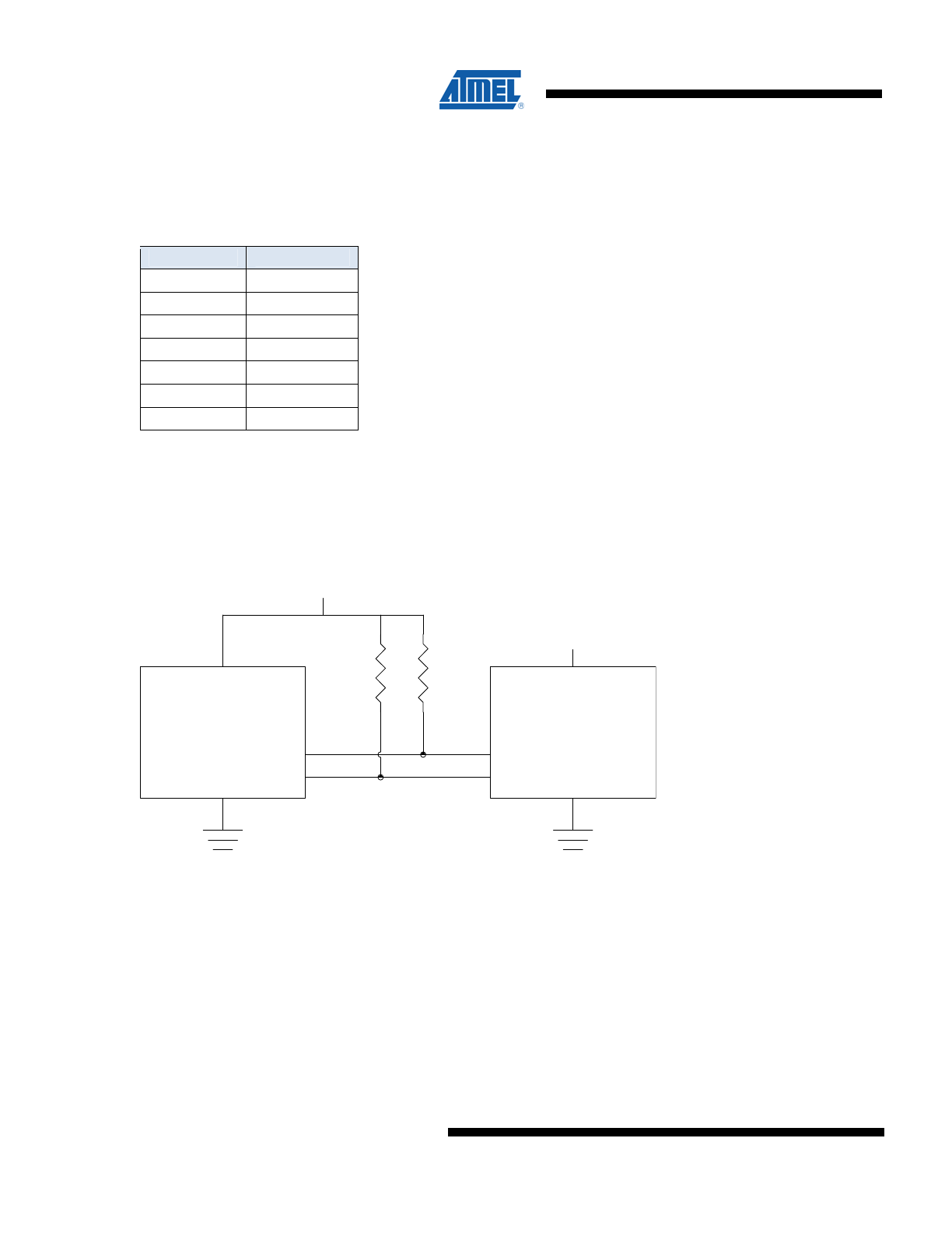
1.3.3.
Connection Diagram
Figure 1. Connection Diagram
2.7v - 5.5v
2.7v - 3.6v
SDA
SCL
Microprocessor
CryptoCompanion
1.3.4. Environmental
CryptoCompanion is guaranteed to operate over the industrial temperature range of -40° to 85° C. ESD is rated at 3KV,
Human Body Model.
1.3.5.
TWI Input/Output Operation
CryptoCompanion communicates to the system using a two wire interface (TWI), which is similar to SMBus. The chip
operates as a slave and does not support clock stretching. This two wire protocol is identical to that supported by the
Atmel AT24C16B serial EEPROM chips. Please see that datasheet on the Atmel web site for detailed timing and
protocol information.
CryptoCompanion
™ Chip
5
5277DS–CryptoCompanion–9/09
The system processor is expected to properly format commands for CryptoCompanion (which may include information
from the CRF chip), and then process the outputs of CryptoCompanion (which may include sending some of the
outputs to the CRF chip).
CryptoCompanion cannot directly communicate with CRF chips. Both CRF and CryptoCompanion are slave devices.
The bus master may use one or two busses to communicate with them. Separate TWI addresses must be used if both
chips are on the same bus.
1.4. Memory
Locking
When this initialization is complete the Lock command should be executed which limits access to the memory per the
restrictions listed later in this section. The system can determine the current lock value by using the
ReadManufacturingID command to read out the ManufacturingID value (MfrID) and the lock byte.
The table below describes the encoding of the least significant two bits of the Lock byte. On shipment from Atmel,
Lock[1:0] will have a value of either 10 or 00, depending on the part number ordered. An AT88SC018 in either of these
two states is considered ‘unlocked’. It is not possible to change from one of these unlocked states to the other.
After the Lock command has been executed, the Lock byte will have the value 0xFF. Subsequent changes to the Lock
byte are impossible.
Table 2. Memory Locking
LockBit 1
Lock Bit 0 (LSB)
Meaning
1
1
Locked. ReadMemory & WriteMemory enabled, subject to the restrictions in this
section. WriteMemoryEncrypted and ReadMemoryDigest disabled.
1 0
Unlocked/Confidential.
ReadMemoryDigest, WriteMemory and
WriteMemoryEncrypted enabled. ReadMemory disabled.
0
0
Unlocked. ReadMemory & WriteMemory enabled. WriteMemoryEncrypted and
ReadMemoryDigest disabled.
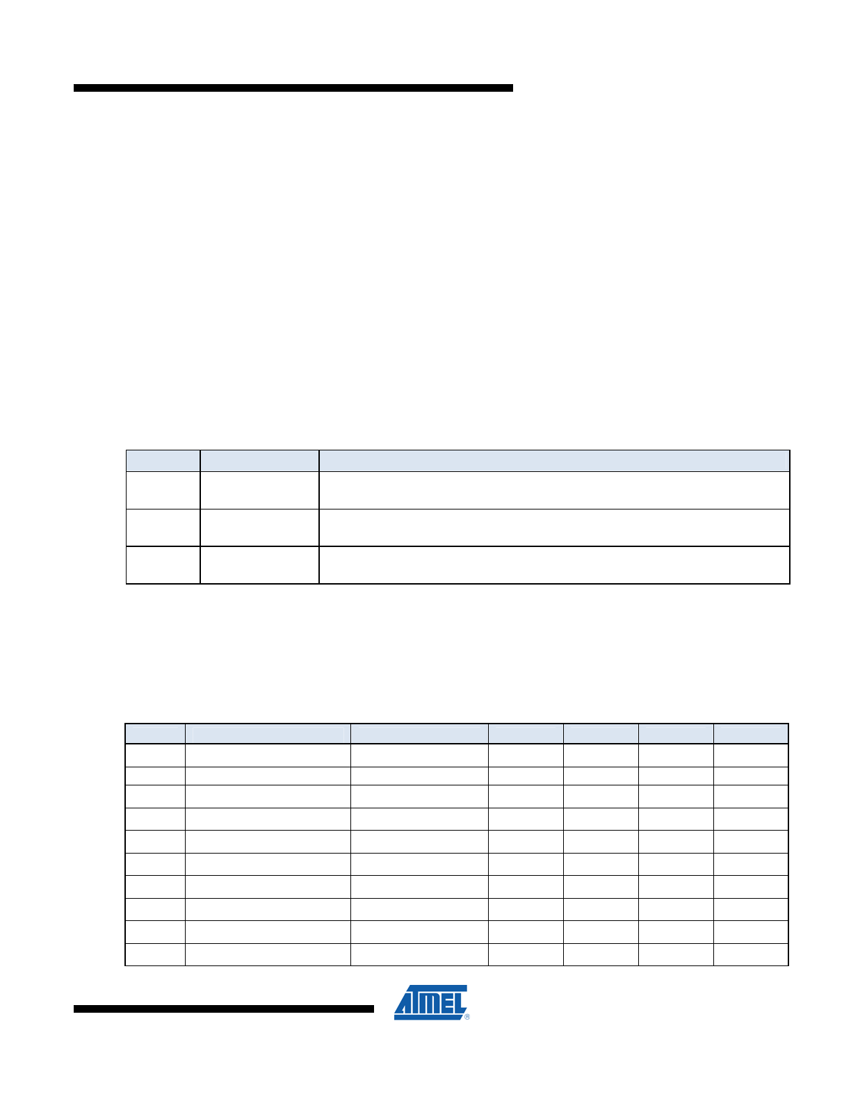
2.
AC & DC Characteristics
Table 3. DC Characteristics
(1)
Applicable over recommended operating range from V
CC
= +2.7 to 3.6 V,
T
AC
= -40
o
C to 85
o
C (unless otherwise noted)
Symbol
Parameter
Test Condition
Min
Typ
Max
Units
V
CC
Supply Voltage
2.7
3.6
V
I
CC
Supply Current
400kHz
5
mA
I
SB
Standby
Current
V
IN
= V
CC
or GND
15
μA
V
IL
SDA Input Low Voltage
-0.3
V
CC
x 0.3
V
V
IL
CLK Input Low Voltage
-0.3
V
CC
x 0.3
V
V
IL
RST Input Low Voltage
-0.3
V
CC
x 0.3
V
V
IL
PDN Input Low Voltage
-0.3
V
CC
x 0.3
V
V
IH
SDA Input High Voltage
V
CC
x 0.7
5.25
V
V
IH
SCL Input High Voltage
V
CC
x 0.7
5.25
V
V
IH
RST Input High Voltage
V
CC
x 0.7
5.25
V
6
CryptoCompanion
™ Chip
5277DS–CryptoCompanion–9/09
V
IH
PDN Input High Voltage
V
CC
x 0.7
5.25
V
I
IL
SDA Input Low Current
0 < V
IL
< V
CC
x 0.15
-10
10
μA
I
IL
SCL Input Low Current
0 < V
IL
< V
CC
x 0.15
-10
10
μA
I
IL
RST Input Low Current
0 < V
IL
< V
CC
x 0.15
-10
10
μA
I
IL
PDN Input Low Current
0 < V
IL
< V
CC
x 0.15
-10
10
μA
I
IH
SDA Input High Current
V
CC
x 0.7 < V
IH
< V
CC
-10
10
μA
I
IH
SCL Input High Current
V
CC
x 0.7 < V
IH
< V
CC
-10
10
μA
I
IH
RST Input High Current
V
CC
x 0.7 < V
IH
< V
CC
-10
10
μA
I
IH
PDN Input High Current
V
CC
x 0.7 < V
IH
< V
CC
-10
10
μA
V
OH
SDA Output High Voltage
20k Ohm external
Pull-up
V
CC
x 0.8
V
V
OL
SDA Output Low Voltage
I
OL
= 1mA
0.4
V
Note: 1. Typical values at 25° C. Maximum values are characterized values and not test limits in production.
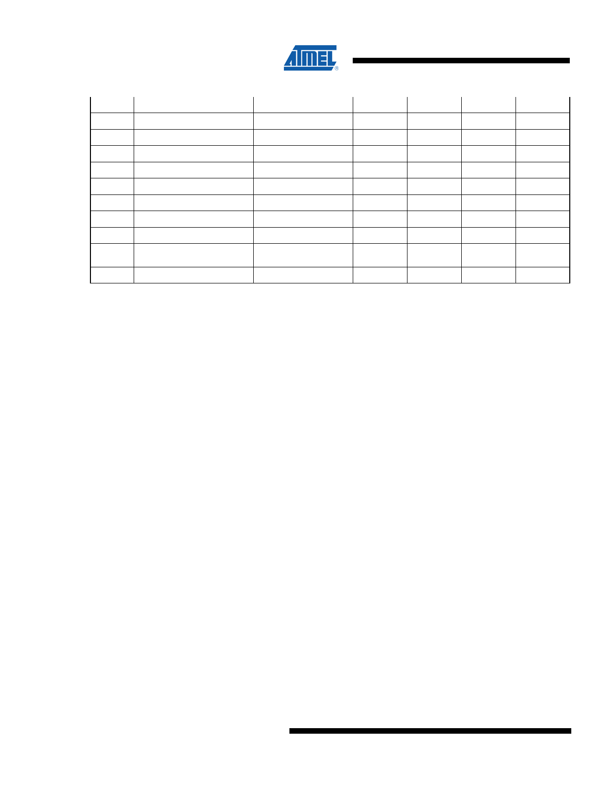
CryptoCompanion
™ Chip
7
5277DS–CryptoCompanion–9/09
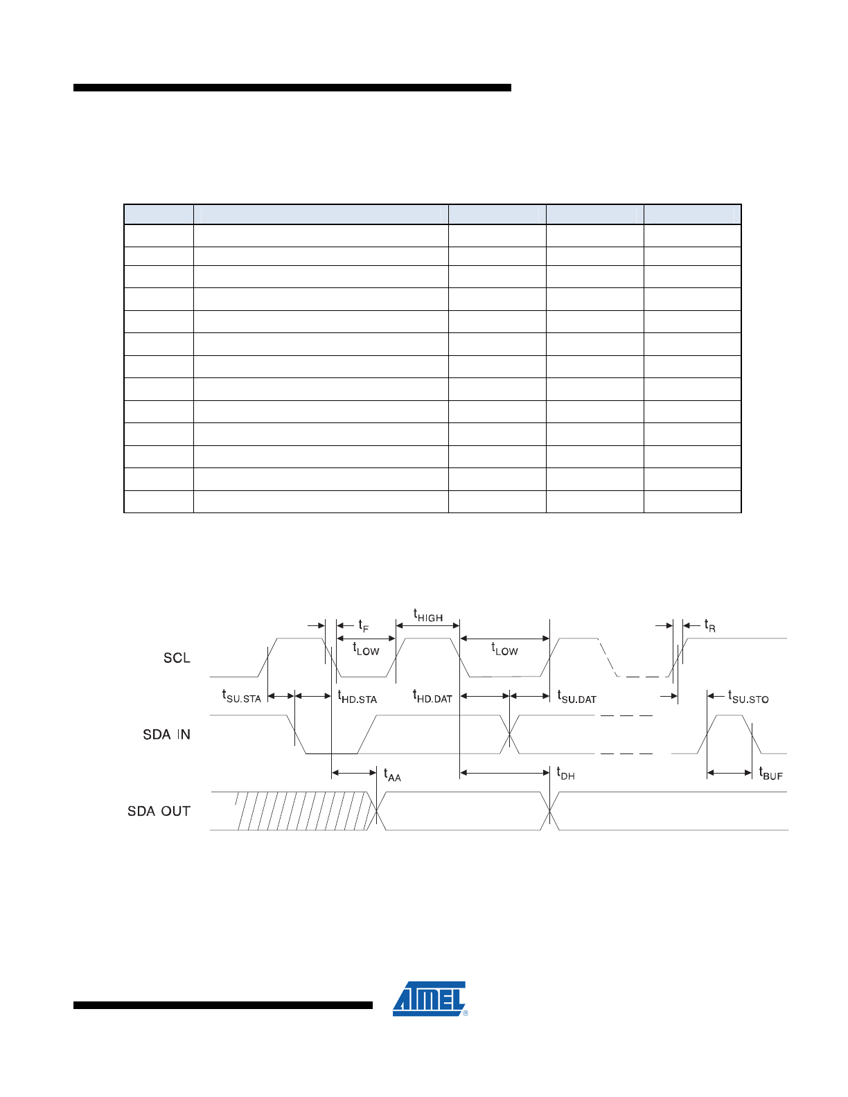
Table 4. AC Characteristics
(1)
Applicable over recommended operating range from V
CC
= +2.7 to 3.6 V,
T
AC
= -40
o
C to 85
o
C, CL = 30pF (unless otherwise noted)
Symbol
Parameter
Min
Max
Units
f
CLK
Clock
Frequency
0
400
kHz
Clock Duty cycle
(2)
40
60
%
t
R
Rise Time - SDA, RST, PDN
(2)
300
nS
t
F
Fall Time - SDA, RST, PDN
(2)
300
nS
t
R
Rise Time - SCL
(2)
300
nS
t
F
Fall Time - SCL
(2)
300
nS
t
AA
Clock Low to Data Out Valid
900
nS
t
HD.STA
Start Hold Time
600
nS
t
SU.STA
Start Set-up Time
600
nS
t
HD.DAT
Data In Hold Time
100
nS
t
SU.DAT
Data In Set-up Time
100
nS
t
SU.STO
Stop Set-up Time
600
nS
t
DH
Data Out Hold Time
50
900
nS
Note: 1. Typical values at 25° C. Maximum values are characterized values and not test limits in production.
2. This parameter is not tested. Values are based on characterization and/or simulation data.
Figure 2. SCL: Serial Clock, SDA: Serial Data I/O®
8
CryptoCompanion
™ Chip
5277DS–CryptoCompanion–9/09
3. Ordering
Codes
Table 5. Ordering Codes
Ordering Code
Package
Voltage
Range
Memory Locking
(see
Section 1.4 for Lock Definitions)
Temperature Range
AT88SC018-SU-CM
8S1
2.7V – 3.6V
00 (Unlocked)
Green compliant (exceeds
RoHS), Industrial (-40
0
C – 85
0
C), Bulk
AT88SC018-SU-CM-T
8S1
2.7V – 3.6V
00 (Unlocked)
Green compliant (exceeds
RoHS), Industrial (-40
0
C – 85
0
C), Tape and Reel
AT88SC018-SU-CN
8S1
2.7V – 3.6V 10
(Unlocked/Confidential)
Green compliant (exceeds
RoHS), Industrial (-40
0
C – 85
0
C), Bulk
AT88SC018-SU-CN-T
8S1
2.7V – 3.6V 10
(Unlocked/Confidential)
Green compliant (exceeds
RoHS), Industrial (-40
0
C – 85
0
C), Tape and Reel
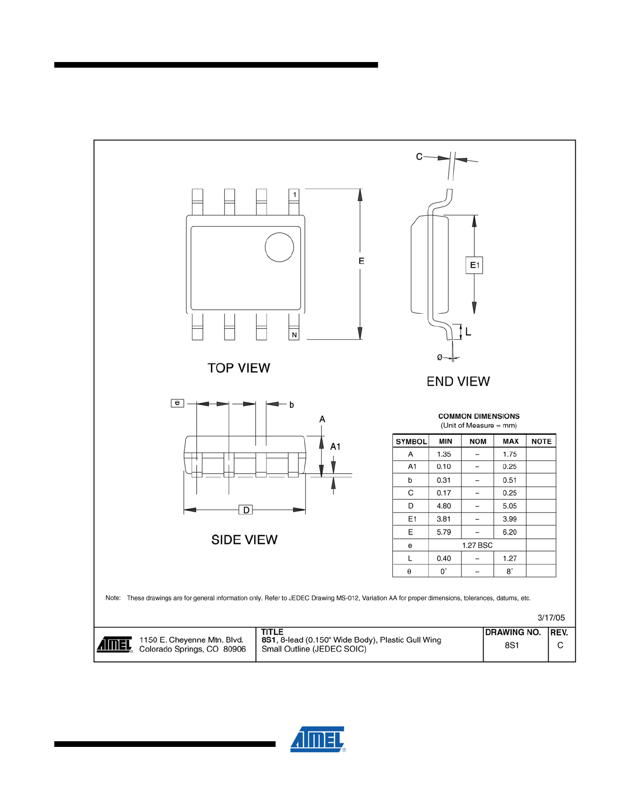
Table 6. Package Type
Package Type
Description
8S1
8-lead, 0.150” Wide, Plastic Gull Wing Small Outline Package (JEDEC SOIC)
CryptoCompanion
™ Chip
9
5277DS–CryptoCompanion–9/09
4. Package
Drawing
Figure 3. 8S1 – SOIC
10
CryptoCompanion
™ Chip
5277DS–CryptoCompanion–9/09
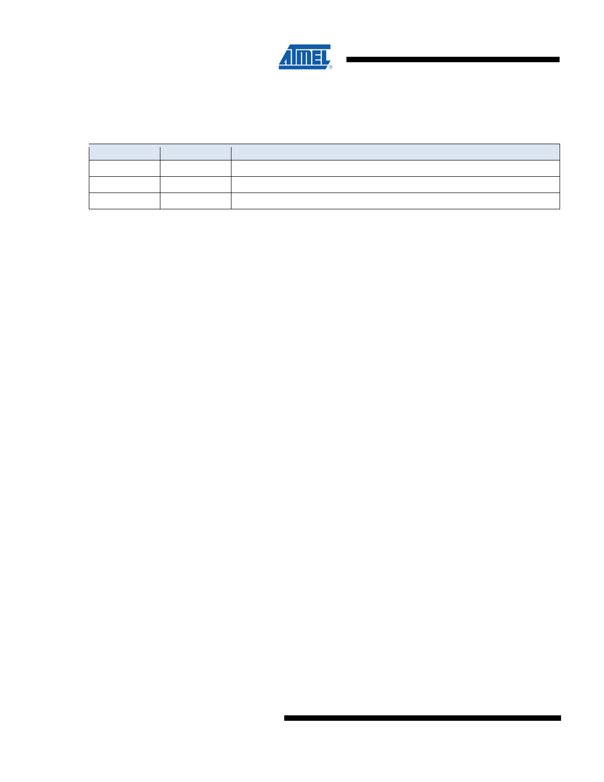
5. Revision
History
Doc. Rev.
Date
Comments
5277DS
09/2009
Finalized AC & DC Charateristics. Updated Counter information.
5277CS 02/2009
Document
updated.
5277BS
12/2008
Document updated.