
Copyright
©
Harris Corporation 1996
10-91
Harris Semiconductor
No. AN9334.1
October 1996
Harris Linear
Improving Start-up Time at 32kHz for the HA7210 Low Power
Crystal Oscillator
Author: Robert Rood
The HA7210 is a very low power crystal-controlled oscillator
that can be programmed to operate between 10kHz and
10MHz. In the lowest frequency range setting (FREQ 1 = 1,
FREQ 2 = 1), at 32kHz with a 5V supply and a 40pF load, the
HA7210 will draw a mere 10
µ
A. In this range (10kHz to
100kHz), the low power consumption may result in extended
oscillator start-up time. In higher frequency ranges, power
consumption gradually increases and start-up time is not an
issue. Several approaches to address low frequency start-up
time will be presented.
The first approach is to use the Enable/Disable Mode Pin.
This pin, when pulled low, will switch the output to a high
impedance state while an internal inverter continues to drive
the crystal in normal oscillation. This will result in a power
savings because very often a majority of the power dissipation
is used to drive the output load. In the disabled mode the
HA7210 will draw only 5
µ
A of standby current as compared to
10
µ
A above. This small amount of standby current gives the
benefit of instant start-up of a reliable and stable clock. The
Enable Time of the HA7210 is typically 800ns.
For applications where the voltage supply is removed from the
circuit or standby mode is not desired, the time from power
being applied until a stable square wave is generated can be
unexpectedly long. It should be noted that 32kHz crystal
parameters vary significantly from vendor to vendor and can
greatly affect the HA7210 (or any Pierce Oscillator) start-up
characteristic. Of particular importance is the Effective Series
Resistance (ESR) of the crystal, with lower ESR generally
providing faster start-up times (32kHz crystals with ESR
greater than 50k
Ω
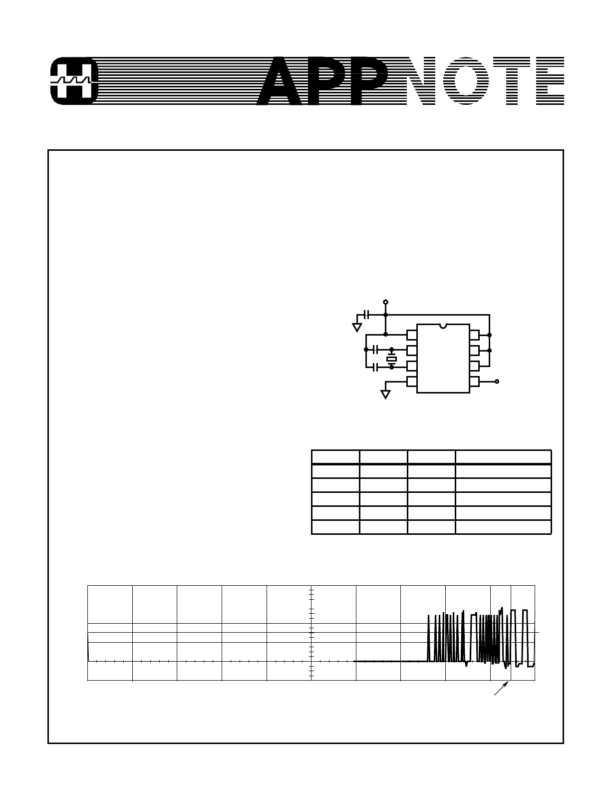
should be avoided). Using the circuit in Fig-
ure 1 the start-up characteristic of a 32.768kHz crystal, set in
the recommended lowest frequency range (FREQ 1 = 1,
FREQ 2 = 1) has a delay of 1.9s as shown in Figure 2.
FREQUENCY SELECTION TRUTH TABLE
ENABLE
FREQ 1
FREQ 2
OUTPUT RANGE
1
1
1
10kHz to 100kHz
1
1
0
100kHz to 1MHz
1
0
1
1MHz to 5MHz
1
0
0
5MHz to 10MHz
0
X
X
High-Z
V
DD
1
2
3
4
8
7
6
5
HA7210
32.768kHz
CLOCK
0.1
µ
F
ENABLE
FREQ 2
FREQ 1
10pF
10pF
32.768kHz
CRYSTAL
C
1
C
2
FIGURE 1. TYPICAL APPLICATION CIRCUIT
0.0s
1.0s
1.892s
2.0s
0V
V
DD
= 5V, C
1
= 10pF, C
2
= 10pF, FREQ 1 = 1, FREQ 2 = 1, CRYSTAL = EPSON (C-001R 32.768K-A)
2V/DIV.
200ms/DIV.
FIGURE 2. START-UP CHARACTERISTIC AT 32kHz WITH FREQ 1 = 1 AND FREQ 2 = 1
10-92
The start-up time can be improved by switching to the next
higher frequency range setting, where FREQ 1 = 1 and FREQ
2 = 0. In this setting the voltage that is internally applied to the
oscillating inverter increases from 1.4V to 2.2V providing more
power and higher transconductance. This increased power
comes at the expense of increased supply current. For a 32kHz
crystal, with V
DD
= 5V and a 40pF load the FREQ 1 = 1,
FREQ 2 = 0 setting will draw 30MA as compared to 10MA for
the FREQ 1 = 1, FREQ 2 = 1 range setting. Another concern
when using the next higher range is that the internal 15pF crys-
tal loading capacitors are disconnected. This means that the
user must provide external crystal loading capacitors for the
crystal to start properly in the higher range. The minimum val-
ues for C
1
and C
2
to provide reliable start-up was found to be
10pF each. The start-up time in the FREQ 1 = 1, FREQ 2 = 0
mode is shown in Figure 3 at 528ms, significantly faster than
the FREQ 1 = 1, FREQ 2 = 1 setting.
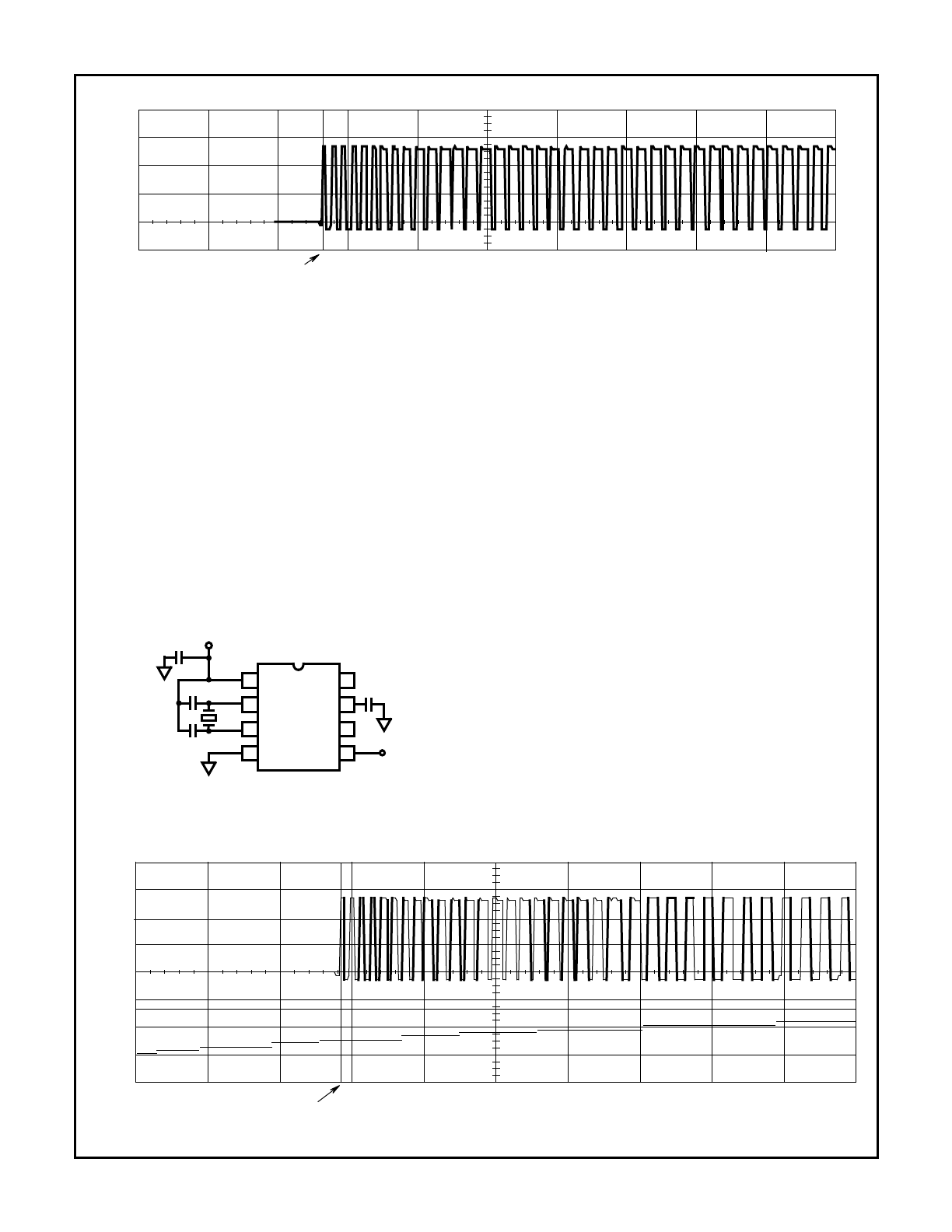
How can the benefits of faster start-up be gained without the
penalty of increased supply current? A solution to this prob-
lem is provided with the addition of a single capacitor C
F2
as
shown in Figure 4.
The digital inputs (ENABLE, FREQ 1, FREQ 2) provide internal
pull-up devices. These P-Channel devices provide 0.4
µ
A of
current to insure that an input will go to the “1” state if left open.
This pull-up current is used to charge a 0.22
µ
F capacitor (C
F2
)
connected to the FREQ 2 pin. At power-up C
F2
has zero
charge and holds FREQ 2 “low”, (FREQ 1 = 1, FREQ 2 = 0) so
that the HA7210 will give a fast start-up. Then the 0.4
µ
A pull-up
current will slowly charge C
F2
until it reaches a “high” state
(FREQ 1 = 1, FREQ 2 = 1) and the part draws lower supply cur-
rent. The FREQ 2 pin must be held low until the oscillation has
fully started to insure a start-up time improvement. The digital
input threshold is about 1.5V, providing a delay determined by:
The results are shown in Figure 5. Notice that CH 2 doesn’t
go all the way to 5V as expected. This is due to the 10M
Ω
scope probe loading the 0.4
µ
A current source. This probe
loading also causes CH 2 (FREQ 2 pin) to have an RC
shape rather that the expected linear trace.
In summary, start-up time is an important consideration in the
design and crystal selection for low frequency crystal oscilla-
tors. This Application Note describes several alternatives to
improve start-up time utilizing unique features of the HA7210
while taking advantage of its extremely low supply current.
528ms
1.0s
0.0s
2.0s
0V
V
DD
= 5V, C
1
= 10pF, C
2
= 10pF, FREQ 1 = 1, FREQ 2 = 0, CRYSTAL = EPSON (C-001R 32.768K-A)
2V/DIV.
200ms/DIV.
FIGURE 3. START-UP CHARACTERISTIC AT 32kHz WITH FREQ 1 = 1 AND FREQ 2 = 0
V
DD
1
2
3
4
8
7
6
5
HA7210
32.768kHz
CLOCK
0.1
µ
F
ENABLE
FREQ 2
FREQ 1
10pF
10pF
32.768kHz
CRYSTAL
OUTPUT
0.22
µ
F
C
1
C
2
C
F2
FIGURE 4. FAST START-UP AT 32kHz WITH NO SUPPLY
CURRENT PENALTY
i
C
dv
dt
-------
=
dt
0.22
µ
F
(
)
1.5V
(
)
0.4
µ
A
----------------------------------------------
=
0.825s
=
568ms
0.0s
1.0s
2.0s
0V
0V
CH1
CH2
2V/DIV
200ms/DIV
FIGURE 5. START-UP CHARACTERISTIC AT 32kHz WITH SPEED-UP CIRCUIT
Application Note 9334