

Copyright
©
Harris Corporation 1996
10-89
Harris Semiconductor
No. AN9317.1
November 1996
Harris Linear
The HA7210 low power oscillator is ideal for battery powered
circuits that require a precision clock. It operates well from a
single 3V to 5V supply, uses extremely low current, and
produces a clock output that is very stable over temperature
and supply voltage. In addition, it requires only an external
crystal and can operate from under 32kHz to over 10MHz.
This application note shows how the HA7210 can be used
with a quad CMOS op amp to make a control circuit that will
automatically switch a battery-powered digital system into
micropower "sleep mode" when not in use and trigger the
system on again when an external event (sound, pressure,
etc.) is detected. This function is extremely useful for
applications like remote metering, where a battery-powered
system may need to record occasional events yet remain in
a power down state most of the time.
This control circuit can be configured to turn on with an AC
or DC coupled event sensor and turn off using either a
preset time delay or an external digital system command.
When triggered into the power-up mode, it supplies a
precision system clock, a buffered analog ground reference
and a scaling signal amplifier for an A/D converter. In the
power-down mode, it draws less than 50
µ
A of standby
current.
Circuit Operation
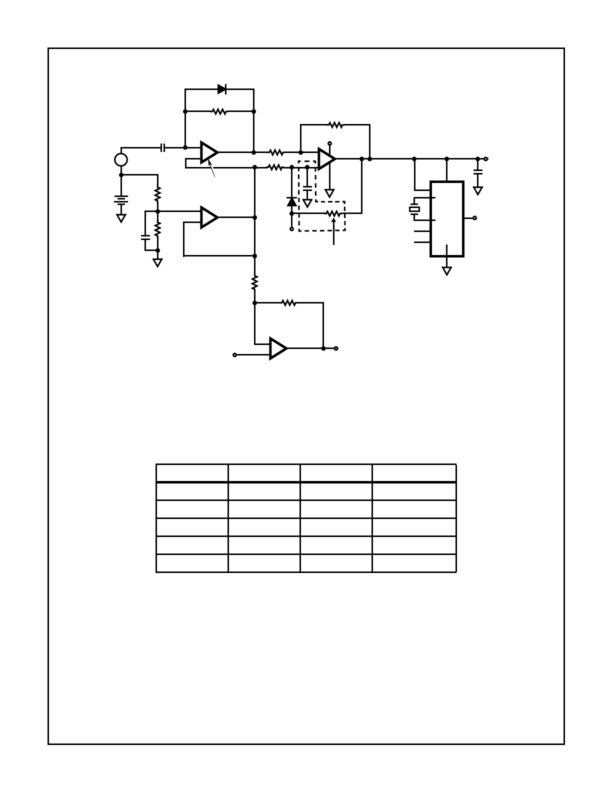
As shown in Figure 1, the control circuit operates from a sin-
gle 3V to 5V battery and uses only a quad CMOS op amp
(ICL7642) and a HA7210 low power oscillator chip. Two
Power-Down Reset options are available: one for a preset
time delay after turn-on, and another for external digital com-
mand as explained in the following text.
R
1
and R
2
create an analog signal ground reference voltage,
V
REF
, at 1/2 of the battery voltage. C
2
is used to filter noise
from this high impedance point. The analog reference volt-
age is then buffered by IC1A and output to the other three
amplifiers.
Amplifier B is used as a high-pass filter and amplifier such
that a fast edge (like a sudden noise into a microphone) will
produce a large positive swing at the output. Diode D
1
pre-
vents the output from moving very much below the analog
reference voltage. C
1
can be determined experimentally
depending on the application, sensor type, and sensitivity
required.
Amplifier C is used as a comparator and latch. The inverting
terminal is nominally at the analog reference, V
REF
, but the
non-inverting terminal is lower than V
REF
due to the
hysteresis of R
5
. In the absence of a microphone/sensor
signal, the output of amplifier B is also at V
REF
, so that
V
REF
(R
5
/(R
4
+ R
5
)) appears at the non-inverting input of
amplifier C.
When the output of amplifier B produces a voltage at the
non-inverting terminal of amplifier C higher than V
REF
, the
output of C latches into the high state. This state cannot be
changed by any condition at the input of IC1B due to the
hysteresis provided by R
5
. Because the output stage of
amplifier C is CMOS, it can drive a light load nearly to the
positive supply rail.
Voltage from the output of amplifier C is provided to the sup-
ply and ENable pins of the HA7210 low power oscillator.
When this happens, the oscillator turns on and provides a
clock output to the rest of the system. C
3
is used as a
bypass capacitor for the supply pin. If faster oscillator turn-on
is required, the HA7210 supply pin (pin 1) may be tied
directly to the battery and the output of amplifier C used to
enable the HA7210. In this case, the oscillator will draw
some quiescent current when not in use, but significantly
lower than when enabled. Capacitance at the output of the
HA7210 should be minimized to keep the active supply cur-
rent as low as possible.
As shown, amplifier D can be used as a scaling amplifier for
a system A/D converter. R
7
and R
8
are used to scale the
gain of the amplifier (G = 1 + R
8
/R
7
). The input of the ampli-
fier is extremely high impedance, so that any type of high
impedance sensor may be used.
Resetting the System
To put the system back into “sleep mode”, two options are
available. The digital system can send a logic high state to
the Reset input, forcing the IC1C comparator/latch to reset
to the low state. Alternatively, if desired, an auto-reset RC
timer (shown in the dotted lines) will cause the circuit to
automatically reset after a preset time interval. This time is
determined by the time it takes for the capacitor at the invert-
ing terminal to charge higher than the voltage at the non-
inverting terminal of IC1C.
Micropower Clock Oscillator and Op Amps Provide System
Control for Battery Operated Circuits (HA7210)
Author: Al Little and James Ho
10-90
Application Note 9317
MICROPHONE/
SENSOR
ICL7642
HA7210
EN
EXTERNAL
CRYSTAL
FREQ 1
FREQ 2
SYSTEM CLOCK OUT
(SEE CHART)
V
BATTERY
V
BATTERY
3V-5V
1/4
ICL7642
1/4
ICL7642
1/4
RESET
AUTO RESET
AMPLIFIED ANALOG SIGNAL TO A/D
ANALOG SIGNAL INPUT
ICL7642
1/4
10nF
10nF
SYSTEM ENABLE
IC1A
IC1B
IC1C
IC1D
IC2
1
2
3
7
6
5
8
9
10
14
13
12
1
V
DD
8
2
3
6
4
5
7
R
1
1M
R
2
1M
C
2
C
1
10nF
R
3
1M
R
4
1M
R
6
1M
D
1
D
2
R
5
3M
R
7
R
8
1N914
1N914
4
11
C
3
V
REF
+
-
+
-
+
-
NOTE: Provides Sleep Mode, Power-up Trigger, Optional Auto-reset, Scaling Amp for A/D, Precision System Clock Oscillator, and Analog
Ground Reference
FIGURE 1. 2-CHIP MICROPOWER CONTROL CIRCUIT OPERATES FROM 3V BATTERY
+
-
TABLE 1. HA7210 OSCILLATOR CONTROL INPUTS
ENABLE
FREQ 1
FREQ 2
OUTPUT RANGE
1
1
1
10kHz to 100kHz
1
1
0
100kHz to 1MHz
1
0
1
1MHz to 5MHz
1
0
0
5MHz to 10MHz+
0
X
X
High Impedance